
Related Manuals for Miller Syncrowave 180 SD


Summary of Contents for Miller Syncrowave 180 SD
- Page 1 OM-355 188 290A March 2000 Processes TIG (GTAW) Welding Stick (SMAW) Welding Description Arc Welding Power Source Syncrowave 180 SD Visit our website at www.MillerWelds.com...
- Page 2 – every power source from This Owner’s Manual is designed to help you get the most out of your Miller is backed by the most Miller products. Please take time to read the Safety precautions. They will hassle-free warranty in the business.
-
Page 3: Table Of Contents
TABLE OF CONTENTS SECTION 1 – SAFETY PRECAUTIONS - READ BEFORE USING ......1-1. -
Page 5: Section 1 - Safety Precautions - Read Before Using
SECTION 1 – SAFETY PRECAUTIONS - READ BEFORE USING som _nd_5/97 1-1. Symbol Usage Means Warning! Watch Out! There are possible hazards with this procedure! The possible hazards are shown in the adjoining symbols. This group of symbols means Warning! Watch Out! possible Y Marks a special safety message. - Page 6 ARC RAYS can burn eyes and skin. BUILDUP OF GAS can injure or kill. D Shut off shielding gas supply when not in use. Arc rays from the welding process produce intense D Always ventilate confined spaces or use visible and invisible (ultraviolet and infrared) rays that can burn eyes and skin.
-
Page 7: Additional Symbols For Installation, Operation, And Maintenance
1-3. Additional Symbols For Installation, Operation, And Maintenance FIRE OR EXPLOSION hazard. MOVING PARTS can cause injury. D Do not install or place unit on, over, or near D Keep away from moving parts such as fans. combustible surfaces. D Keep all doors, panels, covers, and guards D Do not install unit near flammables. -
Page 8: Emf Information
1-5. EMF Information Considerations About Welding And The Effects Of Low Frequency 1. Keep cables close together by twisting or taping them. Electric And Magnetic Fields 2. Arrange cables to one side and away from the operator. Welding current, as it flows through welding cables, will cause electro- magnetic fields. -
Page 9: Section 1 - Consignes De Securite - Lire Avant Utilisation
SECTION 1 – CONSIGNES DE SECURITE – LIRE AVANT UTILISATION som _nd_fre 5/97 1-1. Signification des symboles Signifie Mise en garde ! Soyez vigilant ! Cette procédure présente des risques de danger ! Ceux-ci sont identifiés par des symboles adjacents aux directives. Ce groupe de symboles signifie Mise en garde ! Soyez vigilant ! Il y a des Y Identifie un message de sécurité... - Page 10 LES RAYONS DE L’ARC peuvent pro- LES ACCUMULATIONS DE GAZ ris- voquer des brûlures dans les yeux et quent de provoquer des blessures ou sur la peau. même la mort. Le rayonnement de l’arc du procédé de soudage D Fermer l’alimentation du gaz protecteur en cas de génère des rayons visibles et invisibles intenses non utilisation.
-
Page 11: Dangers Supplémentaires En Relation Avec L'installation, Le Fonctionnement Et La Maintenance
1-3. Dangers supplémentaires en relation avec l’installation, le fonctionnement et la maintenance Risque D’INCENDIE OU DES ORGANES MOBILES peuvent D’EXPLOSION. provoquer des blessures. D Ne pas placer l’appareil sur, au-dessus ou à proxi- D Rester à l’écart des organes mobiles comme le mité... -
Page 12: Principales Normes De Sécurité
1-4. Principales normes de sécurité Safety in Welding and Cutting, norme ANSI Z49.1, de l’American Wel- Safe Handling of Compressed Gases in Cylinders, CGA Pamphlet P-1, ding Society, 550 N.W. Lejeune Rd, Miami FL 33126 de la Compressed Gas Association, 1235 Jefferson Davis Highway, Suite 501, Arlington, VA 22202. -
Page 13: Section 2 - Installation
SECTION 2 – INSTALLATION 2-1. Included with Your Unit 12 ft (3.7 m) Work Cable With Clamp And Quick-Connect 150 Amp TIG Torch with 12-1/2 ft (3.8 m) Cable Electrode Holder and Quick-Connect Gas Hose Gas Regulator RFCS-14 Foot Control with 20 ft (6 m) Cable 8 ft (2.4 m) Primary Cord Some assembly is required. -
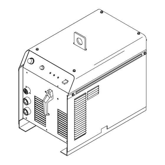
Page 14: Dimensions And Weights
2-3. Dimensions And Weights Dimensions Height 21 in (533 mm) Width 13-5/8 in (346 mm) Length 22-1/8 in (562 mm) 21-5/16 in (541 mm) 13/16 in (21 mm) 12-7/16 in (316 mm) 1–1/16 in (27 mm) 4 Holes 1/2 (13 mm) Weight Front 210 lbs (95 kg) -
Page 15: Volt-Ampere Curves
2-6. Volt-Ampere Curves Volt-ampere curves show minimum and maximum voltage and amper- age output capabilities of welding power source. Curves of other set- tings fall between curves shown. DC MODE AC MODE STICK–MAX TIG–MAX Stick MIN Stick MAX TIG–MIN STICK–MIN AMPERES AMPERES ssb1.1 10/91 –... -
Page 16: Remote 14 Receptacle
2-8. Remote 14 Receptacle NOTE Remote control device has complete control of amperage at all times when connected to Remote 14 receptacle. Socket* Socket Information 24 volts DC. Contact closure to A completes 24 volts DC contactor control circuit. Command reference; 0 to +10 volts DC output to remote control. Remote control circuit common. -
Page 17: Electrical Service Guide
2-10. Electrical Service Guide NOTE All values calculated at 40% duty cycle. Input Voltage Input Amperes at Rated Output Max Recommended Standard Fuse Or Circuit Breaker Rating In Amperes Min Input Conductor Size In AWG/Kcmil Max Recommended Input Conductor Length In Feet (Meters) 166 (51) Min Grounding Conductor Size In AWG/Kcmil Reference: 1996 National Electrical Code (NEC) -
Page 18: Section 3 - Operation
SECTION 3 – OPERATION 3-1. Controls Ref. ST-188 714-A Output Selector Switch For remote amperage control used when TIG lize welding arc. For AC welding, the arc starter Y Do not use AC output in damp areas, if (GTAW) welding, front panel Amperage control will turn on and stay on to start and stabilize the setting is the maximum amperage available at welding arc. -
Page 19: Example Of Front Panel Amperage Control
3-2. Example of Front Panel Amperage Control For Stick (SMAW) Welding Select weld process. Select polarity. Select amperage. In Example: Remote weld amperage = 10–180 amps DC NOTE: Remote amperage control is active whenever a remote control is connected. If the remote device does not include a means of controlling amperage through pin E, the Amperage Adjustment control on the front panel remains active. -
Page 20: Typical Tig Connections
3-4. Typical TIG Connections Remote Foot Control A customer supplied remote finger- tip control may also be used. Torch Work Clamp Connect remote control, torch, and work clamp to receptacles as shown. Cylinder Chain or secure cylinder to running gear, wall, or other stationary support. -
Page 21: Process And Material Thickness Guide Label
3-6. Process and Material Thickness Guide Label Guideline For Welding Process And Output For Material Material Thickness Material And 22 ga 20 ga 18 ga 16 ga 14 ga 12 ga 11 ga 10 ga 6 ga 2 ga – 0.033 in 0.036 in 0.048 in... -
Page 22: Adjusting Spark Gaps
4-2. Adjusting Spark Gaps Y Turn Off power before ad- Tools Needed: justing spark gaps. Remove left side panel. Tungsten End Of Point Replace point if tungsten end dis- appears; do not clean or dress tungsten. Spark Gap Normal spark gap is 0.012 in (0.305 mm). -
Page 23: Section 6 - Electrical Diagram
SECTION 5 – ELECTRICAL DIAGRAM SD-188 274-D Figure 5-1. Circuit Diagram For Welding Power Source OM-355 Page 19... -
Page 24: Section 7 - High Frequency (Hf)
SECTION 6 – HIGH FREQUENCY (HF) 6-1. Welding Processes Using HF HF Voltage GTAW – helps arc jump air gap between torch and workpiece and/ or stabilize the arc. SAW – helps arc reach workpiece through flux granules. Flux Work Work Gas Tungsten Arc Submerged Arc... -
Page 25: Correct Installation
6-3. Correct Installation Weld Zone 50 ft (15 m) 50 ft (15 m) Ground All Metal Objects And All Wiring In Welding Zone Using #12 AWG Ground Wire Workpiece If Required By Codes Nonmetal Building Metal Building Ref. S-0695 / Ref. S-0695 HF Source (Welder With Built-In HF Or Electrically join (bond) all conduit sections Metal Building Panel Bonding Methods... -
Page 26: Section 7 - Selecting And Preparing Tungsten Electrode
SECTION 7 – SELECTING AND PREPARING TUNGSTEN ELECTRODE gtaw2 7/97 NOTE For additional information, see your distributor for a handbook on the Gas Tungsten Arc Welding (GTAW) process. Wear clean gloves to prevent contamination of tungsten electrode. 7-1. Selecting Tungsten Electrode ♦... -
Page 27: Preparing Tungsten For Dc Electrode Negative (Dcen) Welding
7-3. Preparing Tungsten For DC Electrode Negative (DCEN) Welding Tungsten Electrode Tapered End Grind end of tungsten on fine grit, hard abrasive wheel before weld- ing. Do not use wheel for other jobs or tungsten can become contami- nated causing lower weld quality. 2-1/2 Times Electrode Diameter Stable Arc... -
Page 28: Section 8 - Guidelines For Tig Welding (Gtaw)
SECTION 8 – GUIDELINES FOR TIG WELDING (GTAW) 8-1. Positioning The Torch Y Grinding the tungsten elec- trode produces dust and fly- ing sparks which can cause injury and start fires. Use lo- cal exhaust (forced ventila- tion) at the grinder or wear an approved respirator. -
Page 29: Torch Movement During Welding
8-2. Torch Movement During Welding Tungsten Without Filler Rod ° Welding direction Form pool Tilt torch Move torch to front of pool. Repeat process. Tungsten With Filler Rod ° ° Welding direction Form pool Tilt torch Add filler metal Remove rod Move torch to front of pool. -
Page 30: Positioning Torch Tungsten For Various Weld Joints
8-3. Positioning Torch Tungsten For Various Weld Joints ° Butt Weld And Stringer Bead ° ° ° “T” Joint ° ° ° ° Lap Joint ° ° ° ° Corner Joint ° ° ST-162 003 / S-0792 OM-355 Page 26... - Page 31 Notes OM-355 Page 27...
-
Page 32: Section 9 - Stick Welding (Smaw) Guidelines
SECTION 9 – STICK WELDING (SMAW) GUIDELINES 9-1. Stick Welding Procedure Y Weld current starts when electrode touches work- piece. Y Weld current can damage electronic parts in vehicles. Disconnect both battery cables before welding on a vehicle. Place work clamp as close to the weld as possible. - Page 33 9-2. Electrode and Amperage Selection Chart 3/32 6010 5/32 & 3/16 6011 7/32 6010 DEEP MIN. PREP, ROUGH 1/16 HIGH SPATTER 6011 DEEP 5/64 6013 EP,EN GENERAL 3/32 SMOOTH, EASY, 6013 7014 EP,EN FAST 5/32 3/16 LOW HYDROGEN, 7018 STRONG 7/32 FLAT SMOOTH, EASY,...
- Page 34 9-5. Positioning Electrode Holder ° ° ° ° End View of Work Angle Side View of Electrode Angle GROOVE WELDS ° ° ° ° End View of Work Angle Side View of Electrode Angle FILLET WELDS S-0060 9-6. Poor Weld Bead Characteristics Large Spatter Deposits Rough, Uneven Bead Slight Crater During Welding...
- Page 35 9-8. Conditions That Affect Weld Bead Shape NOTE Weld bead shape is affected by electrode angle, arc length, travel speed, and thickness of base metal. Correct Angle ° - ° Angle Too Large Angle Too Small Drag ELECTRODE ANGLE Spatter Normal Too Long Too Short...
- Page 36 9-10. Butt Joints Tack Welds Prevent edges of joint from drawing together ahead of electrode by tack welding the materials in position be- fore final weld. Square Groove Weld Good for materials up to 3/16 in (5 mm) thick. Single V-Groove Weld °...
- Page 37 9-13. Weld Test Vise Weld Joint Hammer Strike weld joint in direction shown. A good weld bends over but does not break. 2 To 3 in (51-76 mm) 2 To 3 in (51-76 mm) 1/4 in (6.4 mm) S-0057-B 9-14. Troubleshooting – Porosity Porosity –...
- Page 38 9-16. Troubleshooting – Incomplete Fusion Incomplete Fusion – failure of weld metal to fuse completely with base metal or a preceeding weld bead. Possible Causes Corrective Actions Insufficient heat input. Increase amperage. Select larger electrode and increase amperage. Improper welding technique. Place stringer bead in proper location(s) at joint during welding.
- Page 39 9-19. Troubleshooting – Burn-Through Burn-Through – weld metal melting completely through base metal resulting in holes where no metal remains. Possible Causes Corrective Actions Excessive heat input. Select lower amperage. Use smaller electrode. Increase and/or maintain steady travel speed. 9-20. Troubleshooting – Waviness Of Bead Waviness Of Bead –...
-
Page 40: Section 10 - Parts List
SECTION 10 – PARTS LIST Hardware is common and ST-802 252-C Figure 10-1. Main Assembly not available unless listed. OM-355 Page 36... - Page 41 Item Dia. Part Description Quantity Mkgs. Figure 10-1. Main Assembly ....188 270 COVER, top ........... . .
- Page 42 Hardware is common and not available unless listed. ST-802 254 Figure 10-2. Panel, Front w/Components Item Dia. Part Description Quantity Mkgs. Figure 10-2. Panel, Front w/Components (Figure 10-1 Item 39) ....174 991 KNOB, pointer .
- Page 43 Effective January 1, 2000 (Equipment with a serial number preface of “LA” or newer) This limited warranty supersedes all previous Miller warranties and is exclusive with no other Warranty Questions? guarantees or warranties expressed or implied. Call LIMITED WARRANTY – Subject to the terms and conditions APT, ZIPCUT &...
-
Page 44: Options And Accessories
Distributor Address City State For Service Call 1-800-4-A-Miller or see our website at www.MillerWelds.com to locate a DISTRIBUTOR or SERVICE AGENCY near you. Always provide Model Name and Serial/Style Number. Contact your Distributor for: Welding Supplies and Consumables Options and Accessories...
Need help?
Do you have a question about the Syncrowave 180 SD and is the answer not in the manual?
Questions and answers