Table of Contents
Troubleshooting

Related Manuals for Miller RAD-400


Summary of Contents for Miller RAD-400
- Page 1 OM-1598 199 752M 2011−08 Processes Submerged (SAW) Welding Description Heavy Duty Wire Feeder For Automated Welding Applications RAD-400, RAD-400T and RAD-780 Motor/Drive Assemblies Visit our website at www.MillerWelds.com...
- Page 2 We know you don’t have time to do it any other way. That’s why when Niels Miller first started building arc welders in 1929, he made sure his products offered long-lasting value and superior quality.
-
Page 3: Table Of Contents
TABLE OF CONTENTS SECTION 1 − SAFETY PRECAUTIONS - READ BEFORE USING ....... . . 1-1. - Page 4 DECLARATION OF CONFORMITY for European Community (CE marked) products. MILLER Electric Mfg. Co., 1635 Spencer Street, Appleton, WI 54914 U.S.A. declares that the product(s) identified in this declaration conform to the essential requirements and provisions of the stated Council Directive(s) and Standard(s).
-
Page 5: Section 1 − Safety Precautions - Read Before Using
SECTION 1 − SAFETY PRECAUTIONS - READ BEFORE USING som 2011−01 Protect yourself and others from injury — read and follow these precautions. 1-1. Symbol Usage DANGER! − Indicates a hazardous situation which, if Indicates special instructions. not avoided, will result in death or serious injury. The possible hazards are shown in the adjoining symbols or explained in the text. - Page 6 D Remove stick electrode from holder or cut off welding wire at FUMES AND GASES can be hazardous. contact tip when not in use. D Wear oil-free protective garments such as leather gloves, heavy Welding produces fumes and gases. Breathing shirt, cuffless trousers, high shoes, and a cap.
-
Page 7: Additional Symbols For Installation, Operation, And Maintenance
1-3. Additional Symbols For Installation, Operation, And Maintenance FIRE OR EXPLOSION hazard. MOVING PARTS can injure. D Do not install or place unit on, over, or near D Keep away from moving parts such as fans. combustible surfaces. D Keep all doors, panels, covers, and guards D Do not install unit near flammables. -
Page 8: California Proposition 65 Warnings
1-4. California Proposition 65 Warnings For Gasoline Engines: Welding or cutting equipment produces fumes or gases which contain chemicals known to the State of California to Engine exhaust contains chemicals known to the State of cause birth defects and, in some cases, cancer. (California California to cause cancer, birth defects, or other reproduc- Health &... -
Page 9: Section 2 − Consignes De Sécurité − Lire Avant Utilisation
SECTION 2 − CONSIGNES DE SÉCURITÉ − LIRE AVANT UTILISATION fre_som_2010−03 Se protéger et protéger les autres contre le risque de blessure — lire et respecter ces consignes. 2-1. Symboles utilisés DANGER! − Indique une situation dangereuse qui si on Indique des instructions spécifiques. - Page 10 Il reste une TENSION DC NON NÉGLIGEABLE dans LE SOUDAGE peut provoquer un les sources de soudage onduleur UNE FOIS incendie ou une explosion. l’alimentation coupée. Le soudage effectué sur des conteneurs fermés tels D Arrêter les convertisseurs, débrancher le courant électrique et que des réservoirs, tambours ou des conduites peut décharger les condensateurs d’alimentation selon les instructions provoquer leur éclatement.
-
Page 11: Dangers Supplémentaires En Relation Avec L'installation, Le Fonctionnement Et La Maintenance
ACCUMULATIONS LES BOUTEILLES peuvent exploser risquent de provoquer des blessures si elles sont endommagées. ou même la mort. Les bouteilles de gaz comprimé contiennent du gaz D Fermer l’alimentation du gaz comprimé en cas sous haute pression. Si une bouteille est endommagée, elle peut exploser. -
Page 12: Proposition Californienne 65 Avertissements
Les PIÈCES MOBILES peuvent RAYONNEMENT HAUTE causer des blessures. FRÉQUENCE (H.F.) risque provoquer des interférences. D Ne pas s’approcher des organes mobiles. D Ne pas s’approcher des points de coincement D Le rayonnement haute fréquence (H.F.) peut tels que des rouleaux de commande. provoquer des interférences avec les équi- pements de radio−navigation et de com- munication, les services de sécurité... -
Page 13: Principales Normes De Sécurité
2-5. Principales normes de sécurité Safety in Welding, Cutting, and Allied Processes, ANSI Standard Z49.1, 25 West 43rd Street, New York, NY 10036 (téléphone : 212-642-4900, de Global Engineering Documents (téléphone : 1-877-413-5184, site site Internet : www.ansi.org). Internet : www.global.ihs.com). Standard for Fire Prevention During Welding, Cutting, and Other Hot Safe Practices for the Preparation of Containers and Piping for Welding Work, NFPA Standard 51B, de National Fire Protection Association,... - Page 14 OM-1598 Page 10...
-
Page 15: Section 3 − Definitions
SECTION 3 − DEFINITIONS 3-1. Warning Label Electric Shock and Pinch Points Warning! Watch Out! There are possible hazards as shown by the symbols. Drive rolls can injure fingers Welding wire and drive parts are at welding voltage during operation − keep hands and metal objects away. -
Page 16: Section 4 − Installation
SECTION 4 − INSTALLATION 4-1. Important Information Regarding CE Products (Sold Within The EU) A. Information On Electromagnetic Fields (EMF) This equipment shall not be used by the general public as the EMF limits for the general public might be exceeded during welding. This equipment is built in accordance with EN 60974−1 and is intended to be used only in an occupational environment (where the general public access is prohibited or regulated in such a way as to be similar to occupational use) by an expert or an instructed person. -
Page 17: Description
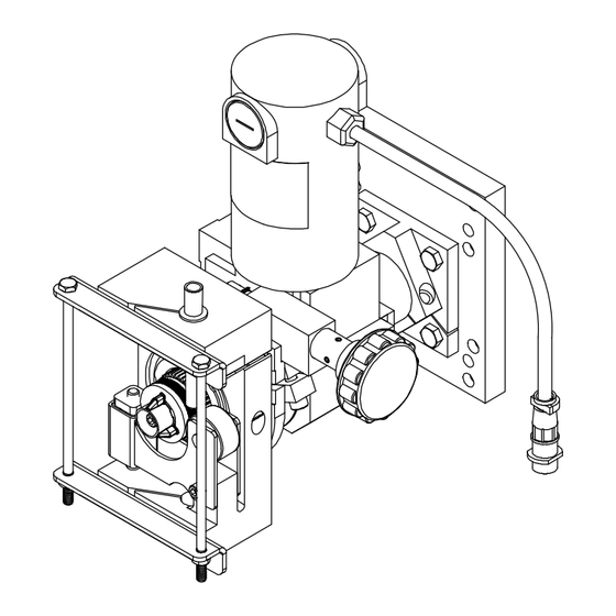
4-4. Description Motor/drive Assembly This unit is a heavy-duty wire feed- ing motor/drive assembly designed for automated Submerged Arc Welding (SAW) applications. The various model designations in- dicate information about the specif- ic model. The units are offered in ei- ther low speed or standard speed drives. -
Page 18: Typical Equipment Location
4-6. Typical Equipment Location Side View Front View 804 907-A Welding Power Source Weld Control Wire Drive Assembly Side Beam Spool Support Sub-Arc Welding Torch Flux Hopper Notes OM-1598 Page 14... -
Page 19: Installing Wire Guide And Drive Roll
4-7. Installing Wire Guide And Drive Roll When changing wire size or type, check drive roll size (see Table 5-1). Wire Pressure Adjustment Screw (Hidden) Loosen screw to decrease tension on spring. Drive Roll Nut Drive Roll Remove drive roll. Drive Roll Carrier Turn nut one click to line up lobes with lobes on drive roll carrier. -
Page 20: Plug Connections
4-8. Plug Connections Weld Control Motor Control Cord (Not Supplied) Motor/Drive Assembly To make connections, align key- way, insert plug, and tighten threaded collar. RAD motor shown without feed roller guard. 804 966-A OM-1598 Page 16... -
Page 21: Threading And Feeding Welding Wire
4-9. Threading And Feeding Welding Wire Hold wire tightly to keep it from unraveling. POWER Tools Needed: Weld Control Welding Power Source 6 in. (150 mm) Pull and hold wire; cut off end. Set switches. WIRE ADVANCE RAD motor shown without feed roller guard. -
Page 22: Manually Changing Feed Plate Angle
4-11. Manually Changing Feed Plate Angle Adjusting Knob Turn adjusting knob to change torch angle. Hub Clamp Screw Tighten screw. Feed Plate Screw Loosen screw. The feed plate maximum tilt angle is about 15 degrees from center in both directions. RAD motor shown without feed roller Tools Needed:... -
Page 23: Location Of Torch For Tandem Arc Applications
4-12. Location Of Torch For Tandem Arc Applications Follow instructions below to change torch to right of center or left of center. Assembly As Shipped (With torch right of center) Tools Needed: 1/4, 3/16 in. RAD motor shown Torch Right Of Center Torch Left Of Center (With tilt angle adjusting knob on left side) without feed roller... -
Page 24: Section 5 − Maintenance And Troubleshooting
SECTION 5 − MAINTENANCE AND TROUBLESHOOTING 5-1. Routine Maintenance Disconnect power before maintaining. 3 Months Clean Repair Or Replace Replace Unreadable Tighten Cracked Labels Weld Weld Terminals Cable Replace Cord Cracked Hose Cable Parts 6 Months Blow Out Or Clean Vacuum Inside. -
Page 25: Brush Inspection And Replacement
5-2. Brush Inspection And Replacement Brush Cap Spring Clip Brush 3/8 in. (9.5 mm) Minimum Length Remove brush cap. Remove spring clip and brush. 3/4 in. (19 mm) Replace brush if it becomes chipped New Length or broken, or if less than 3/8 in. (9.5 mm) of brush material is left. -
Page 26: Section 6 − Electrical Diagram
SECTION 6 − ELECTRICAL DIAGRAM PLG1 GREEN Motor BROWN PLG1 BARE GREEN BLACK TACH WHITE Figure 6-1. Circuit Diagram OM-1598 Page 22... - Page 27 Notes OM-1598 Page 23...
-
Page 28: Section 7 − Parts List
SECTION 7 − PARTS LIST Hardware is common and not available unless listed. 10 11 See Figure 7-2 For Replacement Drive Rolls Ref. 198 480-K Figure 7-1. Wire Drive Assembly Item Dia. Part Mkgs. Description Quantity 195 265 Figure 7-1. Wire Drive Assembly 195 266 300 250 . - Page 29 Item Dia. Part Mkgs. Description Quantity 195 265 Figure 7-1. Wire Drive Assembly (Continued) 195 266 300 250 ... . 209 498 ..Assembly, Mounting Motor .
- Page 30 Notes...
- Page 31 Effective January 1, 2011 (Equipment with a serial number preface of MB or newer) This limited warranty supersedes all previous Miller warranties and is exclusive with no other Warranty Questions? guarantees or warranties expressed or implied. LIMITED WARRANTY − Subject to the terms and conditions 90 Days —...
- Page 32 Contact the Delivering Carrier to: File a claim for loss or damage during shipment. For assistance in filing or settling claims, contact your distributor and/or equipment manufacturer’s Transportation Department. © ORIGINAL INSTRUCTIONS − PRINTED IN USA 2011 Miller Electric Mfg. Co. 2011−01...
Need help?
Do you have a question about the RAD-400 and is the answer not in the manual?
Questions and answers