
Related Manuals for Miller RFCS-5


Summary of Contents for Miller RFCS-5
- Page 1 OM-844 183973P 2020-06 Foot Controls RFCS-5, RFCS-5HD, RFCS-6M, RFCS-14, And RFCS-14HD OWNER’S MANUAL For product information, Owner’s Manual translations, and more, visit www.MillerWelds.com...
- Page 2 We know you don’t have time to do it any other way. That’s why when Niels Miller first started building arc welders in 1929, he made sure his products offered long-lasting value and superior quality.
-
Page 3: Table Of Contents
TABLE OF CONTENTS SECTION 1 − INSTALLATION AND OPERATION ..........1-1. -
Page 5: Section 1 − Installation And Operation
1-3. Information About Default Weld Parameters And Settings NOTICE − Each welding application is unique. Although certain Miller Electric products are designed to determine and default to certain typical welding parameters and settings based upon specific and relatively limited application variables input by the end user, such default settings are for reference purposes only;... -
Page 6: Typical Connection
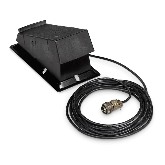
1-4. Typical Connection Turn Off welding power source before connecting foot control. 1. Foot Control 2. Remote 14, Remote 5, Or Remote 6 Receptacle Insert plug into matching 14-sock- et, 5-socket, or 6-socket recep- tacle, as applicable, on welding power source. Tighten collar. Ref. -
Page 7: Remote Amperage Control For Welding Power Source With Remote Control Switch
1-6. Remote Amperage Control For Welding Power Source With Remote Control Switch But Without Output (Contactor) Control Example Of Combination Front Panel And Remote Amperage Control See welding power source Owner’s Manual to determine if Remote Foot Control works as a combination or as full Am- perage control. -
Page 8: Remote Amperage Control For Welding Power Source With Remote Control Switch
1-7. Remote Amperage Control For Welding Power Source With Remote Control Switch And Output (Contactor) Control Example Of Combination Front Panel And Remote Amperage Control See welding power source Owner’s Manual to determine if Remote Foot Control works as a combination or as full Am- perage control. -
Page 9: Adjusting Potentiometer Timing
1-8. Adjusting Potentiometer Timing NOTICE − Disconnect foot control from welding power source/gener- ator before adjusting potentiome- ter. Turn unit upside down, and remove bottom plate. 1. Label 2. Gear Turn gear on potentiometer shaft BEFORE RE-INSTALLING BELT, TURN GEAR ALL counterclockwise as far as THE WAY TO THE STOP. -
Page 10: Section 2 − Electrical Diagrams
SECTION 2 − ELECTRICAL DIAGRAMS Circuit Diagram For RFCS-5, RFCS-5HD, RFCS-14, And RFCS-14HD Models 183957-B Circuit Diagram For RFCS-6M Models 208615-B OM-844 Page 6... -
Page 11: Section 3 − Parts List
SECTION 3 − PARTS LIST 801735-B Quantity RFCS Models Item Dia. Part 14HD Mkgs. Description ....182030 Belt ....... . . - Page 12 Notes...
- Page 13 Notes MATERIAL THICKNESS REFERENCE CHART 24 Gauge (.025 in) 22 Gauge (.031 in) 20 Gauge (.037 in) 18 Gauge (.050 in) 16 Gauge (.063 in) 14 Gauge (.078 in) 1/8 in (.125 in) 3/16 in (.188 in) 1/4 in (.25 in) 5/16 in (.313 in) 3/8 in (.375 in) 1/2 in (.5 in)
- Page 14 Notes Work like a Pro! Pros weld and cut safely. Read the safety rules at the beginning of this manual.
- Page 15 Effective January 1, 2020 (Equipment with a serial number preface of NA or newer) This limited warranty supersedes all previous Miller warranties and is exclusive with no other guarantees or warranties expressed or implied. LIMITED WARRANTY − Subject to the terms and conditions...
- Page 16 Contact the Delivering Carrier to: File a claim for loss or damage during shipment. For assistance in filing or settling claims, contact your distributor and/or equipment manufacturer’s Transportation Department. © ORIGINAL INSTRUCTIONS − PRINTED IN USA 2020 Miller Electric Mfg. LLC 2020−01...
Need help?
Do you have a question about the RFCS-5 and is the answer not in the manual?
Questions and answers