Advertisement
Quick Links
Advertisement

Related Manuals for Chef CS910CS


Summary of Contents for Chef CS910CS
- Page 1 RANGEHOOD User Manual CS910CS, CRC914SB, CRC914DB...
- Page 2 CONGRATULATIONS CONTENTS Congratulations and thank you for choosing our canopy Important safety instructions ... . . rangehood. We are sure you will find your new rangehood Description of your rangehood ... . a pleasure to use.
- Page 3 IMPORTANT SAFETY INSTRUCTIONS IMPORTANT SAFETY INSTRUCTIONS This manual explains the proper use of your new canopy Always cover lit gas burners with pots or pans when rangehood. Please read this manual carefully before using canopy rangehood is in use. the product. This manual should be kept in a safe place for Always switch off gas burners before you remove pots This manual explains the proper use of your new Always cover lit gas burners with pots or pans when...
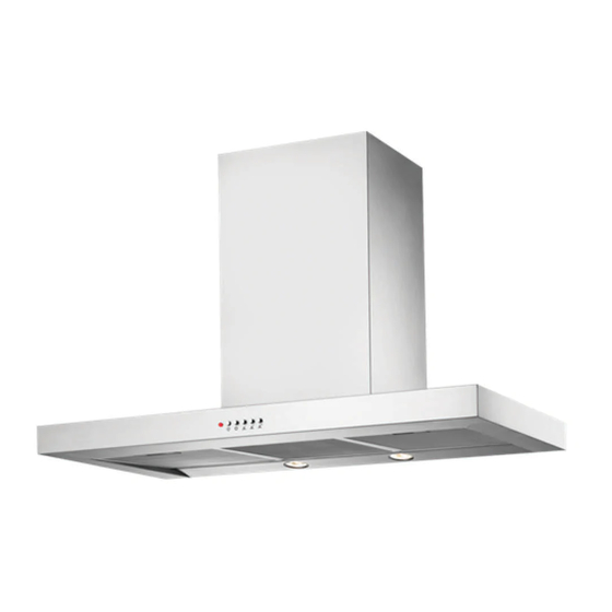
- Page 4 DESCRIPTION OF YOUR RANGEHOOD Flue pipe to be sourced locally Fig. 3 Components list Technical specifications 1. Screws x 2 MODEL CS910CS CRC914SB/CRC914DB 2. Telescopic flue cover set Height 69-113.5cm 69-113.5cm 3. Upper flue cover mounting bracket 4. Lower flue cover mounting bracket...
- Page 5 RANGEHOOD DIMENSIONS 290mm 320mm 538mm 1135mm (maximum) 690mm (minimum) 56mm 900mm 500mm Fig. 4 NOTE: The fan housing flue transition duct is 150mm in diameter. (See page 11 for optional ducting accessories). 150mm Fig. 5...
- Page 6 INSTALLATION INSTALLATION PRE-INSTALLATION PRE-INSTALLATION INSTALLATION INSTALLATION Before installing the cooker hood, peel off any protective Before installing the cooker hood, peel off any protective 1. Using a spirit level mark a vertical centre line on the 1. Using a spirit level mark a vertical centre line on the plastic covering and remove polystyrene from inside behind plastic covering and remove polystyrene from inside behind wall where the hood is to be positioned, and a...
- Page 7 INSTALLATION Depending on the preferred installation/ducting mode, follow step 6a or 6b below. 6a.Recirculating mode (Fig. 9). Using the centre line, secure the recirculating T-piece to the wall with suitable pipe between T-piece and the exhaust transition duct. Use cable ties or suitable duct tape to secure flexible pipe to T-piece and transition duct (Fig.
- Page 8 INSTALLATION Fig. 11 7. Electrical connection Check that the installation complies with the standards of local building, gas and electrical authorities. Before connecting to the mains supply ensure that the mains voltage corresponds to the voltage on the rating plate inside the rangehood.
- Page 9 CONTROL PANEL Removing the metal grease filters CONTROL PANEL • Best results are obtained by using a low speed for • Push the grease filter towards the back of the unit and normal conditions and a high speed when odours are then pull it down and out.
- Page 10 For CRC914SB CRC914DB: avoid unnecessary overheating in the lamp holders. GU10 3.5W LED -> DBR-3.5-H-GU10-50/53 For CS910CS: GU10 50W Halogen -> HAG-50-230-GU10-50/53 Picture of lamp: Ensure that the appliance is switched off before carrying out maintenance to avoid any possibility of electric shock.
- Page 11 OPTIONAL DUCTING ACCESSORIES AR150RC AR150F AR610FS For CS910CS / CRC914SB AR610FD For CRC914DB AR910RK AR150WV AR610CF Part Numbers Description AR150RC 150mm G/Bond Roof Cowl AR150F 150mm G/Bond Flue 1200mm AR150WV 150mm Wall Vent & duct AR910RK Recirculating Kit (150-120mm reducer, T-piece &...
- Page 12 notes...
- Page 14 notes...
- Page 15 (c) ‘ASC’ means Electrolux’s authorised serviced centres; the Appliance; (d) ‘Chef’ is the brand controlled by Electrolux Home Products Pty Ltd In addition, Electrolux is not liable under this warranty if: of 163 O’Riordan Street, Mascot NSW 2020, ABN 51 004 762 341...
- Page 16 LIKE TO KNOW MORE? For further information on all Chef appliances, or to obtain detailed dimension and installation information, call into your Retailer, phone or email our Customer Care team or visit our website: Australia phone: ............13 13 49 email: ......
Need help?
Do you have a question about the CS910CS and is the answer not in the manual?
Questions and answers