
Related Manuals for Crowcon Hydra256


Summary of Contents for Crowcon Hydra256
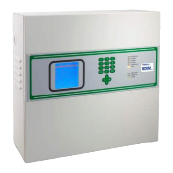
- Page 1 Hydra256 Addressable Gas Detection System Installation and Operation Manual Issue 2 January 2015...
- Page 2 Addressable Gas Detection System Manual Addressable System Manual Issue 2, January 2015...
- Page 3 Tel: +86 10 6787 0335 Website: www.crowcon.com Website: www.crowcon.com Website: www.crowcon.com Website: www.crowcon.com Fax: +86 10 6787 4879 Email: saleschina@crowcon.cn Website: www.crowcon.com Crowcon reserves the right to change the design or specification of this product without notice. Addressable System Manual Issue 2, January 2015...
-
Page 4: Table Of Contents
Addressable Gas Detection System Manual TABLE OF CONTENTS INTRODUCTION ..........................5 1.1) ........................... 5 NIT FEATURES 1.2) ........................ 5 ANEL CONFIGURATION 1.3) ......................6 ECHNICAL PECIFICATIONS INSTALLATION ..........................6 2.1) ............................6 2.1.1) ..................7 IAGRAM AND PART IDENTIFICATION 2.1.2) ..................... - Page 5 Addressable Gas Detection System Manual 4.4.6) ..........................51 4.5) ............52 ODIFICATION OR CREATION OF A NEW CONFIGURATION FILE 4.5.1) ......................52 YSTEM INFORMATION 4.5.2) ......................53 ENERAL ETTINGS 4.5.3) ..........................54 ONES 4.5.4) ......................54 ODULES VERVIEW 4.5.5) ......................... 57 NPUT ODULES 4.5.6)
-
Page 6: Introduction
Addressable Gas Detection System Manual INTRODUCTION This manual details the procedures required to install, program, operate, test and maintain the Hydra gas detection system. 1.1) Unit features The Hydra is a gas detection control unit designed to meet the widest range of flexibility required by the market. -
Page 7: Technical Specifications
Mount the panel using the four fastening holes on the back of the steel enclosure. Fig. 2.1 a) Hydra256 Connect the three-core mains cable to the power supply board (minimum 1.5mm each core) and secure using the wire clamps. -
Page 8: 1) Diagram And Part Identification
Addressable Gas Detection System Manual Fig. 2.1 b) Power supply and batteries 2.1.1) Diagram and part identification Box version CONTROL PANEL INTERNAL VIEW 1- Power supply (27 Vdc 5A) 7- RS485 bus connections 2- 2 12V 7Ah batteries (not included) 8- Relay output connections 3- RS232 serial port (PC connection) 9- Main board... -
Page 9: 2) Back Panel And Connections
Addressable Gas Detection System Manual 2.1.2) Back panel and connections Back panel Legend Relay 1 per Fault / Relay 1 Fault JP33 JP35 Relay 2 AC Fail JP37 Relay 3 Low Battery Relay 4 Buzzer Repeater JP39 JP34 Relay 5 Alarm level 1 JP36 Relay 6 Alarm level 2 Relay 7 Alarm level 3... -
Page 10: 3) Power Connections
Addressable Gas Detection System Manual 2.1.3) Power connections Control unit back panel Al connettore Jp51 è possibile Jp48 collegare un secondo alimentatore per una maggior affidabilità del sistema 3,15 A To the Jp51 connector it is possible the connection of an auxiliary Power Supply, for a more system reliability Jp51... -
Page 11: Dip-Switch Setting For Bus Communication Protocol And Speed
Addressable Gas Detection System Manual 2.1.5) DIP-Switch setting for bus communication protocol and speed The series of D2 dip-switches must be set for unit compatibility with various gas detector versions and IN and OUT modules. D2=switches Vista posteriore scheda centrale / Main board back view Fig. -
Page 12: Field Device Connections
Addressable Gas Detection System Manual Dip-switches from 4 to 7: not used Dip-switch 8: restore default settings Position Function When turned on, restores unit default settings Normal position 2.2) Field device connections The unit comes complete with two RS485 bus lines (upgradeable up to 4) to which gas detectors are connected. -
Page 13: 1) Gas Detector Positioning
Addressable Gas Detection System Manual Two serial bus modules are fitted as standard. A further two may be added to the spare slots located on the reverse side of the main board (item 9 on Figure 2.1.1). Serial bus module locations are shown on the image below. Serial bus Serial bus module 3 and 4... - Page 14 Addressable Gas Detection System Manual The power supply to the detectors (and IN and OUT modules on the bus) must be connected with a 2-core wire with adequate section based on the number of connected devices, their distance from the power supply and each device’s consumption (please see the technical manual enclosed with gas detectors for this purpose).
-
Page 15: Addressable Output Modules
Addressable Gas Detection System Manual 2.3) Addressable output modules STG/OUT16-S remote modules are field mounted and connected to the panel via RS485 buses. They provide 16 Open Collector outputs (negative switch) with programmable functions to remotely trigger Sirens, Solenoid valves, Relays, etc. Each STG/OUT16-S module can be connected to up to 2 boards and 8 relays that convert the Open Collector output to a powerless exchange contact. -
Page 16: 1) Relay Module
Addressable Gas Detection System Manual 2.3.1) Relay Module The 8-relay expansion board converts the open-collector outputs from the addressable output module into voltage free changeover contact. Up to two relay boards can be connected to each output module. A relay board is directly connected to the output module (J1 connector) and a second relay board is connected to the first. - Page 17 Addressable Gas Detection System Manual Example If the address switches are set in this manner, RSW2 at 0 and RSW1 at D, the corresponding address in decimal number would be 13 (see table 1). Table 1: Conversion from decimal to hexadecimal numbers 248 (*) 249 (*) 250 (*)
-
Page 18: 3) Detector Identification
Addressable Gas Detection System Manual 2.3.3) Detector identification Every detector connected to the control panel is identified by a code which allows its configuration and contains all the principle data required to physically identify it. For example: Numero bus (1-4) (bus number (1-4)) C H N 02001 Indirizzo modulo IN/8 o rilevatore gas... -
Page 19: System Power Up And Operation
Addressable Gas Detection System Manual SYSTEM POWER UP AND OPERATION The chapter explains the procedures for the operation, the commissioning and the maintenance of the control unit Hydra 256. For the programming of the Hydra control panel the PC software is required. 3.1) Power ON After ensuring correct installation of the Hydra... -
Page 20: System States And Operation
Addressable Gas Detection System Manual 3.2) System states and operation The LCD display provides the user with details about the various system states. A few general rules apply at any level as follows: Should there be a list displayed, the page scrolling can be done using the UP/DOWN arrow keys. - Page 21 Addressable Gas Detection System Manual ALARM The alarm condition will be activated according to the settings for each and every input: The activation conditions can be user programmable, although for each detector type (in effect each gas detected) a standard configuration is defined and loaded, when making the settings of a stated input through the PC software.
- Page 22 Addressable Gas Detection System Manual At any access level, by selecting in the main window the 1—Menu and than ACTIVE EVENTS sub menu, it is possible to see the gas detectors in alarm state, or not yet reset. FAULT The fault condition will be activated in the following situations: 1.
-
Page 23: User Levels
Addressable Gas Detection System Manual TEST/MAINTENANCE This state is meant for testing and maintenance purpose. This testing function requires an operation sequence and can be activated for each detector being connected. A user with the OPERATOR or MAINTENANCE level cannot put under TEST/MAINTENANCE more than 50% of the system’s channels and outputs. -
Page 24: 1) Operator Level
Addressable Gas Detection System Manual 3.3.1) OPERATOR level It is the lowest user level. The “Operator” user may only see the system’s configuration. He may browse the system through channels and relays. The “Operator” cannot put under Test or get out of Test mode any detector or parts of the system, nor he can Unset parts of the system, or Set parts of the system previously unset. -
Page 25: 2) Maintenance Level
Addressable Gas Detection System Manual 3.3.2) MAINTENANCE level The “Maintenance” level is the middle user level. Like the “Operator” user, the “Maintenance” user may see the system’s configuration. He may also browse the system through channels and relays. Unlike the “Operator” the “Maintenance” user may also put under Test or take out of Test mode any systems part, and he can Unset parts of the system, or Set parts of the system previously unset. -
Page 26: Active Events
Addressable Gas Detection System Manual Operator level (O) Maintenance level (M) Engineer level (E) ACTIVE EVENT (*) ACTIVE EVENT (*) ACTIVE EVENT (*) EVENT LOG EVENT LOG EVENT LOG PRINT SET PRINTER MODE SET PRINTER MODE ABORT PRINT PRINT PRINT SYSTEM INFO ABORT PRINT ABORT PRINT... - Page 27 Addressable Gas Detection System Manual Or in case just fault situation is present: Fig. 3.5.1 c) Active events screen with fault only In case of a new event, the screen will automatically switch to the Active Events list and the buzzer will sound. Until the event is acknowledged, the user cannot go back to the main screen.
-
Page 28: 2) Event Log
Addressable Gas Detection System Manual RESET Pressing 2 RESET with the cursor on the active event previously acknowledged (the one marked with "X"), this will get reset and the event will disappear from the active events list. As described above, there are two situations: 1. - Page 29 Addressable Gas Detection System Manual Select Period This opens a query asking to select the period to be observed by entering the start and the end date. Fig. 3.5.2 b) Select period dialogue window The date should be introduced in a 2 digit format for day, month and year: “DD/MM/YY”.
-
Page 30: 3) Print
Addressable Gas Detection System Manual ALARMS Choosing the Alarms LOG option enters the Alarm events list. Using the up/down arrow keys one may search in the Alarm event log FLT & SYSTEM Choosing the Fault & System LOG option enters the faults and system events list. Using the up/down arrow keys one may search in the Flt &... -
Page 31: 6) System Info
Addressable Gas Detection System Manual Fig. 3.5.5) Set Printer Mode option 3.5.6) SYSTEM INFO At any user level, selecting SYSTEM INFO a window will show the information about the hardware and the software versions: Fig. 3.5.6) System Info window 3.6) 2-LOGOUT From the normal mode screen, pressing 2-LOGOUT key, the actual user will logout. -
Page 32: 4-Login
Addressable Gas Detection System Manual 3.7) 4-LOGIN Pressing 4-LOGIN key a login window will ask for the user password, to allow entering one of the three user levels: OPERATOR, MAINTENANCE or ENGINEER level (see the related chapter 3.3 User levels). Fig. -
Page 33: 3-System
Addressable Gas Detection System Manual 3.8) 3-SYSTEM In the main window in Normal mode, at any user level, one may view the system’s configuration details, by pressing 3-System. The Zones screen will appear. The Zones screen shows the list of the defined zones. One may move the cursor up and down by using the up/down arrow keys. -
Page 34: 2) Modules
Addressable Gas Detection System Manual TEST / EXIT TEST This will put to TEST mode or take out of the TEST mode the selected zone. It is possible to put in TEST mode just parts of the system at user level “Maintenance” or “Engineer”. - Page 35 Addressable Gas Detection System Manual Using the up/down arrow keys one may scroll through the list choosing one of the channel and press 3-Relay for the SET / UNSET and TEST / EXIT TEST operations. By the options of the relative screen, unlike the Operator level, the “Maintenance” level and the “Engineer”...
-
Page 36: 4) Detectors (Channels)
Addressable Gas Detection System Manual Fig. 3.8.3 b) Relay details screen in “Engineer“ level Unlike the above, this screen seen as “Engineer” level, allows changing the relay’s timings. See the chapter 4, Configuration for more details. 3.8.4) Detectors (Channels) In the modules screen, moving up and down with the arrow keys through the modules list and pressing ENTER one gets into the detectors screen Fig. - Page 37 Addressable Gas Detection System Manual TEST / EXIT TEST This will put to TEST mode or take out of the TEST (EXIT TEST) mode the selected channel. It is possible to put in TEST mode just parts of the system when user level is “Maintenance”...
-
Page 38: Pc Configuration Software
Addressable Gas Detection System Manual Fig. 3.8.3 a) Detector details screen in “Engineer“ level Unlike the above, this screen seen as “Engineer” level, allows changing the relays timings. See chapter 4-PC Configuration Software for more details. PC CONFIGURATION SOFTWARE 4.1) Introduction The Configuration Software is an easy to handle user interface for each kind of communication with the HYDRA... -
Page 39: Installation
Addressable Gas Detection System Manual 4.2) Installation Insert the CD-Rom and follow the instruction One serial cable is necessary to connect the PC to the Control Panel (see chapter 2.7), either through the standard COM1 or through an USB converter, using any of the USB ports on PC. -
Page 40: 1) Program Homepage
Addressable Gas Detection System Manual 4.3.1) Program homepage Fig. 4.3.c) Program homepage (Administrator level user) New configuration to create a new system configuration Open file to open an existent configuration Serial port to set a PC serial port for data transfers to and from the connected CPU Test to test PC serial >... -
Page 41: Program Menu
Addressable Gas Detection System Manual 4.4) Program menu The various program functions are only visible if the user who logged in has the permissions to use them. Configuration software includes plausibility checks on edited and new parameters. The following chapters list program menus and describe their functions. 4.4.1) File Fig. - Page 42 Addressable Gas Detection System Manual An event log file previously loaded and saved in the specific folder can be opened from “Open Event Log File”. Fig. 4.4.1 d) *.elog event log file folder Fig. 4.4.1 e) Event log For information on reading the event log, see: Menu: Communication submenu: Upload Event Log from CPU.
- Page 43 Addressable Gas Detection System Manual The event log displayed from the SD card is not formatted like the previous one, downloaded from the CPU to the PC. Fig. 4.4.1 f) Event list in the SD card Click “Save” to save changes to the system. Click “Duplicate”...
- Page 44 Addressable Gas Detection System Manual Fig. 4.4.1 h) System file comparison window Click “Save As” to save the system file with a new name Click “Close” to close the open system file Click “Exit” to exit the HYDRA256program Addressable System Manual Issue 2, January 2015...
-
Page 45: 2) Settings
Addressable Gas Detection System Manual 4.4.2) Settings Fig. 4.4.2 h) System file comparison window Click “Serial Port” to select the PC serial port to upload and download data Click “Language” to select the HYDRA256software language. When creating or editing a system configuration, remember to click “Save” before changing the program language or all changes will be lost. - Page 46 Addressable Gas Detection System Manual The first time the program is used after installation, the only user installed is Sensitron with default password 543210. Sensitron is an administrator level user which is the highest level and permits access to all program functions. The Name, password and Contact Info can be changed for the Sensitron user but not the username (sensitron) and level (Administrator).
- Page 47 Addressable Gas Detection System Manual Flag the various boxes to enable the relevant function for the user. Click “Set Default”, according to the user level being set (Level 1, 2 or 3), a preset selection of enabled functions are automatically assigned to the user (which can always be edited).
-
Page 48: 4) Communication
Addressable Gas Detection System Manual 4.4.4) Communication Fig. 4.4.4 a) Communication Menu The “Communication” menu includes options for data transfers between the PC software and the HYDRA256control panel Note. The two devices must be connected in order to transfer data between the PC and HYDRA control panel. - Page 49 Addressable Gas Detection System Manual Fig. 4.4.4 b) Serial password entry window The default password is 000000 but can be changed by clicking “Change Control Unit Password”. Warning. The control panel cannot be accessed if the new password is lost Fig.
- Page 50 When data is uploaded, the system file is automatically saved in the specific PC folder. Fig. 4.4.5 f) Open an existent system file The default folder is: c:\Documents and settings \ user \ Documents \ HYDRA256\ Configs “Up Load Event Log from CPU” lets you upload the event log file from the CPU.
- Page 51 After entering the password, the event log file starts uploading and this operation may take up to one minute. When uploaded, in addition to being automatically saved in the PC default folder: c:\Documents and settings \ user \ Documents \ HYDRA256\ Logs, events are also displayed in the specific window.
-
Page 52: 5) Reports
Addressable Gas Detection System Manual Event More detailed description of the event type Value Gas concentration value (for an alarm event) Unit Gas detector unit of measure User User ID for user events (Ack, Reset,Login etc.) Device Hardware device that generated the event (input module, Gas detector, Output module, etc.). -
Page 53: Modification Or Creation Of A New Configuration File
Via the “Open” command in the “File” menu existing configuration files will be indicated and may be chosen and opened. If some parameters at the HYDRA256 shall be modified, this has to be carried out as described in the following chapters. -
Page 54: 2) General Settings
Addressable Gas Detection System Manual 4.5.2) General Settings Fig. 4.5.1.b) General Settings screen details In the “General Settings” it is indicated: “Warm Up Time” the warm-up time for the system after which it passes over to measuring mode (from 2 to 10 minutes; default 3 minutes) “BUS Architecture”... -
Page 55: 3) Zones
Addressable Gas Detection System Manual 4.5.3) Zones Fig. 4.5.3) Zones definition screen The creation of zones is not mandatory for the reliable function of the gas detection system. It is an aid for the user to indicate useful additional information in the case of alarms. - Page 56 Addressable Gas Detection System Manual Fig. 4.5.4 a) Module Overview screen RIO Input Modules STG/IN8 analog input modules installed in the system are set in RIO Input Modules. Click Add RIO Input Module to open the window shown in Fig. 4.5.4 b. Fig.
- Page 57 Addressable Gas Detection System Manual Sensors Gas Detectors installed in the system and directly connected on the CPU loop (RS485 bus) are set in “Sensors”. Refer to chapter 2-Installation for further information. Click Sensors to open the window shown in Fig. 4.5.4 c. Fig.
-
Page 58: 5) Input Modules
Addressable Gas Detection System Manual RIO Output Module STG/OUT16 output modules installed in the system are set in RIO Output Module. Click Add RIO Output Module to open the window shown in Fig. 4.5.4 b. Fig. 4.5.4 c) Module configuration screen Zone Zone where the module is installed Loop... - Page 59 Addressable Gas Detection System Manual The Channel Map gives a quick overview of how many Input modules and detectors are programmed in the HYDRA configuration and these are defined. Different colours represent different characteristics like not defined, redundant or non redundant channels or if the channels are connected directly or by Remote RIO Input Modules.
- Page 60 Addressable Gas Detection System Manual Channel Manage Fig. 4.5.5 c) Channel details screen Specifying a new input-channel An input channel is specified by the combination of three different drop down lists. The “Profile” specifies the measurement task: e.g. %LEL monitoring , toxic , toxic STEL , oxygen deficiency. Related to the profile are rules for the setting options for the related channels ...
- Page 61 Addressable Gas Detection System Manual average alarms will be activated. In the LEL profile average alarms are forbidden and therefore the option is not visible in the related alarm window. The “Gas Type” represents the list of gases belonging to the related “Profile”.
- Page 62 Addressable Gas Detection System Manual Screen for “Alarm Settings” Fig. 4.5.5 d) Alarm settings details in case of instantaneous thresholds In the submenu “Alarm Settings” the threshold values for all three alarm levels can be modified within a specified range indicated by the red bar and a sliding control. The left arrow going upwards is indicating the “increasing alarms”...
- Page 63 Addressable Gas Detection System Manual Modification of alarm levels The values can be modified in steps by touching the – on the left or the + on the right side of the horizontal alarm bar or by typing the numbers into the numeric indication on the right side.
- Page 64 Addressable Gas Detection System Manual The values can be modified in steps by touching the – on the left or the + on the right side of the horizontal alarm bar or to the left within the range of the red bar or by typing the numbers into the numeric indication on the right side.
- Page 65 Addressable Gas Detection System Manual If the system requires a very high security level, two detectors are to be placed at each measuring point. “Profile” and “Gas Type” have to be identical. The two detectors may be of the same type or of two different types e.g. in the LEL profile a Pellistor and an infrared (IR) detector.
- Page 66 Addressable Gas Detection System Manual If the chosen redundant channel is already programmed and differs from the first one (example: current channel is number 5 from RIO 2 and the redundant channel is number 1 from RIO 2), a warning (4.5.5 h) will be indicated. In this case, by pressing OK, the alarm settings of the first channel shall be taken over for both channels.
- Page 67 Addressable Gas Detection System Manual Redundant channels with different detector models (divers redundancy) Fig. 4.5.5 i) Redundancy defined for two different detector models For the same area to be covered, when redundancy is being applied, one may set as redundant two channels having installed different models of detectors, if these are both for the same gas and have the same the thresholds settings.
-
Page 68: 6) Output Modules
Addressable Gas Detection System Manual 4.5.6) Output Modules Via the menu “Output Modules”, the characteristics of remote output modules STG/OUT16 being part of the system are enabled and programmed. RIO Output Map Fig. 4.5.6 a) RIO Output Map screen The RIO Output Map gives a quick overview of how many output modules (RIO Out STG/OUT16 modules with or without extension relay board) are presently used in the HYDRA... - Page 69 Addressable Gas Detection System Manual Fig. 4.5.6 b) Output popup window with the parameters RIO Output Manage Fig. 4.5.6 c) Outputs details screen – Events tab Addressable System Manual Issue 2, January 2015...
- Page 70 Addressable Gas Detection System Manual The “Selected Events” lists all events, which will trigger the relay e.g.: Alarm 2 of at least one of the channels 1, 2, 3 and so on of RIO module 1. The “Filter” buttons on the left side allow reducing the list of shown events. The list will only contain the selected event type.
- Page 71 Addressable Gas Detection System Manual Voting Function Fig. 4.5.6 e) Output events details screen – example of a VOTING combination Example: Relay 4 of Module 3 is configured. On the lower left side “Alarm 1” is marked. Therefore in the list of events only the alarm 1 for all channels is indicated.
- Page 72 Addressable Gas Detection System Manual Outputs Redundancy Fig. 4.5.6 e) Redundancy tab in the outputs definition screen The relay 4 of module 3 has been defined. After finishing the configuration of the relay the TAB “Redundancy” is chosen. Because actually no redundant relay is specified, the information within the TAB is empty (bottom left of Fig.
- Page 73 Addressable Gas Detection System Manual There will be chosen the not defined output 2 from module 3. After touching “Accept” the following warning (see Fig. 4.5.6 f below) will be indicated. Fig. 4.5.6 f) Typical warning when choosing as redundant a non defined output If the chosen redundant channel is already specified and differs from the first one (also channel 6 from module 3), a slightly different warning (Fig.
- Page 74 Addressable Gas Detection System Manual When pressing OK, the configuration for the “Current Relay” will be taken also for the redundant relay. In the figure below Output 4 of Module 3 is indicated as redundant to Output 6 of Module 3. Fig.
- Page 75 Addressable Gas Detection System Manual Outputs programming by using “Combined Events” Fig. 4.5.6 i) Outputs details screen – Combined Events tab For a common alarm a maximum of 16 events can be combined with the “OR” function. If a common alarm is required for more than 16 events, the menu function “Combined Events”...
- Page 76 Addressable Gas Detection System Manual When choosing the button “Add New Combined Event” a pop up window will be opened. Fig. 4.5.6 l) Combined events management Fig. 4.5.6 m) Combined events management in in Voting In the Fig. 4.5.6 l a voting is specified; in Fig. 4.5.6 m the events are combined by A description should be added to identify the new events in the list of combined events.
- Page 77 Addressable Gas Detection System Manual Outputs “Operation Mode” There are three options for the output Operation Mode Steady follows the course of the alarm; alarm activated, output activated after a possible activation delay; alarm restored, output low after a possible de-activation delay. Output operation mode Steady activated until the channel restore +...
-
Page 78: Warranty
‘crowconsupport.com’, along with a returns label, alternatively we can ‘email’ you a copy. Instruments will not be accepted for warranty without a Crowcon Returns Number (“CRN”). It is essential that the address label is securely attached to the outer packaging of the returned goods. - Page 79 Addressable Gas Detection System Manual Units returned to Crowcon as faulty and are subsequently found to be ‘fault free’ or requiring service, may be subject to a handling and carriage charge. Warranty Disclaimer The guarantee will be rendered invalid if the instrument is found to have been altered, modified, dismantled, or tampered with.
Need help?
Do you have a question about the Hydra256 and is the answer not in the manual?
Questions and answers