Table of Contents
Advertisement
Quick Links
Advertisement
Table of Contents

Summary of Contents for Maker Factory MF-4992453
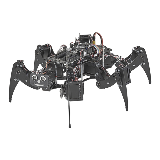
- Page 1 Operating Instructions Hexapod Robobug Complete Set Item no. 1664151...
-
Page 2: Table Of Contents
Table of Contents Page 1. Introduction ............................................4 2. Explanation of symbols .........................................4 3. Intended Use ............................................4 4. Package Contents ..........................................5 5. Product Description ..........................................5 6. Features ...............................................6 7. Safety Instructions ..........................................7 8. Required accessories ...........................................8 9. General notes ............................................9 10. Preparatory work ..........................................10 a) Application of the screw locking lacquer ..................................10 b) Ball bearings and cylindrical pins ....................................10 c) Power Supply .......................................... - Page 3 Page 27. Disposal ..............................................64 a) Product ............................................64 b) Batteries/Rechargeable Batteries ....................................64 28. Technical Data ............................................65 a) General information........................................65 b) Control electronics ........................................65 c) Gamepad ............................................65...
-
Page 4: Introduction
1. Introduction Dear customer, Thank you for purchasing this product. This product meets the requirements of current European and national guidelines. We kindly request the user to follow the operating instructions to preserve this condition and to ensure safe operation! This user manual is part of the product. -
Page 5: Package Contents
4. Package Contents • Hexapod Robobug Mechanical Kit • 18x Servos • Hexapod Robot Board • Gamepad for control • Small parts (e.g., jumpers, battery plug XT30) • Quick guide Latest Operating Instructions Download the latest operating instructions via the link www.conrad.com/downloads or scan the QR code shown here. Follow the instruc- tions on the website. -
Page 6: Features
6. Features • Simple construction • Easy programming with Arduino™ (Arduino™ library available) • Firmware based on Arduino™ • Onboard locomotion controller ATmega2560 for leg control (Arduino™ MEGA compatible) • 18x high performance digital servos with metal gear, double ball bearings • High-quality aluminium and plastic parts • Legs with double ball bearings • Control via gamepad (included in delivery) and user board commands... -
Page 7: Safety Instructions
7. Safety Instructions Please read the operating instructions carefully and pay particular attention to the safety instructions. We do not assume liability for any injuries/material damages resulting from failure to observe the safety instructions and the information in these operating instructions regarding the proper use of the product. -
Page 8: Required Accessories
8. Required accessories • NiMH battery; 5 cells, min. 3700 mAh (e.g., Conrad item no. 1784857) • Charger (e.g., Conrad item no. 1413029 or 1413030) • Adapter cable XT30 (e.g., Conrad item no. 1785258) • Batteries (2x AAA/Micro) (e.g., Conrad item no. 658010) • Screw locking (e.g., Conrad item no. -
Page 9: General Notes
9. General notes • Take enough time for the assembly. Too much hurry leads often to mistakes which can damage the components or cancel out the time gained by extensive reworking. • The workplace should be sufficiently large and clean so that the various components and assemblies can be easily removed and assembled. • It is essential that you observe the pictures during assembly. Here the assembly locations and the correct alignment of the components are shown. • All mechanical components of the kit are manufactured very precisely. -
Page 10: Preparatory Work
10. Preparatory work Before the robot is assembled, some parts are prepared. This makes the actual assembly easier and faster. a) Application of the screw locking lacquer In the following instructions, some screws should optionally be secured with a screw lock. This is pointed out accordingly in the text. We recommend that you only apply the screw lock after the robot has been completely assembled and calibrated. -
Page 11: C) Power Supply
c) Power Supply In assembling the Robobug you will need the battery for the power supply, in order to be able to move the leg servos in the middle position, to align the legs and later to install the firmware, which is responsible for running the robot in the next work steps. For all this work, the Robobug needs a power supply. The right power supply is crucial for the safe and trouble-free operation of the Robobug. The Robobug is designed for a NiMH battery with 5 cells and a capacity between 3500 - 5000 mAh. -
Page 12: Transferring The Firmware
11. Transferring the Firmware On delivery, no firmware is installed on the Hexapod Robot Board. The firmware must first be transferred during initial commissioning. This is done via the Arduino IDE. The following description shows you the procedure for transferring the firmware. In the following chapters you will transfer different programmes to the Hexapod Robot Board. The procedure is identical except for the selection of the respective program. When transferring the firmware, the Hexapod Robot Board must be connected to the power supply (battery)! Make sure that the battery is fully charged before transferring the firmware or programmes. a) Installing the driver Connect the "PRG-M" port of the Hexapod Robot Board to a free USB port on your computer. Windows will now attempt to install a new driver. Typically, Windows will automatically download and install the drivers from the Internet, since the driver for the "FTDI"... - Page 13 Now install the Hexapod library. It can be found in the download bundle under "\Library-Demos\Maker-Factory-Hexapod-V1.1.zip". Select the menu item "Sketch\In- clude Library\Add .ZIP Library..." in the Arduino IDE. If you update the library later, you have to delete the old library first, otherwise the Arduino IDE will report an error! Figure 9 After you have installed the library, you will find two folders named "Locomotion" and "User-Boards" in the menu item "\File\Examples\Maker-Factory-Hexapod-Vx.x". The folder "Locomotion"...
- Page 14 To test if everything works, transfer the sample programme "\User-Board\Locomotion\ LEDs". After successful transmission, the programme causes the blue "LIVE-LED" and the red "USER-LED" to flash alternately. To transfer the programmes, the battery must be plugged into the Hexapod Robot Board! After selecting the "LEDs" programme (also called Sketch in Arduino) a new Arduino IDE window opens with the "LEDs"...
-
Page 15: Preparing The Leg Servos For Installation
12. Preparing the leg servos for installation Before you install the leg servos, you must move them to the centre position. This means moving the servos to the mechanical middle position using the Hexa- pod Robot Board and the "ServoCenter" program. This is the starting position for assembly. First unpack all 18 servos;... - Page 16 Figure 17 Figure 17 shows the pin headers to which the servos are connected. The pin strips labelled SA0 to SA5 do not carry a control signal. This connection remains unassigned and can later be used for proper extensions such as leg contact sensors.
- Page 17 Functional description of a servo Servos have electronics, a motor and a potentiometer. The potentiometer picks up the mechanical position of the servo and forwards it to the servo electronics. The electronics in the servo compares the given position (nominal value, in our case the pulse width given by the locomotion controller) with the pulse width of the servo electronics (set via the potentiometer, actual value).
-
Page 18: Assembling The Mechanical Parts
13. Assembling the mechanical parts The following illustrations illustrate the mechanical assembly. Caution! When tightening the plastic screws, make sure that they are not screwed too tightly into the plastic and that the plastic holders are not damaged! If you remove a screw from a plastic part and then screw it in again, first turn the screw anticlockwise until you notice that the screw "engages". At this point the screw is "engaged" in the existing thread. The screw can then be easily screwed into the thread that has already been created during the first screwing in. If the self-tapping plastic screw is screwed in without using this method, a new thread may occur. This weakens the material and the tensile strength as well as the hold are no longer guaranteed. - Page 19 The Coxa servo and femur servo holder must be mounted 6 times (3 left and 3 right). First insert a servo into the holder and screw it on. Only then is the second servo plugged in and screwed in. The servo cable of the Coxa servo is inserted through the round opening at the top and the servo cable for the femur servo is inserted through the large oval opening as with the U-angle mounting.
-
Page 20: B) Mounting Of Bearings
b) Mounting of bearings Required tool: 10 mm hexagon socket (from a socket wrench set) or comparable tool as a tool for mounting the bearings Push the bearings into the aluminium parts as shown in the following illustrations. Here a hexagon socket wrench or a comparable tool can be helpful. Do not use rough force, this can damage the base plate and the ball bearings! Avoid tilting, with some sensing the position can be pressed in without great resistance. - Page 21 The femur counter bearing must be assembled a total of 6 times. Figure 26 Figure 27 shows how you can push the bearing into the aluminium part by hand. The bearing should snap into the bore provided with a bold push. Figure 27 Make sure that the edge of the bearing is flush with the aluminium part.
-
Page 22: C) Mounting The Servo Disks
c) Mounting the servo disks Mount the servo disks as described in the following illustrations. Use two M2 screws + nut for each servo disk. The other holes remain free! These screws (all M2) are now already provided with a screw lock. Required tool: PH1 Phillips screwdriver Small flat nose pliers or wrench for M2 nut (SW4) - Page 23 The femur servo mount must be mounted a total of 6 times. Figure 31 Figure 32...
-
Page 24: D) Mounting The Spacer
d) Mounting the spacer Next, screw together the spacers (30 mm long) for the legs, top and bottom plates as shown in Figure 33. A total of 12 screwed spacers are required. Required tool: 2x SW 5.5mm open-end wrench Figure 33 Then fit a screwed spacer to each femur counter bearing. Insert the threaded side through the counter bearing and fix it with an M3 nut. It is sufficient if the spacers are only tightened by hand. -
Page 25: E) Mounting The Servos On The Top Plate
e) Mounting the servos on the top plate Mount the servos with the M3 screws (M3 x 6 mm, large head diameter) as shown in Figure 36. For mounting the servos with the servo discs, always use the M3 x 6 mm screws (servo mounting screws) with the larger 6 mm head is used. The M3 x 6 mm screws with the smaller 5 mm head are used for the spacers! Insert the servos into the teeth of the previously mounted servo disks. - Page 26 Figure 37...
-
Page 27: F) Mount Bottom Plate
f) Mount bottom plate Mounting the bottom plate requires some skill. Place the top plate with its back on the table as shown in Figure 38. Push the cylinder pins of the base plate into the plastic holders of the top plate, starting from the front or rear, all the way round. Do not push the pins completely in the first time, but repeat the working step and press the cylinder pin only a few millimetres into the plastic each time it circulates. This prevents the component from becoming strained! Place an underlay, such as a cardboard box, between the component and the table so that you do not scratch the table with the screw heads! The... - Page 28 Figure 39 shows the top side of the robot! Figure 39 Figure 40 shows how the dowel pins are only slightly pressed in to fix them in the plastic. Only when all the dowel pins have been fixed in the holes of the plastic holders are they pressed in at a distance (2.5 mm). To achieve the correct distance, place the Hexagon key between the bearing and the plastic holder and press the cylinder pins into the plastic holder with moderate force.
-
Page 29: G) Mounting The Receiver And Hexapod Robot Board
g) Mounting the Receiver and Hexapod Robot Board Now the radio receiver for the gamepad is connected to the robot board and mounted. The receiver is fixed to the underside of the robot board with the supplied double-sided adhesive tape. The receiver and the connection cable must first be connected to each other. Connect the wide receiver plug to the receiver. When connecting the receiver to the robot board, make sure that the polarity of the connectors is correct. Required tool: Scissors PH2 Phillips screwdriver Open-end wrench SW 5.5 mm Plug the cable into the receiver as shown in Figure 42. The "POWER"... - Page 30 Now connect the cable to the robot board. The colours are combined in the plugs to 3 wires each. From left (MicroSD card holder position) to right (battery plug position): White, grey, purple -> White points to outer edge of board Blue, green, yellow ->...
- Page 31 Now mount the robot board with the four 15 mm spacers. The threaded side of each spacer is inserted into the top plate and fastened with an M3 nut. Do not tighten the M3 nuts too tightly as this will allow you to readjust them easily to mount the PCB without tension. Only when the board has been fixed to the spacers with four screws M3 x 6 mm (small head diameter 5 mm), tighten the M3 nuts. In this way you can align the board cleanly.
-
Page 32: H) Mounting The Legs
h) Mounting the legs Try to mount the legs the as well as you can. Minor deviations do not play a role and cannot be avoided by the mechanical tolerances and by the coarse teeth of the servo disks. The legs will be exactly adjusted later by software! Figure 48 (see also Figure 20) shows the basic configuration of a Hexapod leg. It should be noted that the thigh (femur) is aligned parallel to the ground ("ground"... - Page 33 First mount the thighs (“femur”) as shown in Figure 50. Screw the thighs to the servos (M3 x 6 mm screws, large head diameter 6 mm). Then assemble the legs “tibia” and fix them with the M3 x 6 screws (large head diameter 6 mm). It is helpful to lift the robot with the help of a cardboard box. If you have a 3D printer, you can also print out the robot stand.
- Page 34 Now mount the counter bearings. The U holder has two holes, use the hole facing the cable opening. When pressing in the dowel pins, proceed in the same way as when pressing in the dowel pins of the base plate. The distance between the bearing and the plastic part here is 1.5 mm.
-
Page 35: I) Laying The Cables
i) Laying the cables Lay the cables as shown in the illustrations. Use the supplied cable ties for this purpose. After the cable ties have been tightened, cut off the protruding part of the cable tie. A clean cable laying gives the robot a very high-quality appearance! As long as you have not finished aligning the cables, you should not tighten the cable ties too tightly. This way you can make small corrections easily. - Page 36 Figure 58 Figure 59...
- Page 37 Figure 60 Illustration_61 Figure 61...
- Page 38 Figure 62...
-
Page 39: J) Installing The Battery
j) Installing the battery The battery is mounted edgeways with the supplied Velcro fastener as shown in the illustrations. To do this, shorten the Velcro fastener to approx. 25 cm. Tighten the Velcro so that the battery has a firm grip on the battery plate and cannot slip during operation. Figure 63 Then run the cable through the top plate as shown in Figure 64a. Screw the battery retaining plate to the lower plate. -
Page 40: K) Mounting The Rubber Feet
k) Mounting the rubber feet Slide the supplied rubber feet onto the ends of the legs. You can also secure the rubber caps with some glue (e.g., Uhu All Purpose Glue or ® similar) so that they are not lost during operation. The rubber feet not only secure a good grip on the ground, but also ensure that the aluminium legs do not scratch the ground (floor, table etc.). -
Page 41: Transferring The Firmware
14. Transferring the Firmware After you have finished the mechanical assembly of the robot, the "Locomotion Firmware" can be installed on the robot board. This is responsible for the run- ning behaviour of the robot. Check the following before transferring and switching on the robot board: • Are all servos connected correctly (polarity)? • Are all servos mechanically in the middle? • Is the Gamepad controller connected? • Is the battery sufficiently charged? • Is there enough space available for the robot, even in the event of a malfunction? Now connect the battery to the robot board, if not already done. -
Page 42: Controlling With The Gamepad
15. Controlling with the Gamepad After you have transferred the "motion firmware" to the Locomotion controller (see chapter 14), you can control the robot with the gamepad. With the included gamepad, all functions of the Locomotion controller are immediately available to you after commissioning and the robot can be moved similar to a remote- controlled car without you having to create your own programme beforehand. To check the settings comfortably and quickly, it is advantageous to operate the robot with the gamepad. - Page 43 Detailed description of the gamepad functions: 1 Make the robot stand up and sit down (toggle function) 2 System reset 3 Switch the robot on/off after the gamepad has been activated with the key (15) 4 Switch on/off balance mode (toggle function) 5 Right Thumb joystick (turn on the spot, turn in rotate and translate mode and change the height of the robot) 6 LED lights green when the connection to the robot has been established 7 Left thumb joystick (forward/backward, in rotate and translate mode forward/backward and lateral movement).
-
Page 44: Calibrate Legs
16. Calibrate legs To adjust the legs exactly, use the programme "Terminal" (if you work with the Windows operating system) or alternatively, the Arduino IDE Terminal. The aim now is to adjust the legs into an exact basic configuration. When assembling the mechanics, you will not be able to bring the legs 100% into the basic configuration due to the teeth of the servo disks and the mechanical tolerances. You can use this tool to compensate for these deviations. Figure 69 shows how the basic configuration should look for each leg. Figure 69 The fictitious red lines show how to align the leg. The thigh "femur" must be aligned so that it is parallel to the floor. The tibia is perpendicular to the floor and makes a 90° angle at the thigh. If the robot is placed on a flat surface with a mounting aid as shown in the illustration, the distance between the table and the centre of the M3 cross screws can easily be measured with a ruler. - Page 45 Calibrating legs with PC If you are using Windows, you can use the "Terminal" program. The programme is located in the "Terminal" folder. If you are using MAC OS or Linux, you can skip this part and continue with the section "Leg calibration with the Arduino IDE".
- Page 46 The following text appears in the terminal window. PS2 Init: 0 Maker Factory Hexapod Monitor O - Enter servo offset mode Send an "O" to the robot board by writing "O" in the transmission line and then pressing the Enter key. The robot will now "wiggle" with the chosen servo in the setting.
-
Page 47: Using User Boards
17. Using user boards The robot board can be equipped with different user boards to extend the functionality. Possible user boards are e.g., Arduino UNO, NodeMCU or compatible boards. These can be plugged directly onto the robot board. With the software library described in the next chapter you can send control commands from the user board to the locomotion controller or read values from the locomotion controller. - Page 48 • Single-Board-Computer (SBCs) and other Boards The robot board offers the possibility to mount an SBC like e.g., a Raspberry Pi 2/3 or compatible via board spacers. SBCs with a different hole spacing can be easily mounted with a self-made adapter board. Here the robot board offers enough space for proper extensions. The pin header shown next to the "ISP-U"...
- Page 49 Figure 77 shows the robot and a Raspberry Pi 2 mounted on three 25 mm long circuit board spacers. The holes for mounting are already present in the robot board. The connection between the Raspberry Pi and the robot board was made using jumpwire connectors. The cables of the jumpers were placed under the Raspberry Pi to get a clean wiring.
-
Page 50: Demo Programmes
18. Demo Programmes To use the user boards easily and comfortably, use the Maker-Factory Hexapod library. This library was already installed at the beginning of this manual. The provided examples show the use of the user boards and the functionality of the Arduino Hexapod library. When using user boards that are not Arduino compatible (like SBC), look at the file "Hexapod_Lib.h". This file shows how the communication between the user board and the locomotion controller works. This will serve you as an example for developing your own function library. To do this, unpack the ZIP file "\Library- Demos\Maker-Factory-Hexapod-Vx.1.zip"... - Page 51 Brief description of the supplied examples for user boards: In the folder "User-Boards" you will find the examples for Arduino UNO and NodeMCU or compatible boards. Before use, change the Arduino IDE to the correct Arduino board! Also, read the information in the comments to the respective examples! The "Hexapod_Lib.h" contains all functions that are sent and received from the UserBoard to the Locomotion-Controller. For the advanced developer it is worthwhile to have a look inside or to extend these with proper functions.
- Page 52 • "ReadValues_01" The example shows how you can send and read data between locomotion controller and user board without a library. This example is well suited as a basis for using SBC. However, experience in programming is necessary! The terminal baud rate is 115200 baud. • "ReadValues02"...
-
Page 53: Overview Of The Connections And Components Of The Robot Board
19. Overview of the connections and components of the robot board Figure 79 Lay down the robot board as shown in the illustration to get an overview of the connector options. You can also find the circuit diagram for the board at www.conrad.com on the product website. The Hexpod robot board has the following connectors and components: XT30 connector for connecting the battery that powers the board. - Page 54 5V & GND Stabilised 5 V/DC/1000 mA are available at these pins. This connector is available for proper extensions and experiments ("5V" = positive pole, "GND" = negative pole). 3.3V PWR-LED The red LED indicates that the 3.3 V voltage/power supply is working. It lights up when a power supply is connected to the BAT connector.
-
Page 55: Schematic System Overview (Block Diagram)
20. Schematic system overview (block diagram) The diagram shows schematically the internal wiring and the interaction of the individual components of the robot board and serves as an aid for programming. Figure 80... -
Page 56: Pan Unit
21. Pan unit Optionally, an additional servo can be purchased, and the robot can be extended by a pan unit (swivel unit). The complete kit already includes an additional U-holder with accessories. Sensors or faces, for example, can be mounted on this. Please also have a look at the additional downloads for the Robobug. In the download area there are various 3D printable files available to expand your robot. The Pan unit is mounted in the same way as the legs are. Figure 81 shows the fully assembled Pan unit on the robot. -
Page 57: Pin Assignment Of The User Boards
22. Pin assignment of the user boards Locomotion controller (ATmega2560) Arduino user board Port Arduino Port Arduino ADC2 ADC3 MISO MOSI SS_SD IR-DAT RxD_U TxD_U NodeMCU user board Port Arduino ADC0 GPIO14 GPIO12 GPIO13 GPIO15 RxD_U GPIO0 TxD_U GPIO2 PS2_DAT PS2_CMD PS2_SEL PS2_CLK... -
Page 58: Parts List
23. Parts list Some components such as screws, nuts and other small parts are included in the scope of delivery in larger quantities than necessary. These are used as replacements if, for example, a screw is lost during assembly. Figure 82: 1x upper plate Figure 83: 1x lower plate Figure 84: 1x battery plate Figure 85: 3x leg "Tibia"... - Page 59 Figure 86: 12x leg "Femur" Figure 87: 3x "Coxa/Femur" servo mount right Figure 88: 3x "Coxa/Femur" servo mount left Figure 89: 7x U-angle "Tibia", servo holder...
- Page 60 Figure 90: 18x servo discs Figure 91: 18x leg servos Figure 92: 1x Robobug board Figure 93: 1x PS2 compatible gamepad...
- Page 61 Figure 94: 1x PS2 Gamepad compatible receiver Figure 95: 1x 9-pin connection cable for receiver Figure 96: 1x Velcro fastener for fastening the battery pack Figure 97: 1x Double-sided adhesive tape (servo tape) for mounting the receiver Figure 98: 19x ball bearing with dowel pin for leg counter bearing Figure 99: 25x cable ties for cable fixing...
- Page 62 Figure 100: 1x XT30 battery plug to assemble your own battery Figure 101: 24x 30 mm M3 spacer for legs and upper and lower plate Figure 102: 4x 15 mm M3 spacer for PCB mounting Figure 103a: 16 x Screw M3 x 6 mm PH2 (small head diameter 5 mm) for spacers and PCB mounting Figure 103b: 18 x Screw M3 x 6 mm PH2 (large head diameter 5 mm) for spacers and PCB mounting Figure 104: 72x Self-tapping screw M2.9 x 10 mm for servo mounting Figure 105: 2x M4 x 6 mm PH2 Screw for battery mounting...
-
Page 63: Faq
24. FAQ Error compiling the examples If there are problems compiling the firmware: The provided firmware as well as the examples were developed with Arduino version 1.8.3. Alternatively, you can download it from www.arduino.cc. Sound output too low Check the setting of the "Vol." trimmer. Build a small "speaker box" into the robot board speaker. This increases the volume and improves the sound consider- ably. -
Page 64: Cleaning
The robot carries out a reset after switching on or getting up. • Make sure that the battery is fully charged. • Is the battery connection cable too thin (< 1.5 mm²) or longer than 20 cm? • Is the battery plug soldered on cleanly? • If the battery is too small, it cannot supply the necessary operating current for the servos. - Page 65 28. Technical Data a) General information Body length ............... 280 mm Body height without PCB .......... 65 mm Body width without PCB ........... 150 mm Coxa length .............. 50 mm Femur length ............75 mm Tibia length ............... 115 mm Weight ..............
- Page 68 This is a publication by Conrad Electronic SE, Klaus-Conrad-Str. 1, D-92240 Hirschau (www.conrad.com). All rights including translation reserved. Reproduction by any method, e.g. photocopy, microfilming, or the capture in electronic data processing systems require the prior written approval by the editor. Reprinting, also in part, is prohibited. This publication represent the technical status at the time of printing. Copyright 2018 by Conrad Electronic SE.
Need help?
Do you have a question about the MF-4992453 and is the answer not in the manual?
Questions and answers