Table of Contents
Advertisement
Quick Links
Advertisement
Table of Contents

Related Manuals for Perfect Prime CO2512


Summary of Contents for Perfect Prime CO2512
- Page 1 Datalogger Carbon Dioxide Meter CO2512 Instruction Manual...
-
Page 2: Table Of Contents
CONTENTS 1. General Description ................. 2 2. Safety Information ................2 3. Features ..................3 4. Specifications ................4 - 5 5. Symbol Definition and Button Location ......... 6 - 7 6. Button Instructions 6.1 Power ON/OFF and Back-Light button .......... -
Page 3: General Description
1. GENERAL DESCRIPTION/ 2. SAFETY INFORMATION GENERAL DESCRIPTION Thank you for choosing our Carbon Dioxide (CO2) Meter. To ensure the safety and the best performance of this instrument, we recommend you to read and follow the manual carefully before operation. Data can be stored in the meter or directly saved on a computer through PC interface. -
Page 4: Features
3. FEATURES CO2, humidity and temperature sensors. • Dual wavelength NDIR CO2 sensor (Non-Dispersive Infrared) for • superior stability. User operated CO2 calibration. • Data Hold & Max/Min/STEL/TWA function. • Adjustable auto power o timer. • Internal CO2 alarm buzzer. •... -
Page 5: Specifications
4. SPECIFICATIONS CO2 SENSOR: Type Non-dispersive infra-red (NDIR) Measurement range 0~30000 ppm Accuracy ± (75ppm+3% of reading ) (0~5000 ppm) ± (150ppm+5% of reading ) (5001~30000 ppm) Resolution 1 ppm Response time 20 s Sampling rate RELATIVE HUMIDITY SENSOR: Measurement range 0 ~ 100% Accuracy ±... - Page 6 4. SPECIFICATIONS TEMPERATURE SENSOR: Measurement range 0 to 50°C (32 to 122°F) Accuracy ±1.0°C (@23 ± 5°C) (in still air) Resolution 0.1°C /0.1°F Response time: (1/e) 10 s Temperature Coe cient: For ambient temperatures from 0°C ~ 18°C and 28°C ~ 50°C, add the following tolerance into the accuracy spec for each °C ambient below 18°C or above 28°C: 0.01% of reading + 0.03°C 0.01% of reading + 0.06°F...
-
Page 7: Symbol Definition And Button Location
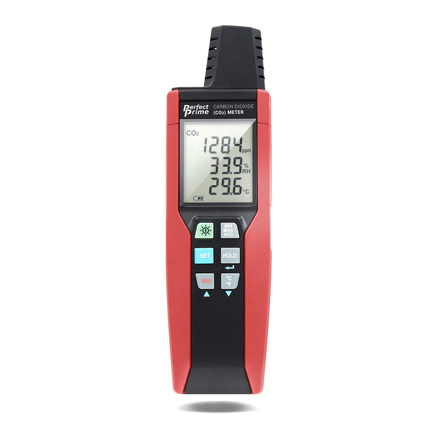
5. SYMBOL DEFINITION & BUTTON LOCATION : Battery condition indicator : Minimum indicator : Maximum indicator : Short-term exposure limit indicator : Time weighted average indicator : Setup option indicator : Auto power o enabled indicator : Recording data logger indicator : Memory full indicator : CO2 reading : Relative Humidity/Temperature reading... - Page 8 5. SYMBOL DEFINITION & BUTTON LOCATION CARBON DIOXIDE METER CO2 Sensor REC Button Display Screen °C/°F Button Power and Back Light Button Calibration inlet MAX MIN AVG Button USB Interface SETUP Button Tilt Stand DATA HOLD Button Battery Compartment...
-
Page 9: Power On/Off And Back-Light Button
6. BUTTON INSTRUCTIONS 6.1 Power ON/OFF and Back-Light Button: Press the button to turn on the meter. Press and hold the button for 3 seconds to turn o . Press to turn on the LCD backlight. This makes it easier to read in dark environment. -
Page 10: Max/Min/Avg Button
6. BUTTON INSTRUCTIONS 6.4 MAX/MIN/AVG Button: Under this mode, the unit simultaneously monitors and stores the minimum, maximum and average value in the memory. The unit will keep updating/refreshing the data. To start: Press button, symbol lights up on LCD, the reading shows the minimum data. -
Page 11: Setup Button
6. BUTTON INSTRUCTIONS 6.5 SETUP Button: Press the button to enter setup options. Press again to exit setup mode at anytime. Note: When the meter is connecting with PC, setup options cannot be entered. 6.6 °C / °F Button : Press to select the desired unit for temperature. -
Page 12: Operating Instructions
7. OPERATING INSTRUCTIONS Do not hold the meter close to faces in order to avoid exhalation Note: a ects reading (CO2). 7.1 Setup Options: Press the button to enter setup options. Press it again to exit anytime. ▲/ ▼button to adjust parameters or move setting Using the items. -
Page 13: Menu Description
7. OPERATING INSTRUCTIONS Fig.8 Set system clock. 7.3 Menu Description: 7.3.1 Setting interval time for data storing: ▲/ ▼button to increase / decrease minute Press the value. Press the button. ▲/ ▼button to increase / decrease second Press the value. Press the button to set interval. -
Page 14: Set Altitude Compensation
7. OPERATING INSTRUCTIONS ▲/ ▼button to increase / decrease Press the temperature value. Press the button. ▲/ ▼button to increase / decrease CO2 value. Press the Press the button to set all o set. Note: The o set to compensate for probe errors range: ±10%RH、 ±5°C or ±9°F、... -
Page 15: Set Auto Power O Time
7. OPERATING INSTRUCTIONS When setting on mode, press the button to set Hi and Lo limit. (CO2 alarm setting see Fig.11 and Fig.12) Fig. 9 Fig. 10 Fig. 11 Fig. 12 Note: Fig.16 When the measuring values go beyond alarm point, the symbol will blink “... -
Page 16: Set System Clock
7. OPERATING INSTRUCTIONS 7.3.6 Set system clock: The clock for the unit is built-in so that the data logger function can also record the data and time along with the measurement value. Press the button to select year, date, or time. (See Fig.15) Fig. -
Page 17: Calibration Procedure
8. CALIBRATION PROCEDURE The CO2 span gas can be in the range of 0 - 2000 PPM, 2% accuracy, with balance air. Make sure the concentration of the calibration gas is within the range of each sensor. Do not use gas that could over-range the sensor. For better accuracy, it is recommended that you use a span gas value close to the gas concentration you expect to measure. - Page 18 8. CALIBRATION PROCEDURE Turn o the meter. Press the , then press button for 3 seconds. LCD indicator: - - - → → In 3 seconds, press to enter calibration mode. LCD line1 indicator: CO2 real time reading. ▲/ ▼button to increase LCD line2 symbol blinking: Press the / decrease value.
-
Page 19: Power Reparation
9. POWER PREPARATION 9.1 Battery Replacement: When the battery voltage drops below proper operation range, the symbol will blink on the LCD display and the battery needs to be replaced. Before replacing the battery, power o the meter. Open the cover of the battery cabinet. Replace the old batteries with new 9V Alkaline battery (Carbon-zinc batteries are not recommended). -
Page 20: Maintenance
10. MAINTENANCE In order to ensure the accuracy of the NDIR CO2 Meter for a longer period of time you should calibrate it once a year. Clean the device and the window of the display with a clean, lint-free, antistatic and dry cleaning cloth. Do no use cleaning agents that contain carbon or benzenes, alcohol or anything similar to clean the product since these substances damage the surface of... -
Page 21: Se-512 Software
11. SE 512 SOFTWARE 11.1 The SE-512 package contains: Software CD disk. • Micro USB cable. • 11.2 System Required: Windows 7/ Windows 8/ Windows 10 11.3 Minimum Hardware Required: PC or laptop with CD-ROM drive. • At least 50 MB hard disk space available to install SE512. •... - Page 22 11. SE 512 SOFTWARE When the connection is successful, click “ Real Time | run ” or from main menu to start recording real time data and there will be a waveform on the Real Time Graph Window. Click “ Real Time | Stop ” or to stop recording.
- Page 23 11. SE 512 SOFTWARE 11.6 How to load the recorded data from the memory of Carbon Dioxide (CO2) Meter and save it to a file? Power on the Carbon Dioxide (CO2) Meter. Press the REC button of the meter to start recording data. After a while, press REC button again to stop recording data.
- Page 24 11. SE 512 SOFTWARE 11.7 Main Menu: Retrieve les from the disk. File | Open Save the active window (when the caption Save bar is highlighted) data to the disk. Print the data of the acitve window (graph Print or list). Select printer.
- Page 25 11. SE 512 SOFTWARE 11.8 DataLogger: When you have the Carbon Dioxide (CO2) Meter connceted to PC, select " DataLogger " from main menu or click Datalogger icon from tool bar to load recorded data from the meter and there will be a progress indicator to show the loading status.
- Page 26 11. SE 512 SOFTWARE It will generate the rst data set to graph on the right hand side. The user can also click at any other data set for graph. Graph: Tool Bar: Display or hide Statistic1. Display or hide Statistic2. Normal cursor.
- Page 27 11. SE 512 SOFTWARE When selected, the mouse cursor will become a " I " sign when moving to the graph, click on the graph to annotate. And all the text you make will exist with ppm. Select the channel. Graph Customization Change the Y axis extention To Undo the Zoom...
- Page 28 11. SE 512 SOFTWARE 11.9 Frequently Asked Question: 1. How to uninstall SE512? Uninstall SE512 by launching the Add/Remove Programs Answer: applet out of the Control Panel, highlighting the SE512, and clicking on the Add/Remove... push button, then it will remove the SE512 folder and les from your computer.
-
Page 29: Co2 Levels And Guidelines
12. CO2 LEVELS AND GUIDELINES NIOSH recommendations 250-350 ppm: normal outdoor ambient concentrations. 600 ppm: minimal air quality complaints. 600-1000 ppm: less clearly interpreted. 1000 ppm: indicates inadequate ventilation; complaints such as headaches, fatigue, and eye/throat irritation will be more widespread. 1000 ppm should be used as an upper limit for indoor levels. - Page 30 CUSTOMER SERVICE INQUIRIES Your emails are important to us so we strive to reply all hours. In exceptional cases, inquiries and emails within we may require more time to respond. Thank you for your understanding. For more information about our products and services, please send us an email: cs@perfectprime.com For B2B or project-based application, please send an email:...
- Page 31 HORMES LIMITED Retailer cs@perfectprime.com Email G/F UNIT 3, 61 GLENTHORNE ROAD, Address LONDON W6 0LJ UNITED KINGDOM +44 203 7695377 Telephone...
Need help?
Do you have a question about the CO2512 and is the answer not in the manual?
Questions and answers