Table of Contents
Advertisement
Quick Links
Advertisement
Table of Contents

Related Manuals for Perfect Prime 531


Summary of Contents for Perfect Prime 531
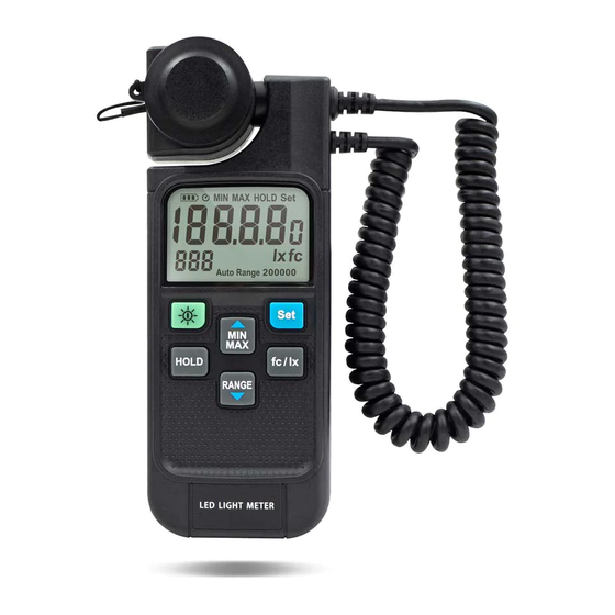
- Page 1 LIGHT METER Instruction Manual...
-
Page 2: Table Of Contents
CONTENTS 1. Safety Information ..............2 2. Introduction ................. 3 ............4 3. Precautions On Handling 4. Maintenance ................. 4 5. Specifications ............... 5 6. Symbol Definition And Button Location 6.1 LCD Display ..............6 6.2 Name Of Parts & Position .......... -
Page 3: Safety Information
1. SAFETY INFORMATION Read the following safety information carefully before attempting to operate or service the meter. Use the meter only as speci ed in this manual ; otherwise, the protection provided by the meter may be impaired. ENVIRONMENT CONDITIONS: Altitude up to 2000 meters •... -
Page 4: Introduction
2. INTRODUCTION Thank you for using our LED Light Meter. To ensure that you can get the most from it, we recommend that you read and follow the manual carefully before use. The Light Meter has been designed, manufactured, and delivered under strict quality control criteria by a factory certi ed. This meter has the following characteristic. -
Page 5: Precautions On Handling
3. PRECAUTIONS ON HANDLING 4. MAINTENANCE 3. PRECAUTIONS ON HANDLINGE Operating carefully, and do not drop the meter or hit it with a hard object. Avoid using the meter in a dirty, dusty, or salt-air area or where there are corrosive gases. -
Page 6: Specifications
5. SPECIFICATIONS 0.0 to 199.9/1999/19990/199900 lx Measuring range: 0.00 to 19.99/199.9/1999/19990 fc Automatic or manual selection of range 0.1 lx, 0.01 fc Resolution: ±3% rdg ±5 dgts (Standard A light source) Accuracy: 8% other visible light source 10° ± 1% 30°... -
Page 7: Symbol Definition And Button Location
6. SYMBOL DEFINITION AND BUTTON LOCATION 6.1 LCD Display: Minimum value indicator Maximum value indicator Autopower Value hold o indicator indicator Battery Set light source capacity mode indicator indicator Illumination value Light source Illumination correction value Unit choice indicator indicator Range indicator... -
Page 8: Name Of Parts & Position
6. SYMBOL DEFINITION AND BUTTON LOCATION 6.2 Name of Parts & Position * Operation: Press the power button to turn on the power. Notice that covering the light-detecting surface with the cap. “CAP-” will auto-appear on the LCD display. After “CAL-” appears, the meter enters the automatic zero adjustment. - Page 9 6. SYMBOL DEFINITION AND BUTTON LOCATION Note: If “ERR1” appears, check the cap to make sure it is on properly. 1 Lens Protecting Cover : This is used to protect the photo lance from scratching and create complete dark environment for the meter to perform dark current calibration.
- Page 10 6. SYMBOL DEFINITION AND BUTTON LOCATION Or it may be detached from the • unit to t the measuring requirement. LCD display: 6 1/2" large size back light LCD display. Power button: Push this button to turn on the meter. Push and hold this button for 3 seconds to turn it o .
- Page 11 6. SYMBOL DEFINITION AND BUTTON LOCATION HOLD button: The user may hold the present reading and keep it on the LCD display by pressing the button. To release the data held operation, user may press the button again. Max Min button: Push this button to set the meter working under MAX/MIN mode.
- Page 12 6. SYMBOL DEFINITION AND BUTTON LOCATION Set button: button, and use ▲and ▼to select a preset correction Press setting from L0 to L8. According to the lighting source, the user should set the appropriate preset correction for the accurate measuring result. The user can set his correction factor if a high precision light meter with “...
-
Page 13: Characteristics Of Sensor Spectrum Response
7. CHARACTERISTICS OF SENSOR SPECTRUM RESPONSE P.12... - Page 14 CUSTOMER SERVICE INQUIRIES Your emails are important to us so we strive to reply all hours. In exceptional cases, inquiries and emails within we may require more time to respond. Thank you for your understanding. For more information about our products and services, please send us an email: cs@perfectprime.com For B2B or project-based application, please send an email:...
- Page 15 Tyche Smart Limited Retailer Email cs@perfectprime.com 2nd Floor, 107 Charterhouse Street, EC1M 6HW, London, Address England UNITED KINGDOM +44 203 7695377 Telephone...
Need help?
Do you have a question about the 531 and is the answer not in the manual?
Questions and answers