
Related Manuals for Tektronix 1L30


Summary of Contents for Tektronix 1L30
- Page 1 , M illik a n W a y © P. O . Box 50 0 © B eaverton, O rego n 9 7 0 0 5 ® Phone 64 4-0161 © C ables: Tektronix 0 7 0 -0 5 2 0 -0 1...
- Page 2 CONTENTS Section 1 Characteristics Section 2 Operating Instructions Circuit Description Section 3 Section 4 Maintenance Performance Check Section 5 Calibration Section 6 Abbreviations and Symbols Parts Ordering Information Section 7 Electrical Parts List Mechanical Parts List Information Section 8 Mechanical Parts List Section 9 Diagrams Mechanical Parts List Illustrations...
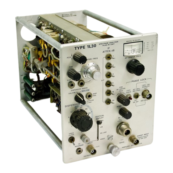
- Page 3 •**£g>v \ SWEEP INPUT ’ sawtooth stu c ro a = 50 V SERIAL ( f § ) - Ofi REAR PUTS ■PORTLAND. OREGON, U.S.A. .TEKTRONIX, K \C „ Fig. 1-1. Typa 1L30 Spectrum Analyzer Plug-In Unit. Type 1L30 ©...
- Page 4 The performance check procedure given in Section 5 of this manual provides a convenient method to check the 'A Tektronix Type 81 Plug-In Adapter must be used with 580-Series Operating requirements listed in this section. Oscilloscopes.
- Page 5 ; L f ! b < : ^ Characteristics— Type 1L30 ELECTRICAL CHARACTERISTICS (cont) Performance Requirement Supplem ental Inform ation Characteristic IF Attenuation 0 to 51 dB In 1 dB steps: 1, 2, 4, 8, 16 and 20 dB Range Accuracy ±...
- Page 6 .5 M Hz ± 1 0 % ( ± 5 0 kHz/cm) tails on environmental test procedures, including failure cri M Hz CAL MARKERS OUT teria, etc., may be obtained from Tektronix, Inc. Contact .2 M Hz ± 1 5 % ( ±...
- Page 7 (B) Effect of dis available. tortion on a cw signal. If the Type 1L30 Spectrum Analyzer is to be used with the Tektronix Type 541, 541 A, 543, 543A, 545 or 545A Oscillo Spectrum Analyzer— A device that displays a graph of...
- Page 8 Operating Instructions— Type 1L30 AIL POINTS MARKED — 1 5 0 V (DEC.) VERTICAL SIGNAL OUT CF V1223A /Type 545) 1 /2 6 D J 8 \ VT050V / + 320 FROM PIN 1 V154A (TIME-BASE GEN. A DIAG.) Fig. 2-2. Change as indicated on this partial schematic of the Vertical Amplifier.
- Page 9 O p eratin g Instructions— Type H 3 0 twice the IF. The spectrum analyzer is usually calibrated to Phase lock— The frequency synchronization of the local only one of these two responses. The other is called the oscillator with a stable reference frequency. image.
- Page 10 Operating Instructions-—Type 1L30 POS— Controls the ver IF ATTEN dB— Series of RF CENTER FREQ— Con tical position of the dis calibrated attenuation trol tunes the local os play. steps. cillator dial. Dial indicates the cen ter frequency of the dis...
- Page 11 C • ^ ! : ? _ ' • • = . j& j& i r-t' ' :V _* »w&i Operating Instructions— Type tL30 40 dB. In the LIN position, a signal display in the 0 position, the analyzer functions as amplitude is linear with a dynamic range a fixed tuned receiver.
- Page 12 VERTICAL DISPLAY Set the Sweep Voltage selector at the rear panel [see G A IN Fig. 2-4) Type 1L30 to the correct position (100 V or 150 V) Centered for the oscilloscope being used. Some Tektronix Type Oscillo FINE RF FREQ...
- Page 13 Operating instructions— 1L30 Type ment of the display baseline. This baseline vertical shift range of this control. This control will shift the IF center is the change in the output DC level of the phase lock-am frequency approximately - f or —...
- Page 14 DISPERSION, IF CENTER FREQ and the DISPER SION RANGE balance. These front panel adjustments must GENERAL OPERATING INFORMATION be recalibrated whenever the Type 1L30 is shifted to an other oscilloscope, to compensate for differences in sawtooth amplitudes and CRT deflection sensitivities.
- Page 15 O peratin g Instructions— Type H .30 with the sweep extending over the 10 centimeter width of DISPERSION 1 MHz the graticule. Front panel calibration is required if this VERTICAL DISPLAY SQ LAW requirement is not met. Proceed with the follow ing adjust IN I 1 MHz REF FREQ ments if front panel calibration is required.
- Page 16 Operating Instructions— Type 1L30 Fig. 2-7. Vertical display modes showing an amplitude modulated display. Video mode shows the modulation signal. Oscillator phase lock operation is established as follows: After phase lock operation has been set, the dispersion Tune the desired signal to the center of the screen with the may be reduced.
- Page 17 The frequency excursion of the frequency axis of the dis play is usually expressed as frequency per centimeter. The dispersion for the Type 1L30 is adjustable from lO M H z/c m to 1 kHz/cm in a 1, 2, 5 sequence with an added zero dis...
- Page 18 See S p e c tru m Sweep Time (in s) A nalyzer definitions. The resolution of the Type 1L30 Spectrum A na lyze r is optim ized for most settings of 1 he DISPERSION selector when the RESOLUTION! control is in ihe coupled position.
- Page 19 Type 1L30. for free run operation, however, there are applications, for example; at 0 dispersion, or when slaving the Type 1L30 to a recorder, that it may be desirable or necessary to trig Spectra of Amplitude Modulation ger the display.
- Page 20 - ( ------------- FREQUENCY Fig. 2-14. Formation of a spectrum. F is the fundamental or carrier frequency. Ft and F2 are the modulating frequencies. The amplitude modulated signal spectrum therefore fur nishes the following information: 1) Fundamental or car rier frequency, 2) modulation frequency or frequencies, 3) modulation -percentage, .4) sideband energy...
- Page 21 T«fr til f i * *rtt -, lYiVr^Vftii ^itirifaifl§l Operating Instructions— Type H 3 0 h' / . ■ ■ Narrow band FM. Note the resemblance to AM. f > : CARRIER 100 KHz/CM DISPERSION 2 GHz (C) Carrier almost at a null. (D )* Carrier at null.
- Page 22 IF feedthrough signals on a 100 M H z dispersion screen. 2. Signal images: The dial scales of the Type 1L30 Spec trum Analyzer are calibrated below' the frequency of the tunable first local oscillator. The response to an input sig...
- Page 23 For maximum accuracy, the signals should be refer enced and compared near the same location on the dis- These basic applications for the Type 1L30 Spectrum An , play. Tune each signal to the reference with the RF alyzer are a few examples of its use and are presented to CENTER FREQ control.
- Page 24 Operating Instructions— Type 1L30 reading). The frequency of an applied signal is measured as follows: 1. Check the calibration of the IF CENTER FREQ CAL ad justment as described previously. 2. Set both the IF CENTER FREQ controls and the FINE RF CENTER FREQ control to their midrange (000) position.
- Page 25 Frequency S tab ility the frequency modulated carrier. ? ■ The Type 1L30 may be used to measure both long and short term frequency instabilities, when the local oscillator is Frequency Deviation Measurement phase locked to a stable crystal-controlled reference fre...
- Page 26 ’ High Resolution Capabilities Figure 2-23 illustrates resolution capabilities of the Type 1L30. The DISPERSION is set to 1 kHz/cm and the RESO LUTION is uncoupled and turned fully counterclockwise. To -•I increase the apparent resolution turn the VIDEO FILTER switch O N .
- Page 27 5 = . ¥ ' ■ (A) Signal modulated by a 1 kHz signal. VIDEO FILTER (B) Same signal as A, VIDEO FILTER ON. OFF. LIN mode. (Cl Amplitude modulated signal. 2 kHz sidebands. (D) Same signal as C. VIDEO FILTER ON. Fig.
- Page 28 Basic Description volt regulated supply. The heater supply line to V41 includes A functional block diagram of the Type 1L30 is shown in a shunt dropping resistor, R46, to reduce the voltage to 6 Fig. 3-1 and in the Diagrams section of this manual.
- Page 29 MIXER 150-250 MHz 935 MHz - 10.5 GHz 150-250 MHz WIDE BAND 280 MHz 1 MHz IMPULSE LOW PASS BAND PASS AMPLIFIER REFERENCE GENERATOR FILTER FILTER MIXER FREQUENCY RF AMPLITUDE COMPARATOR L.O. SAMPLING I DISPERSION | i - ---- ----------- 1 I i i L.O.
- Page 30 ^ r V i . i - i ^ : 7 i^ ^ ifi^ n -^ ir r > ■ i Circuit Description— Type 1L30 The phase detector samples the instantaneous RF voltage swings negative, D821 turns on, pulling the transistor base generated by the tunable local oscillator at a rate deter...
- Page 31 Circuit Description— Type 1L30 Input strobe pulses Fig. 3-3. Simplified phase detector circuit. are of equal and opposite polarity, the resultant voltage The sawtooth voltage from the oscilloscope is connected will approximately equal the instantaneous (or sampled) to the analyzer SWEEP INPUT connector by an external oscillator voltage.
- Page 32 • i ' ~1 : •-H i*' ■ '•*••’ * •■ *& *■ Circuit Description— Type 1L30 •!■ ■ ■ Sawtooth Input Fig. 3-4. Block diagram of the sweeper circuit. The generator, or source, is in series with the output wind...
- Page 33 D387 isolate the narrow band dis average DC level of the output signal to Q240. This allows criminator tuned circuit when the Type 1L30 is operating in the IF center frequency to be shifted without affecting the the M H z /C M dispersion range.
- Page 34 Circuit Description— Type 1L30 plished by the RF amplitude comparator circuit, Q290 and because of the low Q in the collector circuit due to R134 Q280. The RF output signal is detected by diode D361 and and circuit loading, the overall effect of both adjustments applied through diode D362 to the base, of Q280.
- Page 35 .Circuit Description— Type 1L30 Fig. 3-8. Crystal filter, equivalent circuit and impedance response Fig. 3*7. Crystal variable resolution filter. curves. in series between the input and the parallel resonant cir The bandwidth of the filter network is a function of the cuit L508-C508.
- Page 36 Circuit Description— Type 1L30 response is very narrow, so the display resolution is in creased as the diode forward bias increases. SW550, the RESOLUTION selector, can be coupled to the .DISPERSION selector and when so coupled, provides normal resolution for each position of the DISPERSION selector pro...
- Page 37 R665 develops sufficient volt circuits in the Type 1L30. Reference voltage for Q710 is ■ I age across D665 to turn this diode on, and the two diodes set by the voltage divider R710-R711, between the regulated now operate in series to extend the range of the Log cir...
- Page 38 Introduction This section of the manual pertains to the maintenance The life of potentiometers and selector switches is in and troubleshooting of the Type 1L30. The first portion of creased if these devices are properly lubricated. Use a the section describes some general preventive measures to cleaning type lubricant (such as Cramoline) on shaft bush...
- Page 39 . W e recommend when -possible that The instrument contains a number o f stable metal-film the entire unit be returned to a Tektronix Repair resistors identified by their gray background color and color Center.
- Page 40 A tan background in dicates a negative supply. Table 4-2 shows the wiring color code for the power supply voltages used in the Type 1L30. TABLE 4 -2 W irin g C olor-C ode Back...
- Page 41 3. Release the rear panel by removing all screws except 4. Using special tool Tektronix Part No. 003-0397-00 (see the two holding the interconnecting plug, the two holding Fig. 4-6) unscrew the spanner nut, then gently lift out the the sawtooth voltage selector switch and the screws hold...
- Page 42 W i.1 ^^: k v M a in te n a n c e — Type 1L30 Removing and Remounting the Honeycom b Assembly 1. Loosen the front set-screw on the coupler to the DIS...
- Page 43 Maintenance— Type 1L30 Fig. 4-8. One method of removing the IF chassis for troubleshooting. ;‘it Fig. 4-10. Phcss lock assembly removed and ready to troubleshoot. 6. Slide the assembly ta c k and out o f the " U " shaped cover.
- Page 44 ■ . - visable to use solder containing about 3% silver for the main (no connection) tenance of Tektronix instruments. This solder may be pur ‘ H’ Tan-brn-gm ( — 150 V) chased directly from Tektronix, Inc; order by Part Number 251-0514-00.
- Page 45 Attempt to isolate trouble to one circuit through operational Stud and visual checks. Verify that the trouble is actually a mal function within the Type 1L30 and not improper control setting or malfunctioning associated equipment. Note the effect the controls have on the trouble symptoms. Normal...
- Page 46 i-iw i Jvieei iti* Maintenance— Type :■ : .10 ode with the typical voltages listed on the diagram will help resistance ratios of tunnel diodes or mixer diodes. isolate faulty, diodes. Forward-to-back resistance ratios on some diodes can be checked by referring to the schematic Some Trouble Symptoms and pulling appropriate transistors and square pin connectors to remove low resistance loops around the diode.
- Page 47 ,'-,'v',vfif'i V lYSii tiV t«ii> frfrVi ’ a I'^YSriSiTiVif-i jl;ni»''Ji*ii» lifliiiM lfiifurtiitTii' jliT f*' . i.i»rT »• fC u & & * ■ ! Maintenance— Type 1L30 v „ . „ Fig. 4-14. Phase Lock and Recorder Detector circuit boards.
- Page 48 . L^i £ y.n M ain ten an ce— Type 1L30 Fig. 4-15. Honeycomb assembly drcui} component layout. a n d 4 - n...
- Page 49 DC to 30 MHz. Tektronix Type 540-series Oscillo 21. Patch cord with BNC to banana plug tips: Tektronix scope with Type 1A1 Plug-In Unit and Tektronix P6010 (1 0 X ) Part No. 012-0091-00. and P6011 ( I X ) test probes.
- Page 50 50 f' termination to the RF INPUT connector. control or the IF CENTER FREQ control may be used to (Signal input to. the Type 1L30 should be less than —30 dBm.) align the prime markers to the graticule divisions. The RESO...
- Page 51 Return the VERTICAL DISPLAY switch to the LIN posi e. Check the resolution bandwidth response of the Type tion. 1L30 to the 200 M H z signal at the — 6dB points. To check TABLE 5-1 Supplem entary DISPERSION...
- Page 52 Performance Check— Type 1L30 the vertical location o f the —6d B points, switch in an ad c. Change the VERTICAL DISPLAY switch to the LIN posi ditional 6 dB of IF ATTEN and note the position of the top tion (Sweep rate 20 ms/cm or slower).
- Page 53 10 dB below 1 mV, through a 2 X Attenuator (6 dB), a must be used. Tens and Units Step Attenuator and a 1 0 X Attenuator (20 dB) to the Type 1L30 RF INPUT connector. (Fig. 5-5.) b. Apply 10 ns and 1 /.is markers from the Time-Mark...
- Page 54 4 cm, ± 0 . 5 mm (.1 dB/dB). TABLE 5 -3 c 3. Switch the Type 1L30 IF ATTEN switch to OFF posi Spectrum A n a ly ze r RF G en erato r Attenuatjor tion, then check the remaining IF ATTEN switch steps...
- Page 55 Adjust the MIXER PEAKING for maximum signal Check the input signal frequency. Must equal or be less amplitude. than 16 Hz. Remove the signal to the Type 1L30 Video IN PUT and the test oscilloscope. Decrease the DISPERSION to 1 kHz/cm, keeping the phase locked signal on screen by adjusting the IF CENTER FREQ conlrols.
- Page 56 .Adjust the MIXER PEAKING control for optimum sig ator output attenuator control for an on-screen display; then nal amplitude then adjust the Type 1L30.G A IN control and re-adjust the MIXER PEAKING control and sweep rale for the generator output for a signal amplitude of 5 cm. Re...
- Page 57 Performance Check— Type 1L30 NOTE c. Set the DISPERSION RANGE to kH z/C M , the DISPER SION to 500 kHz/cm and the RESOLUTION control fully Cable losses for frequencies of 10 G Hz and higher clockwise (100 kHz). become significant and must be added for correct sensitivity measurements.
- Page 58 ± 1 % . Hewlett-Packard Type 355D and Type 355C Step Recommended Equipment Attenuators. The equipment used to calibrate the Type 1L30 is listed 8. (Optional.) Swept-Frequency Generator; frequency range • in two groups. Group one includes basic equipment re...
- Page 59 Fig. 6-1 A. Test equipment required for calibration. ©...
- Page 60 .Calibration— Type 1130...
- Page 61 Frequency range 925 M Hz to 10,500 MHz, ac P6041 probe; Part No. 010-0164-00. curacy ± 1 % ; output power — 100 dBm to — 30 dBm; output 21. Two (2) BNC, coaxial cables, 50 Q. Tektronix Part No. impedance 50 fi. Suggested equipment: 012-0057-01.
- Page 62 Disp Cal R208 for dispersion accuracy and C358 for & REF FREQ position. Check for phase lock beat signals dispersion linearity with the Type 1L30 Dispersion through the frequency range of the RF CENTER FRE set to 10 M H z/C M .
- Page 63 SW201 (on the rear panel) to the appropriate position. Con nect the coaxial cable from J109 to J120. Apply an nect the Type 1L30 Spectrum Analyzer through a flexible amplitude calibrated signal that is approximately extension (Part No. 012-0038-00) to the J ll connector of the —...
- Page 64 Type b. Connect the probe of a DC coupled test oscilloscope Position a free to chassis ground on the Type 1L30. Establish 0 V reference trace to the level on the test oscilloscope, then connect the probe to line of the g pin P of the square pin connector for the honeycomb as...
- Page 65 Dispersion accuracy and the display linearity for the Type in the display. To avoid confusion, tune the RF 1L30 is a function of the RF output amplitude, circuit con center frequency w ith the RF CENTER FREQ and stants, etc. DISP CAL adjustment R208 primarily affects the...
- Page 66 ;^ g fX ■ . . ■ -y.' , Calibration-— Type 1130 b. Center the IF CENTER FREQ controls. This marker This marker c. Check the dispersion accuracy for the M H z/C M set on graticule x cm on 9ral 'cu'e ting of the DISPERSION selector as listed in Table 6-1.
- Page 67 < Calibration— -Type 1L30 •"3 Fig. 6-7. Equipment setup to adjust the !F amplifier reponse and the resoluticn badwidth (steps 4 and 5 ). Type 1L30 b. Apply a 200 MHz signal from the Time-Mark Gen erator (2nd harmonic of the 10 ns marker) through a 40 dB Position a free running attenuator (two 1 0 X attenuators) to either RF INPUT con...
- Page 68 :.li6 ^ S K i e M j W s i L -J Calibration-— -Typo 1130 • tr t" Fig. 6-8. Location of the IF amplifier peaking adjustments. b. Apply the 10 ns signal from the Time-Mark Generator through a 40 dB attenuator to the RF INPUT connector. Set DISPERSION to 50kH z/cm and the RESOLUTION control £...
- Page 69 Calibration— Type 1L30 2. Adjust L624 for op timum signal ampli tude with rounded 1. Adjust R543 for a shoulders this resolution bandwidth point. > TOO kHi with RESOLUTION control fu ll/ clockwise and a p p r o x i m a t e...
- Page 70 Time/Cm 10 ms NOTE Triggering Adjusted for a free run ning sweep An altern a te method to a p p ly frequency markers Horizontal Position Centered trace to the Type 1L30 is as follow s: 6-13 ©...
- Page 71 C alibration— Type 1L30 • 1 ■ $ 1 m arker/2 centimeter (Checking 500 kHz/CM disper sion.) Center marker is 200 MHz feedthrough. Fig. 6-14. Location of kHz/CM dispersion adjustments. ( 1 ) A p p ly a calib rated...
- Page 72 T connector to the EXT FREQ IN connector. Con Time/Cm 10 ms nect the test oscilloscope to the T connector, so that the input signal amplitude to the Type 1L30 can be monitored. Triggering Adjusted for a free running sweep d.
- Page 73 ■ ''*fi i ifrriitrt i ti^Wii'F''" CctUbraHon— Yyp^ 1130 ^ i^ .‘ iyc? < ffW (A) Circuit free running. Fig. 6-17. Phase-lock circuit adjustments. lock beats (see Fig. 6-19) as the RF CENTER FREQ control is rotated. e. Increase the generator output signal level to 5 volts. Check for phase lock beats.
- Page 74 2 X Attenuator (6 dB), a Tens and Units Step Attenuator and a 1 0 X Attenuator VERTICAL DISPLAY (20 dB) to the Type 1L30 RF INPUT connector. Switches off IF ATTEN Centered FINE RF CENTER FREQ c.
- Page 75 Step Spectrum A nayzer Attenuators Signal Am plitude IF ATTEN c. Adjust the Type 1L30 G A IN control a n d /o r the Signal Limit (.1 d B /d B ) Switch on Units Tens Generator Variable Attenuator for a signal amplitude of 6 cm (full screen display).
- Page 76 Calibration— ‘Type , V0 c. W ith the VERTICAL DISPLAY switch in the LIN posi tion and 200 M H z signal ap p lied to the RF INPUT connector, adjust the G A IN control a n d /o r the Signal G enerator output for a display am plitude of 6 cm, .
- Page 77 DISPERSION-COUPLED 10 MHz RESOLUTION c. Turn the Type 1L30 G A IN control fully clockwise. A d VIDEO FILTER just the signal generator output control for a signal am pli tude of 4 cm on the plug-in oscilloscope, then adjust the test...
- Page 78 NOTE h. Increase the frequency of the signal generator until the signal amplitude on the plug-in oscilloscope decreases The Type 1L30 Unit must be plugged directly into to 2.8 cm. Maintain a constant 4 cm signal amplitude on the oscilloscope vertical com partm ent for the high the monitor oscilloscope.
- Page 79 Signal source must supply a very stable 2 0 0 M H z IF CENTER FREQ signal to accu rately measure incidental FM and Midrange (000) the Type 1L30 must b e on a vib ra tio n -free p la t FINE Centered form .
- Page 80 C alib ratio n — Type H 3 0 g. Change the DISPERSION to 100 kHz/cm. Shift the IF feedthrough signal off screen by tuning the IF CENTER FREQ control. Adjust the RF CENTER FREQ control to center a converted or tunable signal display on screen. Adjust the MIXER PEAKING for maximum signal amplitude.
- Page 81 W ide Band IF Amplifier FINE RF CENTER FREQ Centered The Type 1L30 response flatness and sensitivity is depend INT 1 MHz REF FREQ ent on the combined response of the wide band amplifier, the band pass filter, the low pass filters and the RF mixer.
- Page 82 MIXER PEAKING control for maximum decrease in the vertical displacement of the plug-in oscillo signal amplitude, then adjust the Signal Generator output scope trace. control and the Type 1L30 G A IN control for a signal am- © 6-25...
- Page 83 Calibration— Type 1L30 TABLE 6 - 4 plitude of 5 cm. This must be repeated for each Signal Gen erator frequency change. A p p lied Signal RF Center Frequency (4) Check the display flatness over the dispersion window G en erato r Frequency...
- Page 84 If an external atte n u ato r is used, it must have fla t Midrange G A IN high frequency characteristics: Use Tektronix 2 0 VERTICAL DISPLAY dB A ttenu ato r Part N o . 0 1 1 -0 0 8 6 -0 0 , or 4 0 dB...
- Page 85 ■ '* Calibration— Type 1L30 ator output attenuator control for an on-screen display, then adjust the MIXER PEAKING control and the sweep rate selector for optimum signal amplitude. (Sweep rate approxi mately 20 ms/cm or slower.) Calibrate the Signal Generator output signal amplitude,...
- Page 86 Horizontal Position 19. Check Amplitude of Spurious Signals from Internal Sources a. Equipment setup is shown in Fig; 6-29. b. Install the Type 1L30 into the plug-in oscilloscope verti cal compartment. Connect a 50 0 termination on the RF INPUT connector.
- Page 87 Replace the back panel of the DC to 3900 MHz, Dual-Trace display, sensitivity 2 mV/cm. Type 1L30 and install 2 to 3 screws to hold the panel in Tektronix Type 661/4S2A/5T3. place. (This reduces the possibility of short circuits.) Fig.
- Page 88 Calibration— Type 1L30 7. Adjust the power output probe penetration and orien tation for approximately 1 V peak to peak into 50 f2 for both output signals as indicated on the dual trace sampling os cilloscope system. Tighten the probe set screws at this point.
- Page 89 vii'»feii^l’ ? ^t^'sftr^ii l ^r^l^i'niif'T1 ‘r^'if ‘ ‘ I'lftliijl"' iIi<~r’: I*--'' C alibration--Type IL30 fa & i - V . $ ■ Turning the Varactor assembly clockwise will reduce the * c. Push forw a rd on the dial tape, to free the tape from oscillator frequency.
- Page 90 Connect one oscillator output cable to the mixer in This completes the oscillator test and calibration. Install the Type 1L30, and the other output cable to the phase lock the oscillator assembly using the reverse procedure used to (J855).
- Page 91 ABBREVIATIONS A N D SYMBOLS A o r omp inductance amperes AC or ac lambda—wavelength alternating current » large compored with audio frequency < less than oloha— common-base curient a m plificatio n factor low frequency am plitude modulation length or long approxim ately equal lo low voltage amplification...
- Page 92 Type 1L30 SECTION 7 ELECTRICAL PARTS LIST Values are fixed unless marked Variable. S /N Range Tektronix Ckt. N o . ________ Part N o ._____________ Description Capacitors Tolerance ± :2 0 % unless otherwise indicated. C811 C83l C.861 1.5-9.1 pF...
- Page 93 • X ..X Electrical Parts List— Type 1L30 Capacitors (C on t) Tektronix Ckt. N o. Part N o . Description S / N Range C274 281-0605-00 200 pF 500 V C293 283-0010-00 0.05 5 0 V f t ?
- Page 94 Electrical Part* List— Type 11.30 Capacitors (C o nt) Tektronix Range Description S /N Part N o . Ckt. No. 500 V 281-0550-00 120 pF C447 500 V 281-0511-00 22 pF C450 500 V 283-0001 -00 0.005 ju,F C453 500 V...
- Page 95 ;^LW .VA^vjL6^2j •--rii^'V‘L'^lrL“^ ' ll^ ^ il i T^Jl4“i-y j^ :A i Electrical Parts List— Type 1L30 Capacitors (Cont) Tektronix Ckt. N o . Part N o. Description S /N Range C859 283-0065-01 0.001 100 V 283-0059-00 C876 25 V...
- Page 96 -~-^ -^'^•./■ y^rt^^iiiii-r'i'M -' I' ri* i ' Electrical Parts List— Type H 3 0 Connectors Tektronix Description S /N Range Ckt. No. Part No. Adapter *103-0057-00 J801 J941 Coaxial 131-0372-00 J100 Coaxial 131-0372-00 J109 Coaxial 131-0372-00 J120 Coaxial 131-0372-00...
- Page 97 Electrical Parts List— Type 1L30 inductors (C onf) Tektronix Ckt. N o . Part N o ._______________________ Description S /N Range LI 34 *114-0205-00 54-66 nH Core 276-0506-00 LI 44 *114-0206-00 234-286 nH Core 276-0^06-00 LI 47 *114-0205-00 54-66 nH...
- Page 98 Electrical Fan's List— Type 1L30 Transistors Tektronix Description S /N Range Part N o . Ckt. No. 151-0180-00 Silicon 40235(RCA) 101-559 Q120 *151-0230-00 Silicon Replaceable by 40235 (RCA) 560-up Q 120 151-0180-00 Silicon 40235(RCA] 100-559 Q130 *151-0230-00 Silicon Replaceable by 40235 (RCA)
- Page 99 Electrical Parts List— Type 1L30 Resistors (ConfJ Tektronix Ckt. N o. Part N o. Description S / N Range R123 315-0101-00 ioo a V* w R124 315-0471-00 470 n v4 w X560-up R128 315-0332-00 3.3 kn y4 w 315-0221-00 R130 220 n y»...
- Page 100 D ectrical Parts List— Type 1L30 :• Resistors (C o n i) Tektronix S /N Range Description Part N o . Ckt. N o. 49.9 n y .w Prec 321-0068-00 R223 ■ 30.1 n y .w Prec 321-0047-00 R224 Prec...
- Page 101 Electrical Parts List— Type 1L30 Resistors (Cont) Tektronix Ckt. N o . Part N o . Description S / N Range • .< '•$ 7.5 Ma y2 w R271 301-0755-00 2 ka R274 .311-0590-00 y4 w R276 322-0469-00 750 kQ...
- Page 102 ’ ■'j-v^t?WnA~rr- -fry- Z 8 & k i'- '£UAiiuui&&£ Electrical Parts List— Type 1L20 Resistors (Cont) E V , Tektronix Range Description Part N o , Ckt. No. 1/10 W 317-0151-00 50 a R502 315-0470-00 47 a R514 315-0242-00 2.4 ka R516 Vi w .
- Page 103 Electrical Parts List— Type 1L30 Resistors (C ont) Tektronix Ckt. N o . Part N o. Description S /N Range 315-0124-00 *5°/ 630-up 6 6 8 ^ /O R669 323-0071-00 53.6 n Prec 5.1 kn R671 301-0512-00 100-629...
- Page 104 Electrical Parts List— Type 1L30 • <- Resistors (C o n i Tektronix S / N R ange Part N o . Description Ckt. No. y .w X44Q-up R877 321-1485-00 . 1.11 .-MG Prec 316-0126-00 12 Mn 100-439 R886 432 ka...
- Page 105 Electrical Parts List— Type 1L30 Transformers (ConfJ Tektronix Ckt. No. Part N o ._______ Description S / N Range T424 *120-0425-00 Toroid, 4 turns— 1 turn T434 *120-0426-00 Toroid, 7 turns— 2 turns T454 120-0356-00 3.45 MHz 1464 120-0356-00 3.45 M Hz...
- Page 106 Mechanical Parts List— Type 1L30 ■i ■ INDEX OF MECHANICAL PARTS LIST ILLUSTRATIONS (Located behind diagrams) FIG. 1 FRONT FIG. 2 REAR & CHASSIS FIG. 3 IF CHASSIS FIG. 4 W ID E BAND FILTER & PHASELOCK ASSEMBLY FIG. 5 STANDARD ACCESSORIES...
- Page 107 & i 'Vi.v -•■ ■ ' FIG . 1 FRONT Fig. & S e ria l/M o d e l N o . Index Tektronix Description Disc N o. Part N o . 1 2 3 4 5 PANEL, front...
- Page 108 M echanical Parts List— Type 1L30 FIG. 1 FRONT (cont) Fig. & Index Tektronix S e ria l/M o d e l N o . Description N o . Part N o .__________ Eff_____________ Disc_______y 1-12 262-0763-00 SW ITCH, wired— COUPLED RESOLUTION— DISPERSION...
- Page 109 „;'■ * '~ <s^ jf6 : ^ .« a-^jlyyy . . ^ , i ^ i « j v i » W . ' - ~ !••'■•y^'^w. ^■.a^!i.-,.Vj-'.fV-;. 1L30 Mechanical Parts List— Type FIG. 1 FRONT (confj Ficj. & S e tia l/M o d e l N o .
- Page 110 Mechanical Paris List— 'Type 1 L30 FIG. 1 FRONT (confj Fig. & Tektronix S e ria l/M o d e ! N o. Index Description N o. Part No. Disc 1 2 3 386-1026-00 PLATE, sub-panel, front 1-40 1 0 0...
- Page 111 Mechanical Parts List— Type 1L30 PIG. 1 FRONT (cont) Fig. & Tektronix S e ria l/M o d e l N o . index Description Disc N o . Part N o . ADAPTER, connector 1-55 103-0057-00 CABLE HARNESS, phase lock...
- Page 112 Mechanical Parts List— Type 1L3Q FIG. 2 REAR & CHASSIS Fig. & Index Tektronix S e ria l/M o d e l N o . Description N o . Part N o . Disc 5_________________________________________________ 386-1025-00 PLATE, rear 131-0017-00 CONNECTOR, 16 contact, male...
- Page 113 Mechanical Parts List— Type 1L30 FIG. 2 REAR & CHASSIS (cont Fig. & In d ex Tektronix S e ria l/M o d e l N o . Description Part N o . Disc N o . 3 4 5 _____...
- Page 114 Mechanical Paris List— Type 1L30 FiG . 2 REAR & CHASSIS (confj Fig. & Index Tektronix S e ria l/M o d e l N o . Description N o . Part N o . Disc 3 4 5_______________ _______...
- Page 115 Mechanical — Type 1130 Parts List FIG. 3 IF CHASSIS Fig. & S e ria i/M o d e l N o. Tektronix Index Description Disc Part N o . N o . 1 2 3 4 5 r‘ ;...
- Page 116 Mechanical Parts List— Type 1L3Q FIG. 3 IF CHASSIS (cont) Fig. & S e ria l/M o d e l Index Tektronix Description Disc N o. Part N o. COIL 3-22 mounting hardware: (not included w/coil) ROD, spacer, % x % inch...
- Page 117 M echanical Parts List lL 3 o FIG . 4 W ID E BA ND FILTER & PHASE LOCK ASSEMBLY Fig. & Index Tektronix S e ria l/M o d e l N o . Description N o . Part N o .
- Page 118 • ~ r ~ i i - 'ri * T V ' w ' t t‘'tv i f t i T ? i Mechanical Paris List— Type 1L30 FIG. 4 W ID E BAND FILTER & PHASE LOCK ASSEMBLY (cont} Fig.
- Page 119 1 2 3 4 5 134-0052-00 PLUG, red 012-0091-00 CORD, patch, BNC to banana, red, 18 inches long 134-0076-00 PLUG, protector 070-0520-01 MANUAL, instruction (not shown) © TYPE 1L30 SPECTRUM ANALYZER 9 - 2 9 / 9 - 3 0 sswwssrfe-...
- Page 120 £ \ib i SYSTEM BLOCK DIAGRAM T Y P E I L 3 0 S P E C T R U M A N A L Y Z E R 9 -1 /9 -2...
- Page 121 S^*i&**, ■I F OUT TO 1 5 0 - 2 3 0 M Hx BAND PASS FILTER < l > TO LOCK. CHECK. SWITCH <§> 12.67 AND P H A S E LOCK. BLO CK. D IA G R A M T Y P E IL S O S P E C T R U M...
- Page 122 (M H z ) & R E F E R E N C E DIA GRAM S : SE E P A R T S L IS T F O P P H A SE LOCK. C IR C U IT S E M IC O N D U C T O R T Y P E S §...
- Page 123 Ms&im SEE PARTS ItST FOR EARLIER VALUES AND SERIAL NUMBER RANGES OF PARTS MARKED WITH BLUE OUTLINE £ n<o7 PHASE LOCK CIRCUIT T Y P E . I L 3 0 S P E C T R U M A N A L Y Z E R <...
- Page 124 ■^mm mkt&aA E*» A M PLIFIER AMPLIFIER S E E P A R T S U S T F O R SEMICONDUCTOR T Y P E S •* d e n o t e s s e l e c t e d l o s s y c o a x <*...
- Page 125 ffeiifr-I,,."- ■ ■ r,v , ..i.^ J^aB4^£d^> ..ft^U m ,^-,,- A & & > . iw&u>*» .2 * ■ * , RZC6 +iov 0 2 - 0 ;2J0 CENTER - © • ^ ‘i ♦ ^4..99K + 350''\| „.. > «5 i “•...
- Page 126 -----. . . ^ ------------ ^aslrtwJiA^rt^n. ^£2iUtoUitiSJSMto^ AT T E N > BWV69 SWISS iwn 4 SWIT9 W lbA J >W \S4 I------- L .? -P F — i I-------1 » ■ *> I-------1 - - Q D -------1 i— s >...
- Page 128 k^aaaaigliiSiig^^ ___ j^A*«»»«ffift^W^ T s > fe SEC f A*TS U5T CO# EAKUER VALUES AND Sf*SAl NUMBER CANOES O f PA6TS MARKED it&fc WITH ELUE OUTUNE. T Y P E 1 L 3 0 S P E C T R U M A N A L Y Z E R VARIABLE RESOLUTION CIRCUITS...
- Page 129 uJ.^---- ■ 1 . IV /D IV ! ' . i R E F E R E N C E DIAGRAM S < ^ > S E C T I O N <£ > PHA.SE LOCK c i r c u i t <...
Need help?
Do you have a question about the 1L30 and is the answer not in the manual?
Questions and answers