Chapters
Table of Contents

Related Manuals for Tektronix 1L40


Summary of Contents for Tektronix 1L40
- Page 1 IV IA IN I U A L Serial N u m h e f/ ^ * - ‘ 1L40 TYPE L e ^ h i SPECTRUM ANALYZER T e k tro n ix , Inc. S.W. M illik a n W a y •...
- Page 2 WARRANTY All Tektronix instruments are warranted against defective materials and workman ship for one year. Tektronix transformers, manufactured in our plant, are warranted for the life of the instrument. «-r Any questions with respect to the war ranty mentioned above should be taken up with your Tektronix Field Engineer.
-
Page 3: Table Of Contents
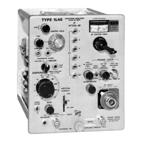
Abbreviations and symbols used in this manual are based on or taken directly from IEEE Stand ard 260 ‘‘Standard Symbols for Units", MIL- STD-12B and other standards of the electronics industry. Change information, if any, is located at the rear of this manual. Type 1L40... - Page 4 FREO MARKERS CHECK > £ $ * 5 7 ^ OISPERSI' RF INPUT SWEEP INPUT MWI0OTN K1ICTW > O N «» B MATE SERIAL PORTLAND. OREGON U S-A TEKTRONIX. INC Fig. 1-1. Type 1140 Spectrum A nalyzer Type 1L40 ®...
-
Page 5: Specification
< 3 0 0 Hz at local oscillator fundamen display Lock tal. 'A Tektronix Type 8 1 A Plug-In A dop ter must be used w ith 580 Series Oscilloscopes. Internal Phase Lock J The Type 1L40 is norm ally supplied w ith a coaxial mixer, Tektronix Internal Markers 1 MHz + 0.1% (INT REF FREQ control... -
Page 6: Table
MIXER PEAKING adjusting for optimum signal am plitude. ‘To be used w ith W aveguide M ixe r A dap ter Tektronix Part No. 1 1 9 -0 1 0 4 -0 0 and cable TNC, coaxial, Tektronix Part No. 0 1 2 -0 1 1 5 -0 0 . -
Page 7: Operating Instructions
This section of the manual presents installation instruc the instrument to stabilize. tions, a glossary of Spectrum Analyzer terms, a description and function of the Type 1L40 front panel controls and con Oscilloscope Modification nectors, a first time operation procedure, and some basic applications for the analyzer. - Page 8 Operating Instructions— Type 1L40 Fig. 2-2. Change as indicated on this p a rtia l schematic o f the Vertical A m plifier. Center frequency range (radio frequency)— That range Frequency scale— The range of frequencies that can of frequencies which can be displayed at the center of be read on one line of the frequency indicating dial.
- Page 9 Operating Instructions— Type 1L40 1. IF feedthrough— Signal frequencies within the IF pass- Minimum usable dispersion— The narrowest dispersion band of the spectrum analyzer that are not converted in obtainable fo r meaningful analysis. Defined as ten times the first mixer but pass through the IF am plifier and produce the incidental frequency modulation when limited by “...
- Page 10 Operating Instructions— Type 1L40 CENTER FREQ— 10 turn control that varies the IF center frequency o f the display. POS— Controls the ver tical position o f the dis- IF ATTEN dB— Series of play. calibrated attenuation steps. RF CENTER FREQ— Con...
- Page 11 Operating Instructions— Type 1L40 VERTICAL Selects logarithmic, linear or square Selects the dispersion (frequency width) DISPERSION DISPLAY law display for the frequency domain of the display in conjunction with the displays, and VIDEO for a time domain DISPERSION RANGE switch. Dispersion display.
- Page 12 Fig. 2-4. Rear panel o f the Type 1L40 showing saw tooth selector. place. Signal input power to the analyzer should not exceed b.
- Page 13 Operating Instructions— Type 1L40 All switches in OFF position 6. Tune the dial to the frequency of the applied input IF ATTEN dB RF signal. IF CENTER FREQ Centered (000) Midrange FINE 7. Adjust the MIXER PEAKING control for optimum signal amplitudes.
- Page 14 Operating Instructions— Type 1L40 (B) LOCK CHECK button depressed w h ile RF FINE FREQ (A ) Large and small beat signal displays. LOCK CHECK control is adjusted. D isplay DC level w ill sh ift as control is button is depressed w h ile the RF CENTER FREQUENCY con...
- Page 15 PERSION RANGE balance. These front panel adjustments b. Adjust the DISP BAL for minimum signal shift as the must be recalibrated, if the Type 1L40 is shifted to another DISPERSION RANGE selector is switched between the M H z/ oscilloscope,...
- Page 16 Beat frequency signals are usually displayed just before a T ock point is reached. See Fig. 2-6B. However, through GENERAL OPERATING INFORMATION part of the Type 1L40 frequency range, the phase lock RF Center Frequency Tuning operation may be very positive and the local oscillator...
- Page 17 Operating Instructions— Type 1L40 signal is outside the linear operating range of the amplifier Vertical Display Modes (baseline of display at the top or bottom of the graticule), The dynamic range of the displayed signal is dependent center the display with the FINE RF CENTER FREQ control on the mode position of the VERTICAL DISPLAY switch.
- Page 18 0.1 volt per centimeter. the display is usually expressed as frequency per centimeter. The dispersion for the Type 1L40 is adjustable from 10 M H z/ The impedance of the VIDEO INPUT circuit is approxi cm to 1 kHz/cm in a 1, 2, 5 sequence with an added zero mately 50 ohms;...
- Page 19 Triggering the Sweep Analyzer definitions. For most applications the oscilloscope triggering is set The resolution of the Type 1L40 Spectrum Analyzer is for free run operation; however, there are applications optimized for most settings of the DISPERSION selector when where it may be desirable or necessary to trigger the the RESOLUTION control is in the coupled position.
- Page 20 RF CENTER FREQ control. display; for example, at 0 dispersion, or when slaving the Type 1L40 to a recorder. The display may be triggered internally by setting the oscilloscope Source switch to the Int position and adjusting the triggering controls to trigger on the display.
- Page 21 A spectrum analysis of an amplitude modulated signal applications for the Type 1L40. furnishes the following information: The carrier or funda mental frequency, modulation percentage, modulating fre...
- Page 22 Operating Instructions— Type 1L40 (evidenced by signal jitter), non-linear modulation and The resolution requirements for the spectrum analyzer to overmodulation. resolve adjacent sideband components frequency modulated display is the same as the requirements to re solve an amplitude modulated spectrum.
- Page 23 IF (3rd order) is the most severe. appear as non-tunable or IF feedthrough signals on a 100 MHz dispersion screen. The possible combinations can be expressed mathemati 2. Signal images: The dial scales of the Type 1L40 Spec cally as; nfsig ± mf|0 = IF;...
- Page 24 — 30 dBm. 5. Internal: These spurious signals are normally below 2X the noise level for the Type 1L40. Most spurious responses are easily identified as follows: IF feedthrough signals w ill not tune across the display.
- Page 25 RF CENTER FREQ control to their midrange (000) position. Frequency Stability 3. Set the DISPERSION RANGE switch to kHz/CM and The Type 1L40 may be used to measure both long and the DISPERSION selector to 500 kHz/cm positions. short term frequency instabilities, when the local oscillator 4.
- Page 26 Operating Instructions— Type 1L40 Pulse W idth: The theoretical pulse width for a rectangular cally related. over-modulated carrier spectrum pulse is the reciprocal of the spectral side lobe frequency usually symmetrical where as the spectrum of a multi width. The main frequency lobe or its side lobes can frequency modulated signal is asymmetrical in amplitude.
- Page 27 Operating Instructions— Type 1L40 The procedure is as follows: 1. Tune the signal to the display center with the RF CEN TER FREQ and the IF CENTER FREQ controls. 2. Change the DISPERSION RANGE switch to kHz position, then decrease the DISPERSION to 0. Uncouple the RESOLU...
- Page 28 Figure 2-23 illustrates resolution capabilities of the Type scopes can be used to analyze or examine small portions 1L40. The DISPERSION is set to 1 kHz/cm and the RESOLU of a spectrum display. In some instances, because of signal TION is uncoupled and turned fully counterclockwise. To...
-
Page 29: Circuit Description
280 MHz low pass filter assembly. tional coupler which couples the local oscillator signal to the The local oscillator for the Type 1L40 consists of a triode mixer assembly and the mixer output frequency (heterodyne with its plate and cathode circuits connected to tunable frequency between the local oscillator and the incoming sig... - Page 30 75 MHz K> ISO - 2 5 0 MHz...
- Page 31 Circuit Description— Type 1L40 The phase detector samples the instantaneous RF signal voltage generated by the tunable local oscillator at a rate determined by the reference frequency. The samples are in tegrated and compared to a DC reference voltage. The output from the comparator is then amplified and fed back to the local oscillator as a corrective signal.
- Page 32 Circuit Description— Type 1L40 + 10 V Fig. 3 -3 . Phase Lock block diagram . Input strobe pulses Fig. 3-4. S im plified phase detector circuit. ®...
- Page 33 '/2 the period of the maximum input the base of Q230 above its DC reference level. The ampli frequency. In the Type 1L40, the maximum input frequency tude of this voltage ramp is a function of the DISPERSION is 4.2 GHz (period ~ 0.24 ns), which means the pulse width...
- Page 34 Circuit Description— Type 1L40 Sawtooth Input Fig. 3-5. Block diagram o f the sweeper circuit. the — 150V-supply. This long-tailed configuration sets the Sweep Oscillator. The frequency of the oscillator is quiescent current of the am plifier at approximately 3 mA.
- Page 35 Circuit Description— Type 1L40 frequency (275 MHz). One line is open ended and appears capacitive, the other line is shorted and appears inductive, at the center frequency. As the input frequency to the discri minator increases, the transmission line input impedance approaches the characteristics of a '/4 wavelength line.
-
Page 36: If Attenuator
Diodes D380 and D387 isolate the narrow band discrimi primarily control the high frequency response characteristic nator tuned circuit when the Type 1L40 is operating in the of the filter. All of the adjustments interact and are adjusted M H z/C M dispersion range. They prevent parasitic oscilla... -
Page 37: Variable-Resolution Amplifier
Circuit Description— Type 1L40 Q460. Diode D454 in the collector load of Q450 improves the overload characteristics of the amplifier. Output of the 5 MHz IF signal is applied through insulated connector J470 to the input of the variable resolution amplifier. - Page 38 Circuit Description— Type 1L40 required for the LOG diode circuit and a logarithmic dis play over the 6 cm graticule height. In the LIN position, the signal is attenuated by the voltage divider R606-R607, so an approximate 4.5 centimeter display provides approximately the same signal amplitude when the switch is changed to either of the other two positions.
- Page 39 Circuit Description— Type 1L40 and enables easier evaluation of signal modulation when so approximately 0.5% of the signal w ill be applied to viewing signals with minimum resolution bandwidth. V620. W ith a 150 mV signal, the dynamic resistance of the diode decreases to approximately 5 kfi, so approximately The VIDEO position of the VERTICAL DISPLAY selector con...
- Page 40 NOTES...
-
Page 41: Section 4 Maintenance
Hoppes lubri cating oil or Pfaff sewing machine oil. Lay the instrument on Preventive maintenance consists of cleaning, visual inspec its side. Use a syringe or hypodermic oiler (Tektronix Part tion, lubrication, and if needed, recalibration. Preventive No. - Page 42 Wiring Color Code indicates a positive supply. A tan background indicates The insulated wire used in the Type 1L40 is color-coded a negative supply. Table 4-2 shows the wiring color code for according to the EIA standard color code to facilitate circuit the power supply voltages used in the Type 1L40.
-
Page 43: Red
Maintenance— Type 1L40 grn on w ht pin clip wire To Phase Lock (Low loss cable w ith clear plastic outside coating) CATHODE END TRIMMER SCREW To M ixer (Lossy coaxial cable w ith w hite outside coating) blu-red on w ht... - Page 44 Alignment Procedure for Oscillator Assembly, the Varactor bias voltage to + 7 V and tune the oscillator Tektronix Part No. 1 1 9 -0 1 0 8 -0 0 to its mid-frequency position. This procedure should be used only after replacing the .
- Page 45 Maintenance— Type 1L40 2. Remove (3 ) 2 -5 6 screws, unsolder center lead and remove endplate. 3. Remove (3 ) 2 -5 6 screws, pull end cap back, unsolder (2 ) wires and remove. 4. Loosen (2 ) setscrews.
- Page 46 5. Install bowed snap ring. 6. A djust phenolic nut ccw against bowed snap ring. 7. I f face o f tube sub-assembly is not tan gen t to edge o f hole, ad ju st phenolic nut a t both ends fo r necessary am ount to make tube sub-assembly tangent.
- Page 47 Maintenance— Type 1L40 b. Tune the dial to indicate 1.5 GHz. Adjust the trimmer Balancing the output of ports No. 1 and No. 2 may be necessary to provide the desired output from both ports. screw (3) in Fig. 4-3, for an oscillator frequency of 1.7 GHz.
- Page 48 Maintenance— Type 1L40 3. Loosen the set screw for the FINE RF CENTER FREQ control and remove the knob. ‘P’ W h t-vio -b lk 5 /u 4. Use a inch nut driver to remove the mounting nuts 'O ' W h t-b lu -b lk securing the front panel phase-lock controls (FINE RF FREQ, ‘...
- Page 49 3% silver for the maintenance of inch long plastic or hardwood dowel and a small (2 to 4 oz.) Tektronix instruments. This solder may be purchased directly mallet to knock the stud pins (Fig. 4-9) out of the chassis. Place from Tektronix, Inc., order by Part Number 251-0514-00.
- Page 50 Maintenance— Type 1L40 Component Replacement Removing and Replacing Switches Single wafers on the DISPERSION-COUPLED RESOLUTION The physical size and shape of the replaced component switches are not normally replaced. If any of these wafers may affect the performance of the circuit; therefore, it is are defective, the entire switch should be replaced.
- Page 51 Verify that the trouble is actually to make certain bias voltages are not removed which might a malfunction within the Type 1L40 and not improper control cause excessive overloads. setting or malfunctioning associated equipment. Note the effect the controls have on the trouble symptoms.
- Page 52 Maintenance— Type 1L40 R808J R868 [R 8 2 2 ■ R807 C81 0 D 8 2 4 B '180 0 08 25 Y800 C889 C806 1IC804 C805 R815 C821 R805 1826 1804 R658 Q 8 2 0 ‘ , - , 0 8 2 6 -...
- Page 53 Maintenance— Type 1L40 V ariab le Resolution Sweeper and Discriminator 1Q 520 Q 5 3 0 Q 3 2 0 <3510 C508 Q 340 <3350 C504 Y501 Q 46 0 SW365 C384 W ide band IF Q 44 0 r...
- Page 54 NOTES...
- Page 55 SHORT FORM CALIBRATION PROCEDURE are printed in bold type. External controls or adjustments that are referred to in the procedure for the Type 1L40 are printed □ 1. Check/Adjusf IF Center Frequency (Page 5-4) as labeled on the instrument with all letters capitalized (e.g.
- Page 56 6. Constant Amplitude Signal Generator: 1MHz to 10 7. Check Accuracy of IF Attenuator dB (Page 5-18) MHz, output amplitude I V to 5 V peak to peak. Tektronix Selectors Type 191 Constant Amplitude Signal Generator. 8. Check Dynamic Range of Vertical Display (Page 5-19) 7.
- Page 57 Calibration Performance Check Set the Sawtooth Selector switch SW201 (mounted on Connect the Type 1L40 Spectrum Analyzer through a flex the rear panel) to the appropriate sweep amplitude posi ible extension (Part No. 012-0039-00) to connector J ll of the tion, then plug the instrument into the oscilloscope compart...
- Page 58 RF INPUT (coaxial mixer) connector. (Signal O ff VIDEO FILTER input to the Type 1L40 should be less than — 30 dBm.) GAIN Midrange c. Adjust the G A IN control for a signal amplitude that is VERTICAL DISPLAY approximately 5 cm.
- Page 59 Fig. 5-1. j. Connect the probe of a DC coupled test oscilloscope to chassis ground on the Type 1L40. Establish 0 V reference level on the test oscilloscope, then connect the probe to pin Fig.
- Page 60 Dispersion accuracy and the display linearity for the Type Range of the IF CENTER FREQ control should equal or ex 1L40 is a function of the RF output amplitude, circuit con ceed - f and — 25 MHz from its centered position. Rotate the stants, etc.
- Page 61 Performance Check/Calibration— Type 1L40 d. Adjust the DISP CAL R208, for a 1 marker/centimeter NOTE over the center 8 graticule divisions, then adjust C358 (Fig. M ore than one set o f 1 MHz markers may appear 5-2) for optimum display linearity.
- Page 62 50 f l termination and the proper adapter to the RF INPUT cule. connector. Switch in 20 dB of IF Attenuation on the Type Midrange (000) IF CENTER FREQ 1L40. Tune the RF CENTER FREQ control to minimize inter Centered FINE ference of the converted signals (tunable 'signals). kH z/C M DISPERSION RANGE c.
- Page 63 B of the honeycomb pin connector, see Fig. 5-7. tude point. Bandwidth must not exceed 1 kHz. See Fig. 5-6B. I. Adjust the Type 1L40 G AIN control for a display am pli h. Return the RESOLUTION selector to the coupled posi...
- Page 64 Performance Check/Calibration— Type 1L40 2. A djust L624 fo r op timum signal a m p li tude w ith rounded 1. A djust R543 fo r shoulders this resolution bandw idth point. > 100 kHz w ith RESOLUTION control...
- Page 65 Performance Check/Caiibration— Type 1L40 amplitude, then check the resolution bandwidth at the — 6dB clockwise (dispersion 50 kHz/cm), readjust the G AIN if neces amplitude point. This point can be determined by switching sary for a 6 cm display amplitude. Check bandwidth. These adjustments interact;...
- Page 66 Performance Check/Calibration— Type 1L40 Indicator Oscilloscope Time M ark G enerator Proper A dapter 50 U Two 20 dB Attenuators to a p ply signal Term ination to mixer Fig. 5 -11. Equipment setup to adjust and check kH z/C M dispersion accuracy (step 4 ) .
- Page 67 Performance Check/Calibration— Type 1L40 (A ) 1 m a rk e r/2 centimeter (Checking 5 0 0 kH z/C M disper sion.) Center m arker is 200 MHz feedthrough. Fig. 5-12. Location o f kH z/C M dispersion adjustments. h. Check dispersion accuracy through + and — 2.5 MHz change in the IF center frequency, at each DISPERSION selector position listed in Table 5-2.
- Page 68 IF ATTEN FINE RF CENTER FREQ Centered e. ADJUST— Insert a tuning tool (Tektronix Part No. 003- INT REF FREQ 0310-00) into the access hole in the side of the phase lock assembly (Fig. 5-15) and adjust L804 so the oscillator starts...
- Page 69 (3) Set the test oscilloscope Time/Cm to 1 ms and adjust the triggering controls for a triggered display. (4) Turn the Type 1L40 INT REF FREQ control to the initial on position (ccw) and check the beat frequency dis play for no more than 10 cycles in 10 cm (reference fre...
- Page 70 CHECK— The display must show a stable 1 MHz output INT REF FREQ signal from the Type 1L40. See Fig. 5-17. If display is not stable, perform step (d). d. (This step is a Calibration adjustment. Proceed to part Indicator Oscilloscope (e) for Performance Check procedure.) ADJUST—...
- Page 71 Constant Amplitude Signal Generator (Type 191) to the REF FREQ IN connector. Use a BNC T connector to apply the input signal to the Type 1L40 and provide a convenient monitoring point for the test oscilloscope. The input signal voltage must be measured at the REF FREQ IN connector.
- Page 72 1 mW from the signal generator through a 2X Attenu Switches off IF ATTEN ator (6 dB), a Tens Step Attenuator and a Units Step Attenua Centered FINE RF CENTER FREQ tor (20 dB) and the proper adapter to the Type 1L40 RF INPUT connector. INT REF FREQ...
- Page 73 Change the Signal Generator Attenuator setting so — 40 is sufficient for most applications is as follows: dBm signal is applied to the RF INPUT of the Type 1L40. (1) A pply a —6 dBm, 200 MHz signal directly from the Sig...
- Page 74 Performance Check/Calibration— Type 1L40 9. Check Attenuation Range of IF G AIN across a 600 L 2 load must equal or exceed 2 mV of signal per centimeter of display amplitude. Control a. Set up the equipment as shown in Fig. 5-18.
- Page 75 50 Termination and BNC T connector to 10 MHz DISPERSION-COUPLED both the Type 1L40 Video INPUT connector and the vertical RESOLUTION input of a DC coupled test oscilloscope. VIDEO FILTER c. Turn the Type 1 L40 G AIN control fully clockwise. Adjust...
- Page 76 10 MHz. Adjust the output of the Constant Amplitude Signal Generator for a signal amplitude of 4 cm on both oscillo j. Remove the Signal Generator and the test oscilloscope from the Video INPUT of the Type 1L40. scopes. NOTES...
- Page 77 Signal source must supply a very stable 200 MHz signal to accurately measure incidental FM and trace to the bottom line the Type 1L40 must be on a v ib ra tio n -fre e p la t of the graticule. form .
- Page 78 Performance Check/Calibration— Type 1L40 NOTE Proceed to step 13 if a coa xia l m ixer is not being used. f. Set the Time-Mark Generator so that 2 ns sinewaves are applied through the 20 dB attenuator pad, 50 fi termination and proper adapter to the RF INPUT connector.
- Page 79 Performance Check/Calibration— Type 1L40 NOTE Proceed to step 13 if a coa xia l m ixer is not being used. f. Set the Time-Mark Generator so that 2 ns sinewaves are applied through the 20 dB attenuator pad, 50 fi termination and proper adapter to the RF INPUT connector.
- Page 80 Performance Check/Calibration— Type 1L40 UHF and SHF Signal Generator Indicator Oscilloscope Signal Generator 20 dB cable A ttenuator Proper A dap ter to A dapter a p ply signal to mixer Fig. 5 -22. Equipment setup to adjust the w ide band IF a m p lifie r and check RF M ixer and w ide band IF a m p lifie r response flatness (step 1 3 ).
- Page 81 A pply a frequency and amplitude calibrated signal When making only a Performance Check, omit the remain (—30 dBm) within the frequency range of the Type 1L40 der of this step and proceed to step 14. through a 20 dB attenuator and the proper adapter to the RF INPUT connector.
- Page 82 Midrange If an external a tte n u a to r is used, it must have VERTICAL DISPLAY fla t high frequency characteristics: Use Tektronix IF ATTEN Switches off 20 dB A tte n u a to r Part N o. 0 0 1 -0 0 8 6 -0 0 , or 40 dB A tte n u a to r Part N o.
- Page 83 Performance Check/Calibration— Type 1L40 become sig n ifica n t and must be added fo r cor rect sensitivity measurements. A dd 3 dB at 10 GHz (increasing to 5 dB at 1 2.4 G H z) fo r a 6 fo o t, RG- 5 8 C /U cable betw een the signal source and the RF INPUT.
- Page 84 Centered This concludes the performance check and calibration kHz/CM DISPERSION RANGE procedure for the Type 1L40. If the instrument has met all DISPERSION 500 kHz checks, it is ready to operate and w ill perform to specifica tions listed in Section 1.
- Page 85 NOTES...
-
Page 86: Abbreviations And Symbols
ABBREVIATIONS A N D SYMBOLS A o r am p am peres in d u cta n c e la m b d a — w a v e le n g th A C o r ac a lte rn a tin g c u rre n t »... -
Page 87: Parts Ordering Information
If a part you have ordered has been replaced with a new or improved part, your local Tektronix, Inc. Field Office or representative w ill contact you concerning any change in part number. -
Page 88: Electrical Parts List
Type 1L40 SECTION 6 ELECTRICAL PARTS LIST Values are fixed unless marked Variable. Tektronix S e ria l/M o d e l N o. Ckt. N o. Part N o. Disc Description Capacitors Tolerance ± 2 0 % unless otherwise indicated. - Page 89 Electrical Parts List— Type 1L40 Capacitors ( c o n t) T ektronix S e ria l/M o d e l N o. Description Ckt. N o. Part N o. Disc 281-0605-00 200 pF C274 500 V 283-0010-00 0.05 C293...
- Page 90 Electrical Parts List— Type 1L40 Capacitors ( c o n t) T ektronix S e ria l/M o d e l No. Part N o. Disc Description Ckt. N o. 120 pF 500 V C447 281-0550-00 22 pF 500 V...
- Page 91 Electrical Parts List— Type 1L40 Capacitors (confj Tektronix S e ria l/M o d e l N o. Ckt. N o. Part No. Disc Description 0.1 juF C828 283-0024-00 30 V C829 281-0528-00 82 pF 500 V C832 283-0067-00 0.001...
- Page 92 Electrical Parts List— Type 1L40 Diodes fconfj T ektronix S e ria l/M o d e l No. Ckt. N o. Part N o. Disc D escription Silicon D817 *152-0107-00 Replaceable by 1N647 Silicon Replaceable by 1N647 D818 *152-0107-00 D824...
- Page 93 Electrical Parts List— Type 1L40 Inductors T ektronix S e ria l/M o d e l N o. Ckt. N o. Part N o. Disc Description *108-0437-00 RF Choke L81° L83e L846 L866 L87° 0.23 ,x H LI 01 *108-0371-00 0.14,uH...
- Page 94 Electrical Parts List— Type 1L40 Inductors fco n t) T ektronix S e ria l/M o d e l N o. Ckt. Part N o . Disc Description N o. 1300-3000/xH, Var, Core not available separately 114-0178-00 L800 95-140/xH, Var, Core 276-0506-00...
- Page 95 Electrical Parts List— Type 1L40 Transistors (contj Tektronix S e ria l/M o d e l N o. Description Ckt. N o. Part N o. Disc Silicon 2N3662 Q650 151-0175-00 Q710 151-0164-00 Silicon 2N3702 Q717 151-0174-00 Silicon 2N3403 Q720 151-0164-00...
- Page 96 Electrical Parts List— Type 1L40 Resistors (c o n i ) Tektronix S e ria l/M o d e l N o. Description Ckt. N o. Part N o. Disc R170 3 1 5 -0 1 2 1 -0 0...
- Page 97 Electrical Parts List— Type 1L40 Resistors ( c o n t) T ektronix S e ria l/M o d e l N o. Part N o. Disc Description Ckt. N o. Prec 3 2 1 -0 4 2 3 -0 0...
- Page 98 Electrical Parts List— Type 1L40 (confj R e s i s t o r s Tektronix S e ria l/M o d e l N o. Ckt. N o. Part N o. Disc Description ’A w 3 1 5 -0 1 0 2 -0 0 R416 ’A w...
- Page 99 Electrical Parts List— Type 1L40 Resistors ( c o n t j T ektronix S e ria l/M o d e l No. Ckt. N o. Part N o. Eff______________ Disc_________________________ D escription R656 3 1 6 -0 3 3 2 -0 0 3 .3 k n...
- Page 100 Electrical Parts List— Type 1L40 Resistors fconf) T ektronix S e ria l/M o d e l No. Disc Ckt. N o. Part N o. Description R843 315-0510-00 51 n ' A w 4 kfi R844 308-0437-00 io n R845...
- Page 101 Electrical Parts List— Type 1L40 Switches ( c o n i) T ektronix S e ria l/M o d e l No. Ckt. N o. Part N o . Disc_________________________ Description Toggle IF ATTEN 1 dB SW184 260-0642-00 260-0583-00 Slide...
- Page 102 Electrical Parts List— Type 1L40 Cable Assemblies ( c o n t) Tektronix S erial/M odel No. Ckt. No. Part N o. Disc Description *175-0312-00 9 inch *175-0308-00 inch w h o W150 *175-0313-00 3 inch *175-0358-00 1 9/16 inch...
- Page 104 If a part you have ordered has been replaced with a new or improved part, your local Tektronix, Inc. Field Office or representative w ill contact you concerning any change in part number.
- Page 105 Mechanical Parts List— Type 1L40 INDEX OF MECHANICAL PARTS LIST ILLUSTRATIONS (Located behind diagrams) Fig. 1 FRONT & REAR Fig. 2 IF CHASSIS & PHASE LOCK ASSEMBLIES Fig. 3 STANDARD ACCESSORIES...
-
Page 106: Mechanical Parts List
Type 1L40 SECTION 7 MECHANICAL PARTS LIST FIG. 1 FRONT & REAR Fig. & Index T ektronix S e ria l/M o d e l N o. Description Part N o. Disc 5__________ 333-1149-01 PANEL, front 366-0153-00 KNOB, charcoal— POS... - Page 107 Mechanical Parts List— Type 1L40 FIG. 1 FRONT & REAR (confj Fig. & Index Tektronix S e ria l/M o d e l N o. Description N o. Part N o. Disc KNOB, charcoal— DISPERSION 366-0423-00 1-21 knob includes: SCREW, set, 5-40 x...
- Page 108 Mechanical Parts List— Type 1L40 FIG. 1 FRONT & REAR fco Fig. & Index T ektronix S e ria l/M o d e l N o. Description Disc Part N o. 1-43 131-0106-00 CONNECTOR, coaxial, 1 contact, BNC w /hardw are...
- Page 109 Mechanical Parts List— Type 1L40 (conf) FIG. 1 FRONT & REAR Fig. & Index T ektronix S e ria l/M o d e l N o. Description N o. Part N o. Disc 1 2 3 4 5 SWITCH, slide— SAWTOOTH 100-150V...
- Page 110 Mechanical Parts List— Type 1L40 FIG. 1 FRONT & REAR fcon/J Fig. & Index T ektronix S e ria l/M o d e l N o. D escription Disc Part N o. S___________________________________ SOCKET, transistor, dual 136-0235-00 mounting hardware: (not included w/socket)
- Page 111 Mechanical Parts List— Type 1L40 FIG. 1 FRONT & REAR (c on t) Fig. & Index T ektronix S e ria l/M o d e l N o. D escription Disc N o. Part N o. 5___________________________________ STRIP, ceramic, 7 / , 8 inch h, w /4 notches...
- Page 112 Mechanical Parts List— Type 1L40 FIG. 1 FRONT & REAR (c on t) Fig. & S e ria l/M o d e l N o. Index T ektronix D escription N o. Part N o. Disc 5___________________________________ ASSEMBLY, dial tape...
- Page 113 Mechanical Parts List— Type 1L40 FIG. 2 IF CHASSIS & PHASE LOCK ASSEMBLY Fig. & Index T ektronix S e ria l/M o d e l N o. Description N o. Part No._________ Eff_____________ Disc______ y 1 2 3 4 5...
- Page 114 Mechanical Parts List— Type 1L40 FIG. 2 IF CHASSIS & PHASE LOCK ASSEMBLIES fcontj Fig. & Index T ektronix S e ria l/M o d e l N o. Description N o. Part N o. Eff_____________ Disc______ y 3 4 5...
- Page 115 Mechanical Parts List— Type 1L40 FIG. 2 IF CHASSIS & PHASE LOCK ASSEMBLIES (c o n i) Fig. & T ektronix S e ria l/M o d e l N o. Index Description Part N o. Disc N o. 2-46 175-0413-00 ASSEMBLY, cable, 8.250 inches (J188 to J401)
- Page 116 Mechanical Parts List— Type 1L40 FIG. 2 IF CHASSIS & PHASE LOCK ASSEMBLIES (c o n i) Fig. & Index Tektronix S e ria l/M o d e l N o. D escription Part No. Disc N o. 1 2 3...
-
Page 118: Diagrams
Waveforms shown are actual waveform photographs taken with a Tektronix Oscilloscope Camera, equipped with a projected graticule. Each major division represents one cm. Voltages and waveforms on the schematics (shown in blue) are not absolute and may vary between instruments. - Page 119 A N A U V ^ t R T Y P E - S F t C T R U M I L. 4 - 0...
- Page 120 \ O G 8 R F ^ P H A S E . & L O C K D I A G R A M...
-
Page 121: Type 1L40
TYPE 1L40 Position a free running trace to the bottom line of the graticule. IF CENTER FREQ Midrange (000) FINE Centered DISPERSION RANGE kHz/CM DISPERSION 100 kHz except for Sweeper Cir cuits diagram where control set ting is noted above waveform. - Page 122 COUPLED RESOLUTION tomh (PULL TO VARY) O SCILLATO R Q 4 4 0 ,Y 4 4 0 lOOfcH* RESOL ">E NARROW SAND WIDE SAND VARIABLE ISO-T.SO M H* A M P L I F I E R S MM« AMPLIFIER - LO O RESOLUTION MIXER...
- Page 123 4W4AO P l l • W 3 4 * “ •LCHAWIGALLV COUPLLD W IT H BW 2 SO REFERENCE DIAGRAMS: W IDE BAWD A M P LIFIE R MIXER SWEEPER CIRCUITS I F A T T E N U A T O R NARROW BAWD IF AM PLIFIE R 7 0 M M x O SCILLATOR 4 M IX ER VARIABLE RESOLUTION CIRCUITS...
- Page 124 + 75V T Y P L I L A Q S P f c - C T R U M A N A L Y Z t R...
- Page 125 O U T J I O O '50-250 F I L T E R <§> R E - F l R f c . N C ^ D I A G R A M S < £ > P H A S E . L O C K C I R C U I T <...
- Page 126 S P E - C T R u M A N A U V 2 f e . R...
- Page 127 P H A S t L O C K C I R C U I T <£>...
- Page 128 i v r AMPUH19 rRon <•> T Y P E : | L 4 - 0 S P E C T R U M A N A L Y Z C R...
- Page 129 r**t> MIXER 1ST AM PUFtU a m p l if ie r + \ov SEE PARTS U S T SEMICONDUCTOR TY P E S ■* DENOTES L O S S Y O O A y loze W I D E . B A M D A n P L I F I E R <...
- Page 131 D I S P E L . O N 5 £ E P A R T S | _ I S T F O R 5 U ( 3 > P O R S Q U A R E . P ^ N S E M I C O N D U C T O R T Y P E S...
- Page 132 A T T L N SW IB? i-------5 ° ] ------ 1 1 5 M H x I F BIG.WAL F«on < V - J,A'1 ^ <§> ClSl.L C <6A f i l t u r e f e r e h c s d i a g r a m s <...
- Page 133 ATTEW de> C 151, L I5 I, C I5 2 , c i© 7 , V . 185, C 168 FORM A LOW PASS FILTER C H AR ACTERISTIC ; 1068 ATTENUATOR...
- Page 134 l O M H x "IS M H Z IP OSCILLATOR T Y P E . IL 4 0 SPECTRUM A N A L Y Z E D...
- Page 135 <5> lJ ui © < & l*-h - 5 2 ° a or S 3 < ^ “J3...
- Page 136 •$- INPUT 200 MWi SIGNAL AMPLITUDE .AND RESOLUTION CONTROL SETTING WILL EFFECT" WAVEF ORM AMPLITUDES T Y P E I L 4 0 S P E C T R U M A N A L Y Z E R...
- Page 137 Re.rC.ftLMC€. DIAGRAMS W ID E . B A N D A M P L IF IE R * M lX L R MAR ROW BANJO A M P L I F I E R 7 0 M H z O S C IL L A T O R M IX E R <^>...
- Page 138 DETECTS 5 M H * AMPLIFIER R EFERENCE D IAG R AM S OSCILLATOR <Q> R F S E C T IO N PHASE LOCK c ir c u it \fe> NARROW BAND IF A M P LIFIE R O S C ILLA T O R < * MIXER <7>...
- Page 139 DETECTORS 1066 O U T P U T AMPLIPIER <§>...
- Page 140 FIG. 1 FRONT & REAR TYPE 1L40 SPECTRUM ANALYZER...
- Page 141 FIG. 2 IF CHASSIS & PHASE LOCK AS...
- Page 142 F CHASSIS & PHASE LOCK ASSEMBLIES TYPE 1L40 SPECTRUM ANALYZER...
- Page 143 Tektronix Index S e ria l/M o d e l No. Description Part No. Disc 134-0052-00 PLUG, red 012-0091-00 CORD, patch, BNC to banana, red, 18 inches long 134-0076-00 PLUG, protector 070-0904-00 MANUAL, instruction (not shown) TYPE 1L40 SPECTRUM ANALYZER...
- Page 144 MANUAL CHANGE INFORMATION A t T ektronix, we co n tin u a lly strive to keep up w ith latest electronic developm ents by ad ding circuit and com ponent improvements to our instruments as soon as they are developed and tested. Sometimes, due to prin tin g shipping...
Need help?
Do you have a question about the 1L40 and is the answer not in the manual?
Questions and answers