Advertisement
Quick Links
BYOC Classic Fuzz Kit Instructions
Warranty:
BYOC, Inc. guarantees that your kit will be complete and that all parts and
components will arrive as described, functioning and free of defect.
Soldering, clipping, cutting, stripping, or using any of the components in
any way voids this guarantee. BYOC, INC guarantees that the instructions
for your kit will be free of any majors errors that would cause you to
permanently damage any components in your kit, but does not guarantee
that the instructions will be free of typos or minor errors. BYOC, INC does
not warranty the completed pedal as a whole functioning unit, nor do we
warranty any of the individual parts once they have been used. If you have a
component that is used, but feel it was defective prior to you using it, we
reserve the right to determine whether or not the component was faulty upon
arrival. Please direct all warranty issues to:
sales@buildyourownclone.com This would include any missing parts
issues.
1
Advertisement

Related Manuals for BYOC Classic Fuzz


Summary of Contents for BYOC Classic Fuzz
- Page 1 BYOC Classic Fuzz Kit Instructions Warranty: BYOC, Inc. guarantees that your kit will be complete and that all parts and components will arrive as described, functioning and free of defect. Soldering, clipping, cutting, stripping, or using any of the components in any way voids this guarantee.
- Page 2 That being said, we will do our best to help you as much as we can. Our philosophy at BYOC is that we will help you only as much as you are willing to help yourself. We have a wonderful and friendly DIY discussion forum with an entire section devoted to the technical support and modifications of BYOC kits.
- Page 3 8. If you answered yes to 6 and 7, what does the pedal do when it is in the "on" position? 9. Battery or adapter (if battery, is it good? If adapter, what type?) Also, please only post photos that are in focus. Copyrights: All material in this document is copyrighted 2019 by BYOC, Inc.
-
Page 4: Table Of Contents
Classic Fuzz Kit Instruction Index Parts Checklist……………………………………page 5 Populating the Circuit Board……………………page 7 - 15 Assembly………………………………………….page 16 - 19 Wiring…………………………………………….page 20 - 24 Finish up………………………………………….page 25 - 26 Schematic…………………………………………page 27 PCB Map…………………………………………page 28... -
Page 5: Parts Checklist
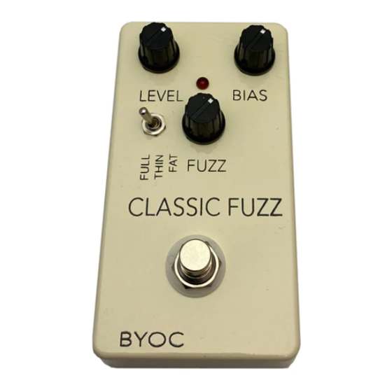
Parts Checklist for BYOC Classic Fuzz Kit Resistors: Metal Film Carbon Composition 1 - 47R (Yellow/Purple/Black/Gold/Brown) (Yellow/Purple/Black/Gold) 1 - 330R (Orange/Orange/Black/Black/Brown) (Orange/Orange/Brown/Gold) 1 - 1k (Brown/Black/Black/Brown/Brown) (Brown/Black/Red/Gold) 2 - 4.7k (Yellow/Purple/Black/Brown/Brown) (Yellow/Purple/Red/Gold) 1 - 33k (Orange/Orange/Black/Red/Brown) (Orange/Orange/Orange/Gold) 1 - 100k... - Page 6 This is what your Classic Fuzz will look like when you are finished.
-
Page 7: Populating The Circuit Board
Populating the Circuit Board Step1: Add the resistors. Resistors will be blue or tan colored and have multicolored bands on them. See the parts list above to read the colors to value table. Resistors are not polarized so they can go in the PCB in either direction... - Page 8 Step 2: Add the larger black plastic diode with silver stripe (1N4001). Make sure the stripe matches up with the layout on the PCB. The cathode (striped end) goes in the square solder pad. The anode goes in the round solder pad.
- Page 9 Step 3: Add the transistors. Transistors are the three-leg components with a curved face. Be sure to line up the curved face on the transistors with the outline on the PCB, as highlighted below.
- Page 10 Step 4: Add the film and ceramic disc capacitors. The film capacitors will have two legs and a red, rounded-square body. The ceramic disc capacitor will also have two legs, but will usually be blue or yellow and have a circular body. These are not polarized and can be inserted in any orientation.
- Page 11 Step 5: Add the aluminum electrolytic capacitors. The aluminum electrolytic capacitors will be cylindrical in shape and have two legs. These are polarized meaning there is a positive and negative side. The longer lead will go into the square hole; this is the positive side.
- Page 12 Step 6: Add the battery snap. Thread the solder ends of the battery snap into the strain relief holes from the bottom solder side of the PCB and out through the top. Insert the solder ends of the battery snap wires into the topside of their respective solder pads. Solder on the bottom side of the PCB.
- Page 13 Top of populated board At this point, your board will look like this. If it doesn’t, go back and fix any issues you might have.
- Page 14 Back of populated board This is what the back of your populated board will look like. Note the clean, shiny solder joints, the close trim of the back leads, and the lack of solder bridges or stray bits of solder. If you have long leads on the back-side, or have blobby or dull solder joints, go back over them with a hot soldering iron, also known as ‘reflowing’...
- Page 15 Step 7: Add wires to the IN, OUT, RING, two Ground eyelets, and DC adapter eyelets. Start by cutting five 2.5” pieces of wire, and three 1” pieces. Strip 1/4” off each end and tin the ends. Tinning means to apply some solder to the stripped ends of the wires. This keeps the strands from fraying and primes the wire for soldering.
-
Page 16: Assembly
Main PCB Assembly Step 1: Mount the AC adapter jack to the enclosure. Your kit may come with either an external thread or internal thread. Don’t get confused by this. They still function exactly the same. You just thread the external nut on the outside and the internal nut on the inside. - Page 17 Step 2: Flip the PCB over so that the bottom or solder side is up. Insert the B1k (FUZZ), A100k (VOLUME), B10k (BIAS) potentiometers, the toggle switch, and the LED into the bottom side of the PCB. DO NOT SOLDER ANYTHING YET!!! The LED will have one lead that is longer than the other.
- Page 18 Step 3: Hold the PCB in one hand so that the component side of the PCB is in the palm of your hand and the bottom side with the pots, toggle switch and LED is facing up. Now use your other hand to guide the predrilled enclosure onto the PCB assembly so that the pots and LED all go into their respective holes.
- Page 19 Step 6: Connect the TIP (negative) terminal of the DC adaptor jack to the eyelet on the PCB labeled “-“. Connect the SLEEVE of the DC adaptor jack to the eyelet on the PCB labeled “+”. Connect the battery disconnect terminal of the DC adaptor jack to the eyelet on the PCB labeled “(+)”.
-
Page 20: Wiring
WIRING You will want to place the jacks into the enclosure so the sleeve terminal is facing the right like the picture below. Be sure to remember the lock washers so the jacks don’t spin on their own. Step 1: Install the ¼” Enclosed jacks. Step 2: Install the footswitch. - Page 21 FOOT SWITCH SOLDER LUG DESIGNATIONS Step 3: Wiring the foot switch. Make a jumper between lugs 3 & 6 from clippings from the resistors. • Simply use your needle nose pliers to make a U shape & insert into lugs 3 &...
- Page 22 Cut a 1.5” piece of wire. Strip 1/8” of one end. Strip 1/2” off the • other end. Tin both ends. This will be used to connect lug/eyelet 4. The longer stripped end will be used to jumper lug 4 to 9.
- Page 23 Cut two 1” pieces of wire. Strip 1/8” off each end and tin. These will • be used to connect lugs/eyelets 1 & 7 Cut three 1.25” pieces of wire. Strip 1/8” off each end and tin. This • will be used to connect lugs/eyelets 2, 5, & 8...
- Page 24 Step 4: Install the foot switch into the enclosure if it isn’t already. Insert the foot switch wires into their respective eyelets on the PCB. You can insert them into the top side and solder on the top side as well. The solder pads should be large enough (if you are using a soldering iron that isn’t too big) to allow you to do this without burning the PVC coating on the wires if you are careful.
- Page 26 Operating Overview Level: This controls the overall output volume. Bias: This controls the voltage to Q2. Use it to adjust the characteristic of the fuzz effect. Fuzz: This controls the amount of fuzz in the effect. Tone Toggle: This allows you to select between three different input capacitors to fine tune the overall tone of the effect;...
-
Page 28: Pcb Map
PCB Map The numbers above correspond to the component numbers on the schematic above. This will help troubleshoot any issues you might have after your build is complete.
Need help?
Do you have a question about the Classic Fuzz and is the answer not in the manual?
Questions and answers