Advertisement
Quick Links
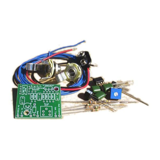
Build Your Own Clone
Confidence Booster
Kit Instructions
Warranty:
BYOC, Inc. guarantees that your kit will be complete and that all parts and components
will arrive as described, functioning and free of defect. Soldering, clipping, cutting,
stripping, or using any of the components in any way voids this guarantee. BYOC, Inc.
guarantees that the instructions for your kit will be free of any majors errors that would
cause you to permanently damage any components in your kit, but does not guarantee
that the instructions will be free of typos or minor errors. BYOC, Inc. does not warranty
the completed pedal as a whole functioning unit, nor do we warranty any of the
individual parts once they have been used. If you have a component that is used, but feel
it was defective prior to you using it, we reserve the right to determine whether or not the
component was faulty upon arrival. Please direct all warranty issues to:
sales@buildyourownclone.com This would include any missing parts issues.
Return:
BYOC, Inc. accepts returns and exchanges on all products for any reason, as long as they
are unused. We do not accept partial kit returns. Returns and exchanges are for the full
purchase price less the cost of shipping and/or any promotional pricing. Return shipping
is the customer's responsibility. This responsibility not only includes the cost of
shipping, but accountability of deliver as well. Please contact
sales@buildyourownclone.com to receive a return authorization before mailing.
Tech Support:
BYOC, Inc. makes no promises or guarantees that you will successfully complete your
kit in a satisfactory manor. Nor does BYOC, Inc. promise or guarantee that you will
Advertisement

Related Manuals for BYOC Confidence Booster


Summary of Contents for BYOC Confidence Booster
- Page 1 BYOC, Inc. does not warranty the completed pedal as a whole functioning unit, nor do we warranty any of the individual parts once they have been used.
- Page 2 That being said, we will do our best to help you as much as we can. Our philosophy at BYOC is that we will help you only as much as you are willing to help yourself. We have a wonderful and friendly DIY discussion forum with an entire section devoted to the technical support and modifications of BYOC kits.
- Page 3 Confidence Booster Kit Instruction Index Parts Checklist……………………………………….page 4 Populating the Circuit Board……………………….page 7 Wiring………………………………………………..page 13 Schematic……………………………………………page 18...
- Page 4 Parts Checklist for the Confidence Booster Kit Resistors 1% metal film has a light blue body and 5 bands. 5% carbon film has a light brown body and 4 bands. Your kit may come with one or both types. 1 - 360 Ohm...
- Page 5 Understanding Resistors When reading 4 band resistor code, you take the first 2 bands at face value. The 3rd band tells you how many zeros to add to the end. And the 4th band tells you the tolerance of the resistor. What is tolerance? Tolerance means how close the component will likely be to its intended value.
- Page 6 Greek word ‘mikrós’, which means small. The ‘F’ is for Farad. You will also see “uF” or “mF” as the symbol for microfarads since many text editors don't have a proper µ. From here on out, and in all other BYOC documents, you'll see microfarads referred to as uf.
-
Page 7: Populating The Circuit Board
Populating the Circuit Board Step 1: Add the resistors. You want to add the components with the lowest profile first so that when you flip the PCB over to solder, the components don't fall out. Resistors are not polarized (polarized means it has a positive and negative end) so you can insert them into the board either way. - Page 8 Step 2: Add the diode. The end with the stripe on it is called the cathode. This end goes into the square solder pad and stripe on the diode and stripe on the layout should match up. The other end of the diode is called the anode.
- Page 9 Step 3: Add the Opamp. Op amps come with two markers to help you determine how to orientate the component. The first is a notch in one end of the chip. If your chip has a notch on one end, insert it into the PCB so that it matches up with the notch in the layout. The other marker is a dot in one corner.
- Page 10 Step 4: Add the trimpot. The trimpot will have 3 leads. The PCB has eyelets for 5 leads. This is so that the PCB can accept a variety of pinout styles. There will only be one way that the trimpot can fit into the PCB. How to set the trimpot: The trimpot is the output volume control.
- Page 11 Step 5: Add the transistor. Match the curved side of the transistor up with the curve side of the layout. A TO-92 package transistor such as the 2N5088 will have 3 leads - the emitter, base, and collector. They are marked on the PCB with E, B, and C.
- Page 12 Step 6: Add the aluminum electrolytic capacitors. Your kit may come with a value between 1uf and 220uf. Aluminum electrolytic capacitors are polarized. The longer lead goes in the square solder pad.
- Page 13 Step 6: Add the film capacitors. These are not polarized and can go in either direction.
- Page 14 Wiring Your kit may come with a variety of input/output jacks. They are all wired slightly different, but all do the exact same thing. Your kit will usually come with a matching pair, but if your kit comes with a mix, follow the wiring for that jack.
- Page 17 Nothing more. Very simple. We suggest that you visit the BYOC forum board.buildyourownclone.com if you'd like someone to take a look at your build and give you any pointers on areas for improvement.
- Page 19 Please visit http://byocelectronics.com/board For any technical support Copyright 2017 BYOC, Inc.
Need help?
Do you have a question about the Confidence Booster and is the answer not in the manual?
Questions and answers