Advertisement
Quick Links
Warranty:
BYOC, INC guarantees that your kit will be complete and that all parts and
components will arrive as described, functioning and free of defect. Soldering,
clipping, cutting, stripping, or using any of the components in any way voids this
guarantee. BYOC, INC guarantees that the instructions for your kit will be free of
any majors errors that would cause you to permanently damage any components
in your kit, but does not guarantee that the instructions will be free of typos or
minor errors. BYOC, INC does not warranty the completed pedal as a whole
functioning unit, nor do we warranty any of the individual parts once they have
been used. If you have a component that is used, but feel it was defective prior to
you using it, we reserve the right to determine whether or not the component was
faulty upon arrival. Please direct all warranty issues to:
sales@buildyourownclone.com This would include any missing parts issues.
Return:
BYOC, LLC accepts returns and exchanges on all products for any reason, as long as they
are unused. We do not accept partial kit returns. Returns and exchanges are for the full
purchase price less the cost of shipping and/or any promotional pricing. Return shipping
is the customer's responsibility. This responsibility not only includes the cost of
Build Your Own Clone
Chancellor Overdrive
Kit Instructions
1
Advertisement

Related Manuals for BYOC Chancellor Overdrive


Summary of Contents for BYOC Chancellor Overdrive
- Page 1 This would include any missing parts issues. Return: BYOC, LLC accepts returns and exchanges on all products for any reason, as long as they are unused. We do not accept partial kit returns. Returns and exchanges are for the full purchase price less the cost of shipping and/or any promotional pricing.
- Page 2 That being said, we will do our best to help you as much as we can. Our philosophy at BYOC is that we will help you only as much as you are willing to help yourself. We have a wonderful and friendly DIY discussion forum with an entire section devoted to the technical support and modifications of BYOC kits.
-
Page 3: Table Of Contents
CHANCELLOR OVERDRIVE KIT INSTRUCTION INDEX Parts Checklist………………………………………page 5-6 Populating the Circuit Board………………………page 7-14 Main PCB Assembly………………………………..page 15-19 Wiring………………………………………………..page 20-27 Installing the IC's and Finishing Up………………page 28 Operation Overview………………………………..page 29 Schematic……………………………………………page 30... - Page 4 Chancellor Final Stock Build...
-
Page 5: Parts Checklist
BYOC Chancellor Overdrive Kit Parts Checklist Resistors: 1 - 100ohm (brown/black/black/black/brown) 2 - 680ohm (blue/gray/black/black/brown) 1 - 1k (brown/black/black/brown/brown) 1 - 1k5 (brown/green/black/brown/brown) 1 - 2k2 (red/red/black/brown/brown) (one extra for modification) 3 - 4k7 (yellow/purple/black/brown/brown) 1 - 22k (red/red/black/red/brown) 2 - 47k (yellow/purple/black/red/brown) - Page 6 1 - B100k linear (GAIN) 1 - B100k linear (VOLUME) Hardware: 1 - drilled enclosure w/ 4 screws (optional) 1 - BYOC Chancellor overdrive PCB 1 - 3PDT footswitch 3 - knobs (optional) 1 - AC adaptor jack (optional) 1 - LED (optional) 1 - ¼”mono jack...
-
Page 7: Populating The Circuit Board
Populating the Circuit Board STEP 1: Add the resistors. Resistors are not polarized, so it does not matter which end goes in which solder pad. Take your time and be sure not to confuse similarly banded resistors such as the 100ohm with the 100k or the 680ohm with the 680k. This is a very common mistake. - Page 8 STEP 2: Add the 8 pin IC socket. ONLY SOLDER THE SOCKET! NOT THE ACTUAL IC! This is a socket. The sockets get soldered to the PCB. The ICs get inserted into the sockets. The actual IC chip itself, never gets soldered. You will insert the IC into the socket after the entire pedal has been built.
- Page 9 STEP 3: Add the 2 red LEDs. These provide the signal clipping. The LEDs will have one lead that is longer than the other. The longer lead goes in the square solder pad hole. The shorter lead goes in the round solder pad hole.
- Page 10 Step 4: Add the film and ceramic disc capacitors. These are not polarized and can be installed in any orientation, as long as the value is correct. The spots highlighted in YELLOW are the ceramic disc capacitors. The spot highlighted in BLUE is to be left empty.
- Page 11 STEP 5: Add the aluminum electrolytic capacitors. These are polarized. The positive end will have a longer lead and should go in the square solder pad. The negative end will have a shorter lead with a black or white stripe running down the body of the capacitor.
- Page 12 By this time, your PCB should look like this...
- Page 13 Step 6: Add the battery snap. Thread the solder ends of the battery snap into the strain relief holes from the bottom solder side of the PCB and out through the top. Insert the solder ends of the battery snap wires into the topside of their respective solder pads.
- Page 14 Step 7: Add wires to the IN, OUT, RING, and two Ground eyelets. Start by cutting four 2.5” pieces of wire and one 1.5” piece of wire. Strip 1/4” off each end and tin the ends. Tinning means to apply some solder to the stripped ends of the wires. This keeps the strands from fraying and primes the wire for soldering.
-
Page 15: Main Pcb Assembly
Main PCB Assembly Step 1: Mount the DC adapter jack to the enclosure. NOTE: You may wish to install the three ¾ in. wires used to connect the adapter to the PCB in Step 6 before mounting. - Page 16 Step 2: Flip the PCB over so that the bottom or solder side is up. Insert the B100k(GAIN), B100k(VOLUME), A10k(BASS), A10k(MID), and B10K(TREB) . If your pots have potentiometers, and the LED into the bottom side of the PCB covers, remove them before continuing. You might have to cut a slit in the cover with a blade and use a small screwdriver to get leverage.
- Page 18 Step 4: Turn the entire pedal over so that the component side of the PCB if facing up. Lift the PCB up off the pots and toggle switch about 2mm just to make sure that the back of the PCB does not short out against that pots. Make sure the PCB is level and symmetrically seated inside the enclosure.
- Page 19 Step 6: Connect the TIP (negative) terminal of the DC adaptor jack to the eyelet on the PCB with 3/4 inches of hook up wire. Connect the SLEEVE of the DC adaptor jack to the eyelet on the far right side of the PCB with 3/4 inches of hook up wire. Connect the battery disconnect terminal of the DC adaptor jack to the eyelet more towards the center of the PCB with 3/4 of hookup wire.
-
Page 20: Wiring
Wiring Stereo (input) Jack Mono (output) Jack Step 1: Install the 1/4” jacks to the enclosure. - Page 21 Step 2: Install the footswitch. Orient the footswitch so that the flat sides of the solder lugs are like the diagram below. NOTE: There are no actual number markings on the footswitch. There are two correct ways you can orient the footswitch. They are both 180 degrees of each other.
- Page 22 FOOT SWITCH SOLDER LUG DESIGNATIONS...
- Page 23 Step 3: Wiring the foot switch. • Make a jumper between lugs 3 & 6 from clippings from the resistors. Simply use your needle nose pliers to make aU shape & insert into lugs 3 & 6, then solder.
- Page 24 Cut 1 x 1.5” piece of wire. Strip 1/8” of one end. Strip 1/2” off the other end. This will be used to connect lug/eyelet 4. The longer stripped end will be used to jumper lug 4 to 9. Step 3: Wiring the foot switch. Cut 4 x 1”...
- Page 25 Step 4: Solder one end of the pre-cut and pre-stripped wires to the footswitch.
- Page 26 Step 5: Connect the pre stripped and tinned wires to the 1/4” jacks. NOTE: Wires shown in black & red are merely to indicate ground wires & positive power wires, respectfully. Your kit provides purple wire; you may choose to detonate these in a wire color of your choice.
- Page 27 Step 6: Insert the other remaining ends of the pre-cut and pre-stripped wires into the topside of the PCB and solder. You can solder these on the topside as well. It is easier this way, but you may burn a small amount of the PVC coating on the wires. This is purely aesthetic and won't damage the wires in anyway.
-
Page 28: Installing The Ic's And Finishing Up
Installing the IC's and Finishing Up Don't forget to put the cover on the enclosure and apply the bumpers to the cover if you like to use them. -
Page 29: Operation Overview
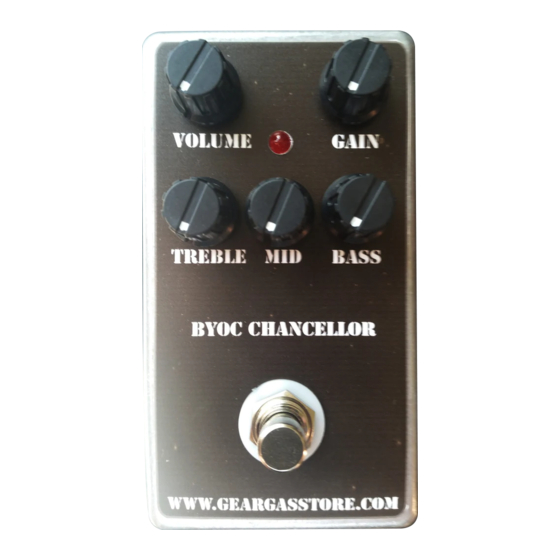
Operating Overview Gain: Adjusts the amount of overdrive. Lower settings (7 to 11 o’clock) produce a nice boost without getting crunchy. At the noon/1 o’clock position, classic, fat rock tones that will thicken up even single coils. From 2 to 4 o’clock, metal type rage, especially with humbuckers. - Page 31 Click here for hi res schematic or go to www.byocelectronics.com/chancellorscheme.pdf Please visit http://byocelectronics.com/board for any technical support Copyright 2020 BYOC, Inc.
Need help?
Do you have a question about the Chancellor Overdrive and is the answer not in the manual?
Questions and answers