Advertisement
Quick Links
Build Your Own Clone
Classic Phaser
Kit Instructions
Warranty:
BYOC, Inc. guarantees that your kit will be complete and that all parts and components
will arrive as described, functioning and free of defect. Soldering, clipping, cutting,
stripping, or using any of the components in any way voids this guarantee. BYOC, INC
guarantees that the instructions for your kit will be free of any majors errors that would
cause you to permanently damage any components in your kit, but does not guarantee
that the instructions will be free of typos or minor errors. BYOC, INC does not
warranty the completed pedal as a whole functioning unit, nor do we warranty any of the
individual parts once they have been used. If you have a component that is used, but feel
it was defective prior to you using it, we reserve the right to determine whether or not the
component was faulty upon arrival. Please direct all warranty issues to:
sales@buildyourownclone.com This would include any missing parts issues.
Return:
BYOC, Inc. accepts returns and exchanges on all products for any reason, as long as they
are unused. We do not accept partial kit returns. Returns and exchanges are for the full
purchase price less the cost of shipping and/or any promotional pricing. Return shipping
is the customer's responsibility. This responsibility not only includes the cost of
shipping, but accountability of deliver as well. Please contact
sales@buildyourownclone.com to receive a return authorization before mailing.
Advertisement

Related Manuals for BYOC Classic Phaser


Summary of Contents for BYOC Classic Phaser
- Page 1 This would include any missing parts issues. Return: BYOC, Inc. accepts returns and exchanges on all products for any reason, as long as they are unused. We do not accept partial kit returns. Returns and exchanges are for the full purchase price less the cost of shipping and/or any promotional pricing.
- Page 2 That being said, we will do our best to help you as much as we can. Our philosophy at BYOC is that we will help you only as much as you are willing to help yourself. We have a wonderful and friendly DIY discussion forum with an entire section devoted to the technical support and modifications of BYOC kits.
-
Page 3: Table Of Contents
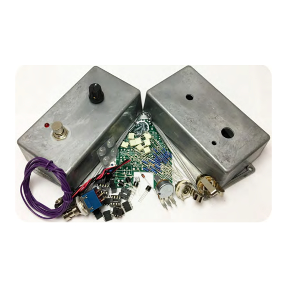
Classic Phaser Kit Instruction Index Parts Checklist………………………....…..page 6 Populating the Circuit Board……....…...…..page 8 Main PCB Assembly..........page 16 Wiring………………………………......page 19 Installing the IC/Finishing up…………………..page 25 Operation Overview...........page 26 Schematic..............page 27... - Page 4 This is what your kit should look like when it’s complete. Your kit may come with different color capacitors, switches etc. Don’t be alarmed by this. They all still do the exact same thing.
-
Page 5: Parts Checklist
Parts Checklist for Classic Phaser Kit Resistors: 2 - 4k7 (Yellow/Purple/Black/Brown/Brown) 10 - 10k (Brown/Black/Black/Red/Brown) 5 - 22k (Red/Red/Black/Red/Brown) 1 - 56k (Green/Blue/Black/Red/Brown) 6 - 150k (Brown/Green/Black/Orange/Brown) 2 - 470k (Yellow/Purple/Black/Orange/Brown) 1 - 1M (Brown/Black/Black/Yellow/Brown) 1 - 3.9M (Orange/White/Green/Gold) Visit www.byocelectronics.com/resistorcodes.pdf... - Page 6 PAIR OF NEEDLE NOSE PLIERS 1 - C500k 1 - 250k Trimpot Hardware: 1 - predrilled enclosure w/ 4 screws 1 - Classic Phaser circuit board 1 - 3pdt footswitch 1 - Knob 1 - AC adapter jack 1 - ¼”stereo jack 1 - ¼”...
-
Page 7: Populating The Circuit Board
Populating the Circuit Board Step 1: Add all the resistors. Resistors are not polarized and can be inserted in either direction. Note: Leave out the 22k resistor highlighted in yellow for ‘script logo’ specs, add it for the later ‘block logo’ specs. - Page 8 Add the diode. Be sure to match the end of the diode with the stripe to Step 2: the layout on the PCB. The striped end should go in the square solder pad.
- Page 9 Add 4 pin IC sockets. ONLY SOLDER THE SOCKET! NOT Step 3: THE ACTUAL IC! This is a socket. The sockets get soldered to the PCB. The ICs get inserted into the sockets. The actual IC chip itself, never gets soldered.
- Page 10 Step 4: Add the transistors. Orient them so that the flat side matches up with the flat side on the PCB layout. The transistor highlighted in yellow is the PNP transistor. The transistors highlighted in red are the JFETs...
- Page 11 Step 6: Add the film capacitors. These are non-polarized so it can go in either direction.
- Page 12 Step 7: Add the trimpot. When your build is complete, you will ‘dial in’ the trimpot so that you get the best sounding phase effect. First, set the trimpot to noon, and slowly turn it in either direction until you find the range of phase effect. Typically the best setting would be in the middle of said range.
- Page 13 Step 8: Add the aluminum electrolytic capacitors. These ARE polarized, meaning there is a positive and negative end. The positive side will have a longer lead and goes in the square solder pad. The negative side will have a shorter lead and a stripe running along the body of the cap, and goes in the round solder pad.
- Page 14 Step 9: Add the battery snap. Thread the solder ends of the battery snap through the strain relief holes from the bottom solder side of the PCB and out through the top. Insert the solder ends of the battery snap wires into the topside of their respective solder pads.
- Page 15 Step 10: Add wires to the IN, OUT, RING, and two Ground eyelets. Start by cutting four 2.5” pieces of wire, and one 1.5” piece. Strip 1/4” off each end and tin the ends. Tinning means to apply some solder to the stripped ends of the wires. This keeps the strands from fraying and primes the wire for soldering.
-
Page 16: Main Pcb Assembly
Main PCB Assembly Step 1: Mount the AC adapter jack to the enclosure. Your kit may come with either an external thread or internal thread. Don’t get confused by this. They still function exactly the same. You just thread the external nut on the outside and the internal nut on the inside. - Page 17 Step 2: Flip the PCB over so that the bottom or solder side is up. Insert the potentiometer and the LED into the bottom side of the PCB. DO NOT SOLDER ANYTHING YET!!! The LED will have one lead that is longer than the other.
- Page 18 Step 3: Hold the PCB in one hand so that the component side of the PCB is in the palm of your hand and the bottom side with the pots, toggle switch and LED is facing up. Now use your other hand to guide the predrilled enclosure onto the PCB assembly so that the pots and LED all go into their respective holes.
- Page 19 Step 5: Solder the pots and LED. You will solder these parts on the component side of the PCB. After you have soldered them in place, be sure to tighten up their nuts.
-
Page 20: Wiring
Wiring Step 6: Connect the TIP (negative) terminal of the DC adaptor jack to the eyelet on the PCB labeled “-“. Connect the SLEEVE of the DC adaptor jack to the eyelet on the PCB labeled “+” farthest to the right. Connect the battery disconnect terminal of the DC adaptor jack to the second eyelet on the PCB labeled “+”... - Page 21 Stereo (input) Jack Mono (output) Jack Step 1: Install the 1/4” jacks to the enclosure.
- Page 22 Step 2: Install the footswitch. Orient the footswitch so that the flat sides of the solder lugs are like the diagram below. NOTE: There are no actual number markings on the footswitch. There are two correct ways you can orient the footswitch. They are both 180 degrees of each other.
- Page 23 FOOT SWITCH SOLDER LUG DESIGNATIONS Step 3: Wiring the foot switch. Make a jumper between lugs 3 & 6 from clippings from the resistors. • Simply use your needle nose pliers to make a U shape & insert into lugs 3 &...
- Page 24 Cut two 1” pieces of wire. Strip 1/8” off each end and tin. These will • be used to connect lugs/eyelets 1 & 7 Cut three 1.25” pieces of wire. Strip 1/8” off each end and tin. This • will be used to connect lugs/eyelets 2, 5, & 8 Step 4: Install the foot switch into the enclosure if it isn’t already.
- Page 25 Step 5: Connect the pre stripped and tinned wires to the 1/4” jacks and connect the wires from the footswitch to the PCB. The wire from the IN eyelet goes to the tip of the stereo jack. The wire from the RING eyelet goes to the ring of the stereo jack.
- Page 26 Installing IC/Finish up Install the ICs into their sockets. Orient the ICs as shown in the diagram below. You will most likely need to bend the pins of the ICs in just a little before installing. Don't forget to add the knobs, put the cover on the enclosure, and apply the bumpers to the cover.
-
Page 27: Operation Overview
Operating Overview SPEED: This controls the speed of the effect. All-the-way counter-clockwise is the slowest speed, all-the-way clockwise is the fastest. Power supply: 9V battery or 2.1mm negative tip Current Draw: 3.5mA Input Impedance: 100k ohms Output Impedance: 100k ohms... - Page 29 For hi-res schematic visit http://www.byocelectronics.com/classicphaserschematic.pdf Please visit http://byocelectronics.com/board For any technical support Copyright 2017 BYOC, Inc.
Need help?
Do you have a question about the Classic Phaser and is the answer not in the manual?
Questions and answers