Advertisement
Quick Links
Build Your Own Clone
Analog Vibrato
Kit Instructions
Warranty:
BYOC, Inc. guarantees that your kit will be complete and that all parts and components
will arrive as described, functioning and free of defect. Soldering, clipping, cutting,
stripping, or using any of the components in any way voids this guarantee. BYOC, INC
guarantees that the instructions for your kit will be free of any majors errors that would
cause you to permanently damage any components in your kit, but does not guarantee
that the instructions will be free of typos or minor errors. BYOC, INC does not
warranty the completed pedal as a whole functioning unit, nor do we warranty any of the
individual parts once they have been used. If you have a component that is used, but feel
it was defective prior to you using it, we reserve the right to determine whether or not the
component was faulty upon arrival. Please direct all warranty issues to:
sales@buildyourownclone.com This would include any missing parts issues.
Return:
BYOC, Inc. accepts returns and exchanges on all products for any reason, as long as they
are unused. We do not accept partial kit returns. Returns and exchanges are for the full
purchase price less the cost of shipping and/or any promotional pricing. Return shipping
is the customer's responsibility. This responsibility not only includes the cost of
shipping, but accountability of deliver as well. Please contact
sales@buildyourownclone.com to receive a return authorization before mailing.
Tech Support:
BYOC, Inc. makes no promises or guarantees that you will successfully complete your
kit in a satisfactory manor. Nor does BYOC, Inc. promise or guarantee that you will
receive any technical support. Purchasing a product from BYOC, Inc. does not entitle
Advertisement

Related Manuals for BYOC Analog Vibrato


Summary of Contents for BYOC Analog Vibrato
- Page 1 This would include any missing parts issues. Return: BYOC, Inc. accepts returns and exchanges on all products for any reason, as long as they are unused. We do not accept partial kit returns. Returns and exchanges are for the full purchase price less the cost of shipping and/or any promotional pricing.
- Page 2 That being said, we will do our best to help you as much as we can. Our philosophy at BYOC is that we will help you only as much as you are willing to help yourself. We have a wonderful and friendly DIY discussion forum with an entire section devoted to the technical support and modifications of BYOC kits.
-
Page 3: Table Of Contents
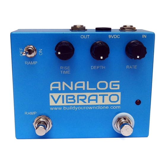
Analog Vibrato Kit Instruction Index Parts Checklist………………………....…..page 6 Populating the Circuit Board……....…...…..page 8 Main PCB Assembly..........page 17 Wiring………………………………......page 20 Operation Overview...........page 26 Schematic..............page 27... - Page 4 This is what your kit should look like when it’s complete. Your kit may come with different color capacitors, switches ect. Don’t be alarmed by this. They all still do the exact same thing.
-
Page 5: Parts Checklist
Parts Checklist for the Analog Vibrato Kit Resistors: (Metal Film (5 Bands) / Carbon Film (4 Bands)) 1 - 100R (Brown/Black/Black/Black/Brown) / (Brown/Black/Brown/Gold) 3 - 1k (Brown/Black/Black/Brown/Brown) / (Brown/Black/Red/Gold) 1 - 1k8 (Brown/Gray/Black/Brown/Brown) / (Brown/Gray/Red/Gold) 1 - 2k7 (Red/Purple/Black/Brown/Brown) / (Red/Purple/Red/Gold) - Page 6 1 - B50k (DEPTH) 1 - C250k (RATE) Hardware: 1 - predrilled enclosure w/ 4 screws 1 - Analog Vibrato Printed Circuit Board 1 - Momentary SPST footswitch 1 - 3PDT Footswitch 1 - SPDT On-On Toggle Switch 2 - Enclosed Jacks...
-
Page 7: Populating The Circuit Board
Populating the Circuit Board Step 1: Add all the resistors. Resistors are not polarized and can be inserted into the PCB in either direction, meaning you don’t have to worry about orienting them. - Page 8 Step 2: Add the diodes. Be sure to match the end of the diodes with the stripe to the layout on the PCB. The striped ends should go in the square solder pads.
- Page 9 Step 3: Add the IC sockets. Be sure to align the notch on the IC sockets with the notch on the PCB screenprint. The SIP-9 socket won’t have any indicator, so the orientation of the BA6110 is important. Pin 1 of the BA6110 will go in the square hole which also has a screenprinted square around it.
- Page 10 Step 4: Add the transistors. Be sure to match the flat side of the transistors with the flat side on PCB layout. The transistors highlighted in RED are the 2N3904. The transistors highlighted in YELLOW are the 2N3906.
- Page 11 Step 5: Add the film and ceramic disc capacitors. These are non-polarized so they can go in either direction. The ceramic disc capacitors are highlighted in yellow, and are also non-polarized.
- Page 12 Step 6: Add the aluminum electrolytic capacitors. These ARE polarized, meaning there is a positive and negative end. The positive side will have a longer lead and goes in the square solder pad. The negative side will have a shorter lead and a stripe running along the body of the cap, and goes in the round solder pad.
- Page 13 Step 7: Add the trimpots. There are 5 holes, but only three legs on the trimpots. This is normal. Your trimpot will only fit into three holes; the additional holes are to accommodate various sizes of trimpots. Setting the trimpots: When you are done with your build, and ready to use the pedal, you will use these to control the bias and delay time.
- Page 14 Step 8: Add the battery snap. Thread the wires into the strain relief holes first through the bottom side of the PCB. Then insert the leads into their respective solder pad hole on the top-side of the PCB. The red lead goes in the + hole and the black lead goes in the –...
- Page 15 At this point, your build will look like this:...
-
Page 16: Main Pcb Assembly
Main PCB Assembly Step 1: Flip the PCB over so that the bottom or solder side is up. Insert the potentiometers, toggle switches, and the LEDs into the bottom side of the PCB. DO NOT SOLDER ANYTHING YET!!! (See below for advanced tip) The LED will have one lead that is longer than the other. - Page 17 Step 2: Hold the PCB in one hand so that the component side of the PCB is in the palm of your hand and the bottom side with the pots, toggle switch and LED is facing up. Now use your other hand to guide the predrilled enclosure onto the PCB assembly so that the pots, toggle switch and LED all go into their respective holes.
- Page 18 You will want to place the jacks into the enclosure so the sleeve terminal is facing the right like the picture above. Be sure to remember the lock washers so the jacks don’t spin on their own. Step 5: Install the footswitch. Orient the footswitch so that the flat sides of the solder lugs are like the diagram below.
- Page 19 FOOT SWITCH SOLDER LUG DESIGNATIONS Step 5a: Make a jumper between lugs 3 & 6 from clippings from the resistors. Simply use your needle nose pliers to make a U shape & insert into lugs 3 & 6, then solder. Step 5b: Connect a wire to LUG 4 that also jumpers to LUG9.
-
Page 20: Wiring
WIRING Step 6: Connect the TIP (negative) terminal of the DC adapter jack to the eyelet on the PCB labeled “-“. Connect the SLEEVE of the DC adapter jack to the eyelet on the PCB labeled “+” farthest to the right. Connect the BATTERY lug to the eyelet in-between the “-“... - Page 21 Finished Wiring.
-
Page 22: Operation Overview
Operating Overview RAMP TOGGLE: Turns the ramp feature on or off. When the ramp is ON, use the ramp footswitch to activate the effect. When the ramp is OFF, the pedal acts as a normal vibrato. RISE TIME: Controls the speed in which the effect turns on when in RAMP ON mode. CCW = Faster onset of vibrato effect. - Page 24 For hi-res schematic visit: http://byocelectronics.com/analogvibratoschematic.pdf Please visit http://byocelectronics.com/board For any technical support Copyright 2018 BYOC, Inc.
Need help?
Do you have a question about the Analog Vibrato and is the answer not in the manual?
Questions and answers