Table of Contents
Advertisement
Available languages
Available languages
Quick Links
Istruzioni d'uso e manutenzione valvole Serie F
Made in Italy
I prodotti risultano essere in conformità con quanto previsto dalle seguenti direttive comunitarie:
-
2004/108/CE
Essi rispondono per intero o per le sole parti applicabili alle seguenti norme armonizzate:
-
CEI EN 61000-6-2 Compatibilità elettromagnetica.Parte 6-1: Norme generiche - Immunità per
gli ambienti industriali.
-
CEI EN 61000-6-4 Compatibilità elettromagnetica.Parte 6-3: Norme generiche - Emissione per
gli ambienti industriali.
e alle seguenti norme tecniche:
-
EN ISO 4414
Dal sito
www.camozzi.com
Istruzioni d'uso e manutenzione
Valvole serie F
sono scaricabili le Dichiarazioni CE di Conformità
93-7507-0014
Revisione B
Advertisement
Table of Contents

Related Manuals for Camozzi F Series


Summary of Contents for Camozzi F Series
- Page 1 CEI EN 61000-6-2 Compatibilità elettromagnetica.Parte 6-1: Norme generiche - Immunità per gli ambienti industriali. CEI EN 61000-6-4 Compatibilità elettromagnetica.Parte 6-3: Norme generiche - Emissione per gli ambienti industriali. e alle seguenti norme tecniche: EN ISO 4414 Dal sito www.camozzi.com sono scaricabili le Dichiarazioni CE di Conformità...
- Page 2 93-7507-0014 Istruzioni d'uso e manutenzione Valvole serie F Revisione B 1. Identificazione del prodotto...
-
Page 3: Raccomandazioni Generali
E' raccomandato l'uso di apposite protezioni per minimizzare il rischio di lesioni alle persone. Per tutte quelle situazioni di utilizzo non contemplate in questo manuale e in situazioni in cui potrebbero essere causati danni a cose, persone o animali, contattare prima Camozzi... - Page 4 Il prodotto può essere messo in esercizio solo nel rispetto delle specifiche indicate, se queste specifiche non vengono rispettate il prodotto può essere messo in funzione solo dopo autorizzazione da parte di Camozzi. Per ridurre il rumore causato dall’aria scaricata dal componente, prevedere l’utilizzo di appositi silenziatori o convogliare il fluido in una zona in cui, durante il normale funzionamento, non si ha la presenza di addetti.
- Page 5 93-7507-0014 Istruzioni d'uso e manutenzione Valvole serie F Revisione B 3. Caratteristiche e condizioni di utilizzo generali Caratteristiche e condizioni di utilizzo generali Costruzione valvola A spola con guarnizioni Funzioni valvola 5/2 monostabile e bistabile 5/3 CC; 2x2/2 NO; 2x2/2 NC 1x2/2 NC + 1x2/2 NO 2x3/2 NO;...
-
Page 6: Installazione E Messa In Servizio
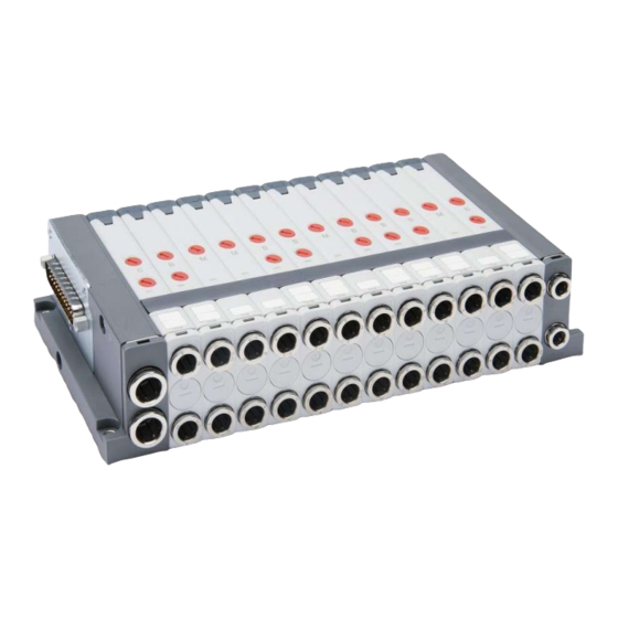
93-7507-0014 Istruzioni d'uso e manutenzione Valvole serie F Revisione B 4. Trasporto e stoccaggio del prodotto Adottare tutti gli accorgimenti possibili per evitare il danneggiamento accidentale del prodotto durante il trasporto, in caso siano disponibili utilizzare gli imballi originali Rispettare il campo di temperatura per lo stoccaggio di -10 ÷ 50 °C 5. - Page 7 93-7507-0014 Istruzioni d'uso e manutenzione Valvole serie F Revisione B 5.1 Descrizione componenti ELENCO COMPONENTI Viti di serraggio con rondella integrata Squadretta per fissaggio guida DIN Terminale sinistro Tiranti Profilo copri cava tirante Elettrovalvola bistabile Elettrovalvola monostabile Piastra intermedia posizione libera Piastra intermedia zone di pressione alimentazione e scarico supplementare Terminale destro...
- Page 8 93-7507-0014 Istruzioni d'uso e manutenzione Valvole serie F Revisione B 5.2 Connessioni pneumatiche: Esempio di isola con pressioni e scarico differenziati Legenda disegno: A = servopilotaggio di tipo interno B = servopilotaggio di tipo esterno X = alimentazione e scarico supplementari K = alimentazione supplementare, scarico separato U = alimentazione separata, scarico supplementare T = alimentazione e scarico separati...
- Page 9 93-7507-0014 Istruzioni d'uso e manutenzione Valvole serie F Revisione B 5.3 Istruzioni per il fissaggio e l'ancoraggio Utilizzare gli appositi elementi PCF-E520 (punto 2 dell’elenco componenti), da montare sul retro dei terminali destro e sinistro, per il fissaggio dell’isola di valvole Serie F su canalina DIN . L’isola di valvole serie F può...
- Page 10 93-7507-0014 Istruzioni d'uso e manutenzione Valvole serie F Revisione B 5.5 Esempio di corrispondenza tra i pin del connettore D-sub 25 poli e i solenoidi delle valvole F P = Pin Connettore S = Solenoide valvola Pin 1..24 = Comando solenoidi (+24 V dc) Pin 25 = Comune negativo (0 Vdc) Tipo di valvola Descrizione...
- Page 11 Il prodotto può essere messo in esercizio solo nel rispetto delle specifiche indicate, se queste specifiche non vengono rispettate il prodotto può essere messo in funzione solo dopo autorizzazione da parte di Camozzi. Rispettare le indicazioni riportate sulla targhetta di identificazione.
- Page 12 93-7507-0014 Istruzioni d'uso e manutenzione Valvole serie F Revisione B 6.2 Descrizione comando manuale Per l’azionamento dell’intervento manuale utilizzare un cacciavite a taglio con testa 0,8 x 4 mm conforme alla normativa UNI10562 ISO2380 DIN5265 Comando manuale versione R: Comando manuale versione P: Azionamento a pressione con dispositivo di Azionamento a pressione senza dispositivo di ritenuta (PUSH &...
- Page 13 93-7507-0014 Istruzioni d'uso e manutenzione Valvole serie F Revisione B 6.3 Sostituire o aggiungere una valvola o una piastra di separazione della pressione: A – Rimuovere la copertura del tirante (1) B – Svitare le viti (2) del terminale destro (terminale senza in connettore D-sub). Per evitare indesiderate sollecitazioni meccaniche a plastica e tiranti si consiglia di allentare entrambe le viti prima della completa rimozione C –...
- Page 14 93-7507-0014 Istruzioni d'uso e manutenzione Valvole serie F Revisione B 6.4 Sostituire una connessione pneumatica A – Rimuovere la clip (1) dal corpo valvola tirandola verso l’alto B – Estrarre le boccole (2) e sostituirle D – Rimontare la clip (1) ATTENZIONE: verificare sempre il completo inserimento della clip dopo la sostituzione delle boccole...
- Page 15 8. Limitazioni d'utilizzo Non superare le specifiche tecniche riportate nel paragrafo "Caratteristiche generali" e sul catalogo generale Camozzi. Non installare il prodotto in ambienti in cui l'aria stessa può causare pericoli. A meno di specifiche destinazioni d'uso, non utilizzare il prodotto in ambienti in cui si potrebbe...
-
Page 16: Manutenzione
9.2 Parti di ricambio e accessori: Per l’elenco delle parti di ricambio e di tutti gli accessori vedere il catalogo generale Camozzi 10. Informazioni Ecologiche Alla fine del ciclo di vita del prodotto, si raccomanda la separazione dei materiali per consentirne il recupero. - Page 17 93-7507-0014 Istruzioni d'uso e manutenzione Valvole serie F Revisione B 11.Contatti Camozzi spa Società Unipersonale Via Eritrea, 20/I 25126 Brescia - Italy Tel. +39 030 37921 Fax +39 030 2400464 info@camozzi.com www.camozzi.com Product Certification National and International Directives, Regulations and Standards productcertification@camozzi.com...
- Page 18 CEI EN 61000-6-4 Electromagnetic compatibility (EMC) - Part 6-3: Generic standards - Emission standard for residential, commercial and light-industrial environments and with the following standards and/or technical specifications: EN ISO 4414 The EC Compliance Declarations can be downloaded from www.camozzi.com...
- Page 19 93-7507-0014 Use and maintenance instruction Valves series F Revision 1. Product identification...
-
Page 20: General Safety Instructions
Use appropriate protection to minimize any risk of injury. For situations which are not covered in this manual and for situations where there is the possibility of injury being caused to people or animals, please contact Camozzi before using the product. - Page 21 The product should only be put into operation if all of the Camozzi defined specifications and criteria are met. If they are not met, the product should only be put into operation after receiving approval from Camozzi.
- Page 22 93-7507-0014 Use and maintenance instruction Valves series F Revision 3. General characteristics and conditions of use General characteristics and conditions of use Valve Construction Spool with seals Valve Functions 5/2 monostable e bistable 5/3 CC; 2x2/2 NO; 2x2/2 NC 1x2/2 NC + 1x2/2 NO 2x3/2 NO;...
-
Page 23: Mounting And Commissioning
Close any unused openings with covers or protective caps. The components must be fixed properly, using, where available, the applicable Camozzi brackets so that the device remains fixed even when the actuator operates at high frequency or in the presence of strong vibrations. - Page 24 93-7507-0014 Use and maintenance instruction Valves series F Revision 5.1 Components list COMPONENTS LIST Grip screws with built-in washer Bracket for the DIN rail connection Left terminal Tie-rods Tie-rod plastic cover Bistable valve Monostable valve Intermediate plate for free position Intermediate plate for pressure zones with supplementary inlet and exhaust Right terminal...
- Page 25 93-7507-0014 Use and maintenance instruction Valves series F Revision 5.2 Pneumatic Connection: Example of valve Island with differentiated pressures and exhausts Drawing ledend: A = internal servo-pilot B = external servo-pilot X = supplementary power supply and exhaust K = supplementary power supply, separated exhaust U = supplementary power supply, supplementary exhaust T = separated power supplì...
- Page 26 93-7507-0014 Use and maintenance instruction Valves series F Revision 5.3 Fixing instruction Use the appropriate bracket PCF-E520 (point 2 of the components list), to be mounted on the back of the right and left terminal, for fixing valve island Series F on the DIN rail The valve island Series F can be directly fixed to a support using the holes present on the terminals 5.4 Electrical connection Connect the pre-wired cables to D-sub connector on valve island and tighten the screws...
- Page 27 93-7507-0014 Use and maintenance instruction Valves series F Revision 5.5 Example of electrical pin configuration P = D-sub Connector’s Pin S = Valve’s solenoid Pin 1..24 = Output (+24 V dc) Pin 25 = Negative common (0 Vdc) Valve type Description N°...
- Page 28 The product should only be put into service when all of the operating conditions are within the permissible values; if one of the operating conditions exceeds the limits, the product can only be put into service after receiving official authorization from Camozzi. Observe the specifications written on the identification plate.
- Page 29 93-7507-0014 Use and maintenance instruction Valves series F Revision 6.2 Manual override description To actuate the manual override to use a screwdriver for slotted head screw with dimension 0,8x4, compliant to UNI10562 ISO2380 DIN5265 Manual override, P version: Manual override, R version: Pressure actuation control with PUSH only Pressure actuation control with PUSH &...
- Page 30 93-7507-0014 Use and maintenance instruction Valves series F Revision 6.3 To change or add a valve: A – Remove the cover of the tie rod (1) B – Unscrew the screws (2) on the right side (opposite at the D-sub connector). To avoid undesirable mechanical stress on plastics and ties is advisable to loosen both screws before complete removal C –...
- Page 31 93-7507-0014 Use and maintenance instruction Valves series F Revision 6.4 To change a pneumatic connection A – Remove the clip (1) from the valve B – Extract the cartridge (2) and change it D – Reassemble the clip (1) ATTENTION: Check always the complete insertion of the clip...
-
Page 32: Use Limitations
8. Use limitations Do not exceed the operating conditions illustrated within either the "General Characteristics" section of this document or in the Camozzi product catalogue. Do not install the product in zones where the air can cause hazards. Unless special permission has been granted do not use the product in environments where there... -
Page 33: Maintenance
Clean the equipment with a damp cloth, use only water or mild detergent 9.2 Parts and accessories: For a list of spare parts and accessories see the Camozzi catalogue 10. Ecological information At the end of the life of the product, it is recommended that the materials are separated so that they can be recycled where possible. -
Page 34: Product Certification
93-7507-0014 Use and maintenance instruction Valves series F Revision 11. Contacts Camozzi spa Via Eritrea, 20/I 25126 Brescia - Italy Tel. +39 030 37921 Fax +39 030 2400464 info@camozzi.com www.camozzi.com Product Certification National and International Directives, Regulations and Standards Technical assistance... - Page 35 Folgende harmonisierte Normen werden vollständig oder für den anwendbaren Teil erfüllt: DIN EN 61000-6-2 Elektromagnetische Verträglichkeit (EMV). Teil 6-1: Fachgrundnorm Störfestigkeit-Industriebereich DIN EN 61000-6-4 Elektromagnetische Verträglichkeit (EMV). Teil 6-3: Fachgrundnorm Störaussendung-Industriebereich Sowie folgende technische Richtlinien: EN ISO 4414 Auf unserer Webseite www.camozzi.com können die EG-Konformitätserklärungen heruntergeladen werden...
- Page 36 93-7507-0014 Bedienungs- und Wartungsanweisung Ventile Serie F Revision B 1. Produktkennzeichnung...
-
Page 37: Allgemeine Empfehlungen
Vorschrift EN ISO 13849-1 übereinstimmen müssen. Für Informationen in Bezug auf die Zuverlässigkeit der Komponenten, bitten wir Sie, Kontakt mit der Fa. Camozzi aufzunehmen. Vor Einsatz des Produktes bitte aufmerksam die in diesem Dokument enthaltenen Informationen durchlesen. - Page 38 Das Produkt darf nur unter Beachtung der angegebenen Spezifikationen in Betrieb genommen werden; werden diese Spezifikationen nicht beachtet, darf das Produkt nur nach Genehmigung durch Camozzi in Betrieb gesetzt werden. Zwecks Senkung des Lärms, der durch die von der Komponente ausgestoßenen Luft verursacht wird, sollte der Einsatz entsprechender Geräuschdämpfer vorgesehen oder die Ableitung in einen...
- Page 39 93-7507-0014 Bedienungs- und Wartungsanweisung Ventile Serie F Revision B 3. Eigenschaften und allgemeine Gebrauchsbedingungen Allgemeine Kenngrößen und Einsatzbedingungen Bauart Schieberventil, weichgedichtet Ventilfunktionen 5/2 monostabil und bistabil 5/3 CC; 2x2/2 NO; 2x2/2 NC 1x2/2 NC + 1x2/2 NO 2x3/2 NO; 2x3/2 NC 1x3/2 NC + 1x3/2 NO Baubreite 1 (12 mm) und 2 (14 mm) Werkstoffe Schieber Aluminium...
-
Page 40: Installation Und Inbetriebsetzung
93-7507-0014 Bedienungs- und Wartungsanweisung Ventile Serie F Revision B 4. Transport und Lagerung des Produktes Bitte treffen Sie alle möglichen Vorkehrungen, um eine Beschädigung während des Transportes zu vermeiden. Falls vorhanden, bitte Orginalverpackung verwenden. Beachten Sie bitte die Lagertemperatur zwischen -10 ÷ 50 °C 5. - Page 41 93-7507-0014 Bedienungs- und Wartungsanweisung Ventile Serie F Revision B 5.1 Beschreibung der Bauteile KOMPONENTEN Befestigungsschrauben mit integrierter Dichtung Befestigungsclips für DIN-Schiene Endplatte links Zugstangen Abdeckprofil für Zugstangen Magnetventil bistabil Magnetventil monostabil Zwischenplatte Leerposition Modultrennung mit zusätzlicher pneumatischer Einspeisung und Entlüftung Endplatte rechts austauschbare Einsätze Befestigungsclip für Einsätze...
- Page 42 93-7507-0014 Bedienungs- und Wartungsanweisung Ventile Serie F Revision B 5.2 Pneumatische Anschlussmöglichkeiten: Beispiel einer Ventilinsel mit unterschiedlichen Drücken und Entlüftungen Beschreibung: A = Vorsteuerung intern B = Vorsteuerung extern X = zusätzliche Be- und Entlüftung K = zusätzliche Belüftung, separate Entlüftung U = separate Belüftung, zusätzliche Entlüftung T = Be- und Entlüftung separat L = Leerposition...
- Page 43 93-7507-0014 Bedienungs- und Wartungsanweisung Ventile Serie F Revision B 5.3 Befestigung Verwenden Sie die Befestigungsclips für DIN-Schienen Modell PCF-E520 (Position 2 der Komponentenliste). Montieren Sie diese auf der Unterseite der linken und rechten Endplatte, um die Ventilinsel der Serie F auf der DIN-Schine zu befestigen . Oder befestigen Sie die Ventilinsel der Serie F direkt über die Befestigungsbohrungen in der linken und rechten Endplatte.
- Page 44 93-7507-0014 Bedienungs- und Wartungsanweisung Ventile Serie F Revision B 5.5 Beispiel für die elektrische Pin-Konfiguration bei einem 25-poligen Sub-D Stecker P = Stecker-Pin S = Magnetventil Pin 1..24 = Signale für Magnetventile (+24 V DC) Pin 25 = Nullleiter (0 V DC) Ventile Beschreibung N°...
- Page 45 Das Produkt darf nur unter Beachtung der angegebenen Spezifikationen in Betrieb genommen werden; wenn diese Spezifikationen nicht beachtet werden, darf das Produkt nur nach Genehmigung durch Camozzi in Betrieb gesetzt werden. Die auf der Kennzeichnungsplakette angegebenen Hinweise beachten. Das Produkt darf ausschließlich durch Druckluft mit mindestens Qualität 5 gemäß den Vorschriften ISO 8573-1 gespeist werden.
- Page 46 93-7507-0014 Bedienungs- und Wartungsanweisung Ventile Serie F Revision B 6.2 Handhilfsbetätigung Für den Einsatz der Handhilfsbetätigung wird ein Schlitz-Schraubendreher mit einer Abmessung von 4 x 0,8 mm gemäß ISO2380 DIN5265 UNI10562 empfohlen. Handhilfsbetätigung Version R: Handhilfsbetätigung Version P: bistabil (DRÜCKEN & DREHEN) monostabil (DRÜCKEN)
- Page 47 93-7507-0014 Bedienungs- und Wartungsanweisung Ventile Serie F Revision B 6.3 Montage bzw. Demontage eines Ventils oder einer zusätzlichen Zwischenplatte: A – Entfernen des Abdeckprofils für die Zugstangen (1) B – Befestigungsschrauben auf der rechten Seite (gegenüber Sub-D Stecker lösen (2). Um unerwünschte mechanische Belastung der Kunststoffteile und Zuganker zu vermeiden, wird ein lösen der Schrauben (2) bis kurz vor Ende des kompletten Herausschraubens der Schrauben (2) empfohlen.
- Page 48 93-7507-0014 Bedienungs- und Wartungsanweisung Ventile Serie F Revision B 6.4 Austausch der pneumatischen Anschlüsse A – Befestigungsclip (1) mittels Schraubendreher aus dem Ventilkörper ziehen B – Austausch der Anschlusspatronen (2) C – Position des Verschlussdeckels (3) überprüfen D – Befestigungsclip (1) montieren ACHTUNG: Vergewissern Sie sich, dass der Befestigungsclip (1) komplett versenkt ist NEIN...
- Page 49 Befestigunsschrauben der Zugstangen 8 Gebrauchsbeschränkungen Nicht die im Abschnitt „allgemeine Eigenschaften“ und im allgemeinen Katalog Camozzi aufgeführten technischen Spezifikationen überschreiten. Das Produkt nicht in Umgebungen installieren, in welchen die Luft Gefahren hervorrufen kann. Abgesehen von speziellen Gebrauchsbestimmungen das Produkt nicht in Umgebungen verwenden, in welchen ein direkter Kontakt mit korrosiven Gasen, chemischen Produkten, Salzwasser, Wasser oder Dampf erfolgen kann.
-
Page 50: Pflege Und Wartung
Reinigen Sie die Oberfläche nur mit einem feuchten Tuch und benutzen Sie nur lauwarmes Wasser und milde Reinigunsmittel. 9.2 Ersatzteile und Zubehör: Eine Auflistung der verfügbaren Zubehörteile und Ersatzteile finden Sie im aktuellen Camozzi Katalog. 10 Ökologische Informationen Nach Ablauf der Lebensdauer des Produktes wird die Trennung der Materialien zwecks Recycling empfohlen. - Page 51 93-7507-0014 Bedienungs- und Wartungsanweisung Ventile Serie F Revision B 11 Kontakt Camozzi GmbH Pneumatic Porschestraße 1 73095 Albershausen Tel. +49 7161 91010-0 Fax +49 7161 91010-99 info@camozzi.de www.camozzi.de Produktzertifikate Nationale und internationale Normen, Bestimmungen und Standards produktzertifikate@camozzi.de Technische Unterstützung Technische Informationen...
- Page 52 CEI EN 61000-6-4 Compatibilidad electromagnética (CEM). Parte 6-3: Normas genéricas – Norma de emisión en entornos residenciales, comerciales y de la idustria ligera. con los siguientes estándares y/o especificaciones técnicas: EN ISO 4414 La declaración de conformidad EC se puede descargar desde www.camozzi.com...
- Page 53 93-7507-0014 Instructivo de uso y mantenimiento Vàlvula Serie F Revision B 1. Identificación del producto...
-
Page 54: Instrucciones Generales De Seguridad
Los productos descritos en este manual puede ser utilizado en circuitos que cumplan con la norma EN ISO 13849-1 Para mayor información sobre la confiabilidad del producto, favor de contactarse con Camozzi. Antes de usar el producto, primero lea la información contenida dentro de este documento. - Page 55 El producto sólo debe ponerse en funcionamiento si todas las especificaciones y criterios de Camozzi se cumplen. Si no, el producto sólo debe ser puesto en servicio después de recibir la aprobación de Camozzi.
- Page 56 93-7507-0014 Instructivo de uso y mantenimiento Vàlvula Serie F Revision B 3. Caracterísiticas generales y condiciones de uso Características generales y condiciones de uso Construcción de la válvula Bobina con sellos Funciones de la válvula 5/2 monoestable y biestable 5/3 CC; 2x2/2 NO; 2x2/2 NC 1x2/2 NC + 1x2/2 NA 2x3/2 NA;...
-
Page 57: Montaje Y Puesta En Marcha
Cierre todas las aberturas no utilizadas con tapas o tapones de protección Los componentes deben fijarse adecuadamente, utilizando cuando sea posible los soportes Camozzi pertinentes para que el dispositivo permanezca fijo aún cuando el actuador funcione a alta frecuencia o en la presencia de fuertes vibraciones. - Page 58 93-7507-0014 Instructivo de uso y mantenimiento Vàlvula Serie F Revision B 5.1 Descripción de los componentes LISTA DE COMPONENTES Tornillos de agarre con arandela incorporada Soporte para la conexión de carril DIN Terminal izquierda Tirante Tirante cubierto de plástico Electro válvula biestable Electro válvula monoestable Placa intermedia para posición libre Placa intermedia para zonas de presión con entrada y escape...
- Page 59 93-7507-0014 Instructivo de uso y mantenimiento Vàlvula Serie F Revision B 5.2 Conexiones neumáticas: Ejemplo de isla de válvulas con diferentes presiones y descargas. Diseño de la leyenda: A = Servo piloto interno B = Servo pilotaje externo X = entradas y salidas complementarias K = alimentación complementaria, escape por separado U = suministro de corriente, drenaje adicional T = alimentación y drenaje por separado...
- Page 60 93-7507-0014 Instructivo de uso y mantenimiento Vàlvula Serie F Revision B 5.3 Instrucciones para la fijación y el anclaje Utilizar el soporte adecuado PCF-E520 (punto 2 de la lista de componentes), para ser montado en la parte posterior de la terminal derecha e izquierda, para la fijación de la isla de válvulas Serie F en el riel DIN.
- Page 61 93-7507-0014 Instructivo de uso y mantenimiento Vàlvula Serie F Revision B 5.5 Ejemplo de configuración de clavija eléctrica P = Clavija del conector S = Electro válvula Clavija 1..24 = Comando solenoide (+24 V dc) Clavija 25 = Negativo común (0 Vdc) Electro válvula Descriptión N°...
- Page 62 Camozzi. Tenga en cuenta las especificaciones contenidas en la placa de identificación.
- Page 63 93-7507-0014 Instructivo de uso y mantenimiento Vàlvula Serie F Revision B 6.2 Descripción del comando manual Para operar el disparo manual use un desarmador para la cabeza ranurada con dimensión de 0.8x4 conforme a UNI10562 ISO2380 DIN5265 Comando manual, versión P: Comando manual, versió...
- Page 64 93-7507-0014 Instructivo de uso y mantenimiento Vàlvula Serie F Revision B 6.3 Para sustituir o agregar una válvula: A – Retire la tapa de la barra de acoplamiento (1) B – Afloje los tornillos (2) en el lado derecho (contrario a el conector D-sub). Para evitar tensión mecánica indeseable en el plástico es recomendable aflojar ambos tornillos antes de retirar por completo C –...
- Page 65 93-7507-0014 Instructivo de uso y mantenimiento Vàlvula Serie F Revision B 6.4 Sustitución de una conexión neumática A – Remueva el clip (1) de la válvula B – Extraiga el cartucho (2) y sustitúyalo C – Verifique la correcta orientación de la parte inferior (3), la fecha debe mirar hacia arriba D –...
-
Page 66: Limitaciones De Uso
8. Limitaciones de uso No exceda las condiciones de funcionamiento que se muestran en cualquiera de las “Características generales” de este documento o en el catálogo de productos Camozzi. No instale el producto en zonas donde el aire puede ser peligroso. -
Page 67: Mantenimiento
Para limpiar el equipo use un paño húmedo, utilice sólo agua o un detergente suave 9.2 Partes y accesorios: Para una lista de partes de repuesto y accesorios ver el catálogo general de Camozzi 10. Información ecológica Al final de la vida útil del producto, se recomienda que los materiales se separen para que puedan ser reciclados donde sea posible. - Page 68 93-7507-0014 Instructivo de uso y mantenimiento Vàlvula Serie F Revision B 11. Contactos Camozzi spa Via Eritrea, 20/I 25126 Brescia - Italy Tel. +39 030 37921 Fax +39 030 2400464 info@camozzi.com www.camozzi.com Certificación del producto Directivas, Regulaciones y Estándares Nacionales e Internacionales.
- Page 69 CEI EN 61000-6-4: Compatibilité électromagnétique (CEM). Partie 6-3: normes génériques - Emission pour les environnements résidentiels, commerciaux et de l'industrie légère Et avec les standards suivants et/ou spécifications techniques : EN ISO 4414 La déclaration de conformité CE est disponible sur le site Internet www.camozzi.com.
- Page 70 93-7507-0014 Instructions d’utilisation et de maintenance Ilots de distribution Série F Revision 1. Indentification du produit...
-
Page 71: Instructions Générales De Sécurité
à ceux-ci. Les produits décrits dans ce manuel peuvent être utilisés dans des circuits conformes à ISO 13849- Pour les informations concernant les performances du produit, contacter Camozzi. Avant d’utiliser le produit, lire en premier les informations contenues dans ce document. - Page 72 Le produit ne peut être mis en fonctionnement seulement si les spécificités et critères définis par Camozzi sont respectés. Si ce n’est pas le cas, le produit ne peut être mis en fonctionnement qu’après réception de l’accord de Camozzi.
-
Page 73: Caractéristiques Générales Et Conditions D'utilisation
93-7507-0014 Instructions d’utilisation et de maintenance Ilots de distribution Série F Revision 3. Caractéristiques générales et conditions d’utilisation Caractéristiques et conditions générales d’utilisation Construction Tiroir avec joint Fonctions 5/2 monostable et bistable 5/3 CC; 2x2/2 NO; 2x2/2 NC 1x2/2 NC + 1x2/2 NO 2x3/2 NO;... -
Page 74: Montage Et Mise En Service
Fermer tous les orifices non utilises avec un couvercle ou bouchon de protection Le composant doit être fixé correctement en utilisant idéalement, les accessoires Camozzi disponibles, de manière à ce que l’ensemble reste fixé même en présence d’un fonctionnement à... - Page 75 93-7507-0014 Instructions d’utilisation et de maintenance Ilots de distribution Série F Revision 5.1 Description des composants LISTE DES COMPOSANTS Vis de serrage avec rondelle intégrée Etrier pour fixation sur rail DIN Flasque gauche Tirants Couvre tirant Electro-distributeur bistable Electro-distributeur monostable Interface pour poste libre Interface pour alimentation supplémentaire et échappements supplémentaires...
- Page 76 93-7507-0014 Instructions d’utilisation et de maintenance Ilots de distribution Série F Revision 5.2 Connexion pneumatique : Exemple d’un îlot avec différentes pressions et échappements Légende du schéma : A = pilotage interne B = pilotage extérieur X = alimentation et échappements supplémentaires K = alimentation supplémentaire, échappements séparés U = alimentation séparée, échappements supplémentaires T = alimentation et échappements séparés...
- Page 77 93-7507-0014 Instructions d’utilisation et de maintenance Ilots de distribution Série F Revision 5.3 Instructions d’installation Visser, sur la face arrière des flasques droits et gauches, le jeu d’étriers PCF-E520 ( Rep. 2 de la liste de composants ) pour la fixation de l’îlot Série F sur rail DIN. L’îlot de distribution Série F peut être fixé...
- Page 78 93-7507-0014 Instructions d’utilisation et de maintenance Ilots de distribution Série F Revision 5.5 Exemple de correspondance entre les broches du Connecteur Sub-D 25 broches et les bobines de l’îlot de distribution Série F P = Broches Connecteurs sub-D S = Bobine électro-distributeur Pin 1..24 = Sortie (+24 V dc) Pin 25 = Commun négatif (0 Vdc) Electro-distributeur...
- Page 79 Le produit ne doit être mis en service que lorsque toutes les conditions de travail sont comprises dans les limites d’utilisation ; Si ce n’est pas le cas, le produit ne peut être mis en fonctionnement qu’après réception de l’accord officiel de Camozzi Respecter les indications de l’étiquette d’identification.
- Page 80 93-7507-0014 Instructions d’utilisation et de maintenance Ilots de distribution Série F Revision 6.2 Description de la commande manuelle Pour actionner la commande manuelle, utiliser un tournevis plat de dimension 0,8x4, conforme à UNI10562 ISO2380 DIN5265 Commande manuelle version R : Commande manuelle version P : Contrôle de l’actionnement du distributeur Contrôle de l’actionnement du distributeur...
- Page 81 93-7507-0014 Instructions d’utilisation et de maintenance Ilots de distribution Série F Revision 6.3 Changement et insertion d’un électro-distributeur ou d’une interface de séparation de pressions A – Retirer le couvre tirant (1) B – Desserrer les vis (2) situées sur le côté opposé au connecteur sub-D. Pour éviter toute déformation des parties plastiques et des tirants, il est conseillé...
- Page 82 93-7507-0014 Instructions d’utilisation et de maintenance Ilots de distribution Série F Revision 6.4 Changement des cartouches A – Retirer le cavalier (1) du corps de l’électro-distributeur B – Enlever la cartouche (2) et la remplacer C – Vérifier l’orientation correcte du fond (3); La date doit être orientée vers le haut.
-
Page 83: Limites D'utilisation
93-7507-0014 Instructions d’utilisation et de maintenance Ilots de distribution Série F Revision 7. Identification des pannes et/ou causes particulières Panne Cause possible Action corrective L’électro-distributeur Le connecteur Sub-D n’est pas Vérifier la bonne insertion du ne fonctionne pas correctement branché connecteur Sub-D Mauvaise affectation des broches Vérifier l’affection des broches et... - Page 84 Veiller à porter un équipement de sécurité conforme aux lois nationales et règlements locaux En cas de maintenance, de remplacement de pièces d'usure, utiliser uniquement des pièces d'origine Camozzi, puis faire effectuer l'opération seulement par du personnel autorisé. En cas contraire, la validité du produit ne sera plus valable.
-
Page 85: Assistance Technique
93-7507-0014 Instructions d’utilisation et de maintenance Ilots de distribution Série F Revision 11.Contacts Camozzi spa Via Eritrea, 20/I 25126 Brescia - Italy Tel. +39 030 37921 Fax +39 030 2400464 info@camozzi.com www.camozzi.com Certification des produits Directives nationales et internationales, Règlements et normes.
Need help?
Do you have a question about the F Series and is the answer not in the manual?
Questions and answers