
Subscribe to Our Youtube Channel
Related Manuals for Eaton 93E 30EBC


Summary of Contents for Eaton 93E 30EBC
- Page 1 Eaton ® ® 93E External Battery Cabinet 30EBC and 60EBC Installation Manual p/n: P-164000057 Revision 05...
- Page 2 National Fire Protection Association, Inc. ERIFLEX and FLEXIBAR are registered trademark of Erico International Corporation. All other trademarks are property of their respective companies. ©Copyright 2011-2020 Eaton, Raleigh, NC, USA. All rights reserved. No part of this document may be reproduced in any way without the express written approval of Eaton.
- Page 3 6 6 M M a a i i n n t t e e n n a a n n c c e e ..........................................................4 4 7 7 6.1 Important Safety Instructions ........................47 6.2 Performing Preventive Maintenance ......................47 6.2.1 DAILY Maintenance ..........................47 Eaton 93E External Battery Cabinet Installation Manual P-164000057—Rev 05...
- Page 4 8 8 W W a a r r r r a a n n t t y y ............................................................5 5 1 1 Eaton 93E External Battery Cabinet Installation Manual P-164000057—Rev 05...
- Page 5 Figure 10. Eaton 93E 30EBC and Eaton 93E 60EBC as Shipped on Pallet ............... 20 Figure 11. Eaton 93E 30EBC and Eaton 93E 60EBC Battery Breaker Locations – Front Views with Doors Removed ........................... 21 Figure 12. Removing the Front Shipping Bracket – 93E 30EBC................24 Figure 13.
-
Page 6: List Of Figures
List of Figures Eaton 93E External Battery Cabinet Installation Manual P-164000057—Rev 05... - Page 7 EBC Cabinet Weights ........................10 Table 2. EBC Cabinet Clearances ......................... 10 Table 3. External Power Wiring Requirements for the Eaton 93E 30EBC and 60EBC ..........17 Table 4. External Power Cable Terminations for the Eaton 93E 30EBC and 60EBC..........18 Table 5.
-
Page 8: List Of Tables
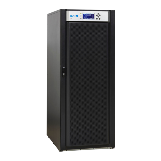
List of Tables viii Eaton 93E External Battery Cabinet Installation Manual P-164000057—Rev 05... - Page 9 93E 20-30 kVA and 40-60 kVA UPS to enhance the usability and reliability of the systems. The EBC safeguards operation during brownouts, blackouts, and other power interruptions providing cost-effective extended battery run time. Two models are available, the 93E 30EBC and 93E 60EBC and are equipped with valve-regulated lead-acid (VRLA) batteries.
- Page 10 Battery string kits are available to upgrade each 93E 30 EBC from two strings to three strings and each 93E 60 EBC from four strings to six strings. Kits must be installed by an authorized Eaton Customer Service Engineer. Contact an Eaton sales representative for information.
- Page 11 Introduction Figure 2. Eaton 93E 30 kVA UPS and Two Eaton 93E 30EBCs EBC 1 EBC 2 Eaton 93E External Battery Cabinet Installation Manual P-164000057—Rev 05...
- Page 12 Introduction Figure 3. Eaton 93E 60 kVA UPS and Two Eaton 93E 60EBCs EBC 1 EBC 2 1 1 . . 4 4 U U s s i i n n g g T T h h i i s s M M a a n n u u a a l l This manual describes how to install the EBC and is divided into chapters.
- Page 13 F F o o r r M M o o r r e e I I n n f f o o r r m m a a t t i i o o n n Refer to the Eaton 93E UPS (20-30 kVA, 208/220V) Installation and Operation Manual or Eaton 93E UPS (40-60 kVA, 208/220V) Installation and Operation Manual for the following additional information: •...
- Page 14 E E q q u u i i p p m m e e n n t t R R e e g g i i s s t t r r a a t t i i o o n n Please visit www.eaton.com/pq/register to register your new Eaton UPS / Eaton UPS Accessory. Model Number: Serial Number:...
- Page 15 ELECTRIC ENERGY HAZARD. Do not attempt to alter any UPS or battery wiring or connectors. Attempting to alter wiring can cause injury. • Do not open or mutilate batteries. Released electrolyte is harmful to the skin and eyes. It may be toxic. Eaton 93E External Battery Cabinet Installation Manual P-164000057—Rev 05...
-
Page 16: Safety Warnings
Ne pas fumer près des accumulateurs. Ne pas produire de flamme ou d’étincelle dans la zone de l’accumulateur. Dissiper l'électricité statique de votre corps en touchant une surface reliée à la terre avant de toucher les accumulateurs. Eaton 93E External Battery Cabinet Installation Manual P-164000057—Rev 05... - Page 17 If the UPS system is to be operated at an altitude higher than 1500m (5000 ft), contact an Eaton service representative for important information about high altitude operation. The operating environment must meet the weight, clearance, and environmental requirements specified for the applicable accessory cabinet.
-
Page 18: Installation Plan And Unpacking
Operating temperatures above the recommended range will result in decreased battery life and performance, and will reduce or void the battery warranty. Refer to Eaton's Terms and Conditions of Sale with Battery Replacement Coverage and the Battery Replacement Price Book for more information. These documents can be found at www.eaton.com/powerquality... - Page 19 Installation Plan and Unpacking Figure 4. 93E 30EBC Cabinet Dimensions (Front, Right Side, and Rear Views) Front View Side View Rear View Dimensions are in millimeters [inches] Eaton 93E External Battery Cabinet Installation Manual P-164000057—Rev 05...
- Page 20 Installation Plan and Unpacking Figure 5. 93E 30EBC Dimensions (Top and Bottom Views) Bottom View Top View Dimensions are in millimeters [inches] Eaton 93E External Battery Cabinet Installation Manual P-164000057—Rev 05...
- Page 21 Dimensions are in millimeters [inches] Center of Gravity, see Figure 6 EBC with 2 strings 504 (20.0) 430 (17.0) 228 (9.0) EBC with 3 strings 665 (26.2) 430 (17.0) 224 (8.8) Eaton 93E External Battery Cabinet Installation Manual P-164000057—Rev 05...
- Page 22 Installation Plan and Unpacking Figure 7. 93E 60EBC Cabinet Dimensions (Front, Right Side, and Rear Views) Front View Side View Rear View Dimensions are in millimeters [inches] Eaton 93E External Battery Cabinet Installation Manual P-164000057—Rev 05...
- Page 23 Installation Plan and Unpacking Figure 8. 93E 60EBC Dimensions (Top and Bottom Views) Bottom View Top View Dimensions are in millimeters [inches] Eaton 93E External Battery Cabinet Installation Manual P-164000057—Rev 05...
- Page 24 Dimensions are in millimeters [inches] Center of Gravity, see Figure 9 EBC with 4 strings 690 (27.2) 406 (16.0) 392 (15.4) EBC with 6 strings 865 (34.1) 406 (16.0) 392 (15.4) Eaton 93E External Battery Cabinet Installation Manual P-164000057—Rev 05...
- Page 25 External battery cabinets can be used in combination with a UPS containing internal batteries. • Internal battery strings are to be connected by an authorized Eaton Customer Service Engineer. • Refer to the appropriate Eaton 93E UPS Installation and Operation manual listed in paragraph 1.7 For More Information...
- Page 26 Use of any other battery type or mixing battery letter designation and sizes inside Eaton cabinets will damage equipment and void the product warranty. When replacing batteries use the same manufacturer and part number originally supplied with the unit to ensure correct harness fit and terminal landing.
- Page 27 Carefully inspect the outer packaging for evidence of damage during transit. CAUTION Do not install a damaged cabinet. Report any damage to the carrier and contact an Eaton service representative immediately. NOTE For the following step, verify that the forklift or pallet jack is rated to handle the weight...
- Page 28 B B a a t t t t e e r r y y B B r r e e a a k k e e r r L L o o c c a a t t i i o o n n Figure 11 shows the location of the battery breakers in the 93E 30EBC and the 93E 60EBC. Eaton 93E External Battery Cabinet Installation Manual P-164000057—Rev 05...
- Page 29 Installation Plan and Unpacking Figure 11. Eaton 93E 30EBC and Eaton 93E 60EBC Battery Breaker Locations – Front Views with Doors Removed Battery Breaker Battery Breaker 93E 30EBC 93E 60EBC Eaton 93E External Battery Cabinet Installation Manual P-164000057—Rev 05...
- Page 30 Installation Plan and Unpacking Eaton 93E External Battery Cabinet Installation Manual P-164000057—Rev 05...
- Page 31 Insert the forklift or pallet jack forks between the supports on the bottom of the pallet (see Figure 6 for the EBC cabinet center of gravity measurements). Eaton 93E External Battery Cabinet Installation Manual P-164000057—Rev 05...
-
Page 32: Installation
(counterclockwise) and swing the door open. If the leveling feet are not fully retracted, turn all four leveling feet until they are retracted into the cabinet. Figure 12. Removing the Front Shipping Bracket – 93E 30EBC Front Door Pallet Extension Plate... - Page 33 10. Use a forklift or pallet jack between the supports on the bottom of the pallet to lift the pallet by approximately 3 mm (1/8") and remove the skid (see Figure 13). Figure 13. Removing the Rear Shipping Bracket – 93E 30EBC Skid Bolts (3 places) Removable Skid Shipping Bracket...
- Page 34 11. Slowly roll the cabinet toward the rear of the pallet. Once the pallet tilts, continue rolling the cabinet down the pallet until the cabinet is clear of the pallet. Figure 14. Installing the Pallet Extension Plate – 93E 30EBC Pallet Extension Plate (installed for unloading) 12.
- Page 35 CABINET MAY FALL. Do not loosen the hardware attaching the front supports to the cabinet base. The cabinet must be lowered by the jacking bolts before the supports can be removed. Eaton 93E External Battery Cabinet Installation Manual P-164000057—Rev 05...
- Page 36 Step 1 through Step 18; otherwise, proceed to Step 20. Install the second EBC on the right side of the first EBC. 20. Proceed to paragraph 4.3 Installing Power Terminal Cover Base. Eaton 93E External Battery Cabinet Installation Manual P-164000057—Rev 05...
- Page 37 Wiring can be installed using conduit between cabinets or by routing wiring through the power terminal cover base wiring channels. To install the Power Terminal Cover Base: Locate the terminal cover base (see Figure 16) from the parts kit. Eaton 93E External Battery Cabinet Installation Manual P-164000057—Rev 05...
- Page 38 Figure 16. EBC Power Terminal Cover Parts Right Side Left Side Base Wire Hooks Conduit Landing for DC Input and Output when using conduit (Install conduit to bottom of base.) Base (Inside View) Eaton 93E External Battery Cabinet Installation Manual P-164000057—Rev 05...
- Page 39 Punch or drill holes in the bottom of the power terminal cover base on the UPS cabinet for the DC input conduit. Refer to the applicable Eaton 93E UPS Installation and Operation manual listed in paragraph 1.7 For More Information for UPS cabinet conduit landing location.
- Page 40 Figure Route the other end of the battery cables (positive, negative, and ground) to the UPS cabinet external battery input and ground terminals. Refer to the applicable Eaton 93E UPS Installation and Operation manual listed in paragraph 1.7 For More Information for UPS cabinet terminal locations and termination requirements.
- Page 41 Internal battery strings are to be connected by an authorized Eaton Customer Service Engineer at system startup. 31. Once the battery cabinets are installed and wired, return to the applicable Eaton 93E UPS Installation and Operation manual listed in paragraph 1.7 For More Information...
- Page 42 Installation Figure 18. DC Power Terminal Locations – 93E 30EBC Ground Terminals DC Input and Output Terminals + and – Eaton 93E External Battery Cabinet Installation Manual P-164000057—Rev 05...
- Page 43 Installation Figure 19. DC Power Terminal Detail – 93E 30EBC Ground Terminals UPS DC (+) DC In (+) (DC output to UPS or EBC 1.) (DC input from EBC 2.) UPS DC (–) DC In (–) (DC output to UPS or EBC 2.) (DC input from EBC 2.)
- Page 44 Installation Figure 20. DC Power Terminal Locations – 93E 60EBC Ground Terminals DC Input and Output Terminals + and – Eaton 93E External Battery Cabinet Installation Manual P-164000057—Rev 05...
- Page 45 DC In (+) (DC output to UPS or EBC 1.) (DC input from EBC 2.) UPS DC (–) DC In (–) (DC output to UPS or EBC 2.) (DC input from EBC 2.) Eaton 93E External Battery Cabinet Installation Manual P-164000057—Rev 05...
- Page 46 Base Wiring Channel 93E 30EBC 93E 30 kVA UPS NOTE The 93E 30EBC and 93E 30 kVA UPS are shown. However, the 93E 60EBC and 93E 60 kVA UPS installation is the identical. Eaton 93E External Battery Cabinet Installation Manual P-164000057—Rev 05...
- Page 47 Top Installed 93E 30EBC NOTE 1 The 93E 30EBC is shown. However, the 93E 60EBC installation is identical. NOTE 2 Do not install the Power Terminal Cover Left and/or Right Side covers if wiring adjacent cabinets using the power terminal base wiring channel.
- Page 48 93E 30EBC 93E 30 kVA UPS NOTE 1 The 93E 30EBC and 93E 30 kVA UPS are shown. However, the 93E 60EBC and 93E 60 kVA UPS installation is identical NOTE 2 Do not install the Power Terminal Cover Left and/or Right Side covers if wiring adjacent cabinets using the power terminal base wiring channel.
- Page 49 Make a copy of the Installation Checklist before filling it out, and retain the original. After the installation is complete, an Eaton Customer Service Engineer must verify the operation of the UPS system and commission it to support the critical load. The service representative cannot perform any installation tasks other than verifying software and operating setup parameters.
- Page 50 Installation Notes _________________________________________________________________________ _________________________________________________________________________ _________________________________________________________________________ _________________________________________________________________________ _________________________________________________________________________ _________________________________________________________________________ _________________________________________________________________________ _________________________________________________________________________ _________________________________________________________________________ _________________________________________________________________________ _________________________________________________________________________ _________________________________________________________________________ _________________________________________________________________________ _________________________________________________________________________ _________________________________________________________________________ Eaton 93E External Battery Cabinet Installation Manual P-164000057—Rev 05...
- Page 51 S S c c h h e e m m a a t t i i c c s s Figure 27 Figure 28 show the 93E 30 EBC and 93E 60 EBC schematics. Eaton 93E External Battery Cabinet Installation Manual P-164000057—Rev 05...
- Page 52 DC IN From EBC 2 UPS DC terminals (if applicable) From UPS or (if applicable) EBC 2 ground To EBC 2 ground (if applicable) LEGEND Factory Wiring Customer Wiring Half Battery String Eaton 93E External Battery Cabinet Installation Manual P-164000057—Rev 05...
- Page 53 DC IN From EBC 2 UPS DC terminals(if applicable) From UPS or (if applicable) EBC 2 ground To EBC 2 ground (if applicable) LEGEND Factory Wiring Customer Wiring Half Battery String Eaton 93E External Battery Cabinet Installation Manual P-164000057—Rev 05...
- Page 54 Onelines and Schematics Eaton 93E External Battery Cabinet Installation Manual P-164000057—Rev 05...
- Page 55 6 6 . . 2 2 . . 3 3 A A N N N N U U A A L L M M a a i i n n t t e e n n a a n n c c e e Annual preventive maintenance should be performed only by authorized service personnel familiar with maintenance and servicing of the UPS system. Contact an Eaton service representative for more information about service offerings.
-
Page 56: Maintenance
Phillips and Pozidriv are registered trademarks of Phillips Screw Company. A basic training course, available from Eaton, gives you a competent working knowledge of the UPS system Copyright 2008–2010 Eaton Corporation, Raleigh, NC, USA. All rights reserved. No part of this document may be reproduced in any way without the express written approval of Eaton Corporation. - Page 57 M M o o d d e e l l N N u u m m b b e e r r s s The External Battery Cabinet (EBC) is available in two models to meet the needs of the Eaton 93E UPS product line.
-
Page 58: Product Specifications
Relative Humidity (operating and storage) Acoustical Noise Not applicable Safety Conformance UL1778 5 edition, UL60950-1 1 edition Agency Markings cULus FCC Part 15 Class A and 62040-2 c3 EMC (Class A) Eaton 93E External Battery Cabinet Installation Manual P-164000057—Rev 05... -
Page 59: Equipment Registration
C C h h a a p p t t e e r r 8 8 W W a a r r r r a a n n t t y y For warranty information, please refer to the Resources link on our website, www.eaton.com/93E. - Page 60 P-16400005705 P-164000057 05...
Need help?
Do you have a question about the 93E 30EBC and is the answer not in the manual?
Questions and answers