
Related Manuals for Eaton MTL 9493-PS-XXX


Summary of Contents for Eaton MTL 9493-PS-XXX
- Page 1 Instruction manual February 2016 MTL intrinsic safety solutions INM MTL 9493-PS-XXX rev 1 MTL 9493-PS-XXX intrinsically safe power supply...
- Page 2 This page left intentionally blank INM 9493-PS-XXX rev 1...
-
Page 3: Table Of Contents
4 .7 Fitting MTL 9493-PS-XXX modules to backplane . . . . . . . . . . . . . . . . - Page 4 No changes to any of the components that might impair their explosion protection are permitted. If any information provided here is not clear: Contact Eaton or an authorised MTL distributor or sales office. NOTE Improper installation and operation of the enclosure can result in the invalidation of the guarantee .
-
Page 5: Features
The MTL 9493-PS-XXX Power Supply is a general purpose intrinsically safe power supply unit. It takes a 24v DC safe area or zone 2 supply and produces an intrinsically safe output available in a range of different DC voltages. The MTL 9493-PS-XXX may be mounted in a safe area or zone 2 hazardous area. -
Page 6: Din-Rail Installation Method
24VDC input connection to the modules, or alternatively a number of them can be DIN-rail mounted with a convenient “Powerbus” input. The MTL 9493-PS-XXX module has LED power indication for both input and output (see Figure 2.2) along with internal current limiting and electronic auto-reset circuit breaker action to protect the module in the event of its output being short circuited or overloaded. -
Page 7: Protection Of Equipment
This section deals with mounting the individual MTL 9493-PS-XXX power supplies on DIN rail, for backplane mounting see Section 4. WARNING ! If this module is to be connected to intrinsically safe apparatus, it must be installed, operated and maintained only be trained competent personnel and in accordance with all appropriate international, national and local standard codes of practice and site regulation and in accordance with the instructions contained here. -
Page 8: Mounting Power Supplies On Din Rail
3 .2 . 1 Mounting power supplies on DIN rail Clip power supplies onto type T35 DIN rail as shown in Figure 3.2, with the blue signal plugs facing towards the hazardous-area wiring. To remove an power supply from the rail, insert a screwdriver blade into the clip as shown and lever the clip gently outwards;... -
Page 9: Ambient Temperature Considerations
Finishing Wire up individual power supplies in accordance with wiring schedules. Daisy-chain power supply connections between individual power plugs or use the power bus (see section 4.1). Segregate hazardous- and safe-area wiring into separate trunking or looms wherever possible to avoid errors and maintain a tidy installation. -
Page 10: Earth Rail And Tagging Accessories
Spares replacement, for use with TAG57 tagging strip. MS010 DIN rail module spacer, 10mm, pack of 5 (figure 3 .8) Grey spacer; one required between each MTL 9493-PS-XXX and any adjacent module on a DIN rail, to provide 10mm air-circulation space between modules. ETM7 Earth terminal, bag of 50 (figure 3 .9) - Page 11 THR2 TGL57 ERB57S IMB57 TAG57 Snap off extension when using IMB57 as central support ERB57 10mm Earth 14mm clamp Earth-rail clamp ETM7 Push ERL7 fastener ERB57S in upper ERB570 position ERB57S in lower ERL7 position IMB57 ETM7 TGL57 HAZ1-3 HAZ4-6 TAG57 Figure 3 .4: Assembly drawing showing part numbers Figure 3 .5: Mounting details...
-
Page 12: Assembly
3 .5 Assembly 3 .5 . 1 Fitting earth rails a) In upper position Before fitting insulating mounting blocks IMB57 , check that the swing nuts in the base of each unit are turned back into the moulding. Locate the mounting blocks on the DIN rail in the chosen position and tighten the screws (see figure 3.11). -
Page 13: Completed Assemblies
3 .5 .3 Completed assemblies Figure 3.12 illustrates a complete assembly of MTL 9493-PS-XXX power supplies using the accessories mentioned above. The broken-line boxes either side of the assembly represent cable trunking, and the accompanying dimensions represent the minimum spacing between trunking and assemblies. -
Page 14: Backplane Mounting Variant
See the table for details of the kits and accessories applicable to the mounting methods and Figure 4.1 for dimensions and mounting centres. Note: Before mounting a MTL 9493-PS-XXX on a backplane two minor modifications must be made. Remove the DIN-rail mounting clip by compressing the small spring inside the clip with a screwdriver and then removing it;... - Page 15 M4 x 20mm Fixing Screws screw(1) G-section G-section T-section Locking washer (2) T-section End stop (13) (12) (13) (12) MTL4500 (11) Plain washer (3) backplane Mounting hole A M4 x 10mm spacer(5) Retaining Washer (6) Figure 4 .2: Surface mounting procedure Figure 4 .5: Mounting end stops onto DIN rail Centre A Centre A...
-
Page 16: Surface Mounting - With Kit Sms01
4 .3 . 1 Surface mounting – with kit SMS01 See Figures 4.1 and 4.2. Select four M4 x 20mm screws. Prepare holes in the surface at centres A, tapping these if retaining nuts are not required (Figure 4.1). Place a locking washer (2) and a plain washer (3) over each M4 x 20mm screw (1) (Figure 4.2). - Page 17 Tagging strip Retaining PWR1 PWR2 – tie (7) Primary Secondary Power Power Supply Supply SKT 1 SKT 2 0V PWR1 0V PWR2 Figure 4 .11: Power supply connections Figure 4 .8: Attaching and swivelling a tagging-strip P W R 1 Plastic rivet (7) Earth rail (5) Earth rail...
-
Page 18: Backplanes - Earth Rails
(14 AWG) can be used and should be chosen according to load and voltage drop. 4 .7 Fitting MTL 9493-PS-XXX modules to backplane WARNING ! When installing MTL 9492-PS-PLUS power supply modules it is essential to make sure that intrinsically safe and non-intrinsically safe wiring is segregated as required by a nationally accepted authority or as described in BS EN 60079-14, ISA RP 12.6 or DIN VDE-165. - Page 19 Figure 4 .15: Fitting power supplies to backplane Hazardous area power connectors Haz 1-3 ia output 0ther models available Figure 4 .14: Key elements of the MTL 9493-PS-XXX power supply Figure 4 .16: Removing power supplies from backplane INM 9493-PS-XXX rev 1...
-
Page 20: Environmental
ENVIRONMENTAL Operating Temperature -40°C…+70°C Storage Temperature –40°C…+70°C Humidity 5…95% RH, non condensing WASTE REMOVAL INFORMATION The electronic equipment within must not be treated as general waste. By ensuring that this product is disposed of correctly you will be helping to prevent potentially negative consequences for the environment and human health, which could otherwise be caused by incorrect waste handling of this product. - Page 21 The following information is in accordance with the Essential Health and Safety Requirements (Annex II) of the EU Directive 94/9/EC [the ATEX Directive - safety of apparatus] and is provided for those locations where the ATEX Directive is applicable. General This equipment must only be installed, operated and maintained by competent personnel.
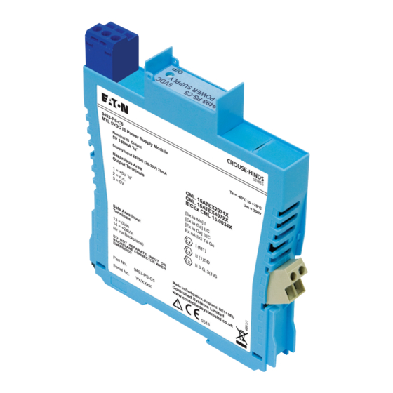
- Page 22 Each device is marked in accordance with the Directive and CE marked with the Notified Body Identification Number. This information applies to products manufactured during or after the year 2010. Figure 8 .1 MTL 9493-PS-XXX product label INM 9493-PS-XXX rev 1...
-
Page 23: Declaration Of Conformity
APPENDIX A - DECLARATION OF CONFORMITY INM 9493-PS-XXX rev 1... - Page 24 DECLARATION OF CONFORMITY - continued INM 9493-PS-XXX rev 1...
- Page 25 This page left intentionally blank INM 9493-PS-XXX rev 1...
- Page 26 This page left intentionally blank INM 9493-PS-XXX rev 1...
- Page 27 This page left intentionally blank INM 9493-PS-XXX rev 1...
- Page 28 MTL Instruments GmbH, Heinrich-Hertz-Str. 12, 50170 Kerpen, Germany UNITED ARAB EMIRATES Cooper Industries/Eaton Corporation Tel: +49 (0)22 73 98 12 - 0 Fax: +49 (0)22 73 98 12 - 2 00 Office 205/206, 2nd Floor SJ Towers, off. Old Airport Road, E-mail: mtlgmbh@eaton.com...
Need help?
Do you have a question about the MTL 9493-PS-XXX and is the answer not in the manual?
Questions and answers