Table of Contents
Advertisement
Quick Links
WARNINGS & CAUTIONS:
• TO AVOID FIRE, SHOCK, OR DEATH; TURN OFF POWER at circuit breaker or fuse and test that the power
is off before wiring or servicing luminaire or changing bulbs!
• TO AVOID FIRE, SHOCK, DEATH, OR DAMAGE TO PROPERTY, DO NOT control a load in excess of the
specified ratings. Check your load ratings to determine the unit's suitability for your application.
• To be installed and/or used in accordance with appropriate electrical codes and regulations.
• If you are not sure about any part of these instructions, consult an electrician.
DESCRIPTION
The OSM3D-DDW is a 5.8 GHz high frequency microwave motion sensor designed to provide additional energy
savings with 0-10V dimming. It will switch luminaire ON when motion is detected and OFF after the set Hold Time
expires when there is no motion detected.
A built-in Daylight Sensor reads brightness value, so that the sensor will not switch the luminaire ON if there is
sufficient ambient light present. Add a Leviton
achieve daylight harvesting.
The sensor uses microwave technology (similar to ultrasonic technology). Microwaves are extremely sensitive,
omni-directional and will penetrate through most building construction materials. Microwaves do not pass through
metal and is the one material used to control the direction of the microwave detection.
FEATURES
• Automatic switching or dimming when used in combination with 0-10V dimmable LED drivers or ballasts.
• Built-in Daylight Sensor.
• 0-10V interface can be linked to a Leviton low voltage photocell (ODC0P-D0W sold separately) to achieve
daylight harvesting.
• 5.8 GHz high frequency microwave detection technology.
• Compact size makes it suitable to fit within most luminaires.
• 7-position terminal block, easy assembly.
• 2 types of installation, base mounting and flush mounting, suitable for different luminaires.
• Detection Area, Hold Time and Daylight Sensor can be precisely set via DIP switches.
• Supports higher mounting height up to 40' (12 m) max.
• Wide Detection Area, range up to 52' (16 m) in diameter.
• 5 year warranty.
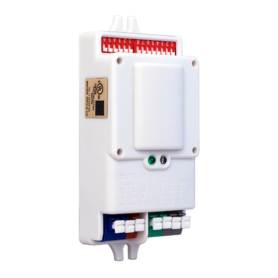
Fig. 1
Work Light (Green LED ON)
0-10V
SYNC
OUTPUT
INPUT
Mounting Hole
FUNCTIONS
ON/OFF (Wiring diagram 1): The sensor will switch lights ON when motion is detected, and OFF after the set Hold
Time has expired when no motion is detected. A built-in Daylight Sensor reads brightness value in the area, so
that the sensor will not switch the lights ON if there is sufficient natural light present. The threshold can be adjusted
from 100 lux to 50 lux, 25 lux, 10 lux, 5 lux and 2 lux.
• When sufficient ambient light is present, the sensor does not switch ON the luminaire.
• When there is insufficient ambient light, the sensor switches ON the luminaire when motion is detected.
• After the set Hold Time, the sensor switches OFF the luminaire when no motion is detected.
3-Step Dimming (Wiring diagram 2): 0-10V luminaire are controlled by several sensors tied together through the
SYNC connection. When motion is detected by any one of the sensors a signal is transmitted to the other sensors.
Then, all luminaires switch ON at the same time.
• When motion is detected from any direction, all luminaires switch ON at the same time.
• When no motion is detected in the Detection Area, all luminaires dim to the set Stand-by Dim Level at the
same time after the set Hold Time expires.
• After the Stand-by Period, the luminaires switch OFF if no motion is detected in the Detection Area.
• When no motion is detected, all luminaires switch OFF.
Daylight Harvesting (Wiring diagram 3): When used in combination with an 0-10V external Daylight Sensor
(ODC0P-D0W sold separately), the system has automated controls that either turn OFF or DIM artificial light in
response to the available daylight in the space.
NOTE: The preset illumination level is set at the 0-10V external Daylight Sensor.
• When ambient is light greater than the preset illumination level, the luminaire does not switch ON.
• When ambient is light less than the preset illumination level, the luminaire switches ON when motion is detected.
• The luminaires switch ON to 100% or DIM to maintain the preset illumination level against the level of ambient light.
• When sufficient ambient light is present the luminaire switches OFF, even if motion is detected.
• When there is insufficient ambient light, the luminaires DIM to the Stand-by Dim Level when no motion is
detected after the Hold Time expires, and then switches OFF after the Stand-by Period.
NOTE: The Stand-by Dim Level is set at the motion sensor.
DETECTION AREA
The coverage area, or field of view, of the OSM3D-DDW is designed to cover a 32 ft. (10 M) radius space when
mounted at a typical 40 ft. (12 M) above the floor. This monitored space is in the form of a cone radiating from the
center of the sensor.
Ceiling Pattern
(10-40 ft. [3-12 m] height)
75%
50%
25%
10%
8
6
4
2
2
4
(Units: m)
© 2017 Leviton Mfg. Co., Inc.
High Frequency Microwave Sensor 0-10V Dim
400W @ 120VAC - Tungsten
Operating Temperature: -35°C to 70°C
INSTALLATION INSTRUCTIONS
®
0-10V external Daylight Sensor (ODC0P-D0W sold separately) to
Daylight Sensor
Antenna Module
DIP Switch, Bank 2
(DIP switch # 1-6)
Wall Pattern
(3- 6 ft. [1-1.8 m] height)
18
16
14
12
10
8
100%
6
100%
75%
4
50%
2
10%
6
8
2
4
6
8
10
12
2
4
6
8
10
12
14
16
18
For Technical Assistance Call: 1-800-824-3005 (U.S. Only) www.leviton.com
Cat. No. OSM3D-DDW
800W @ 120VAC - Driver/Ballast
1000W @ 277VAC - Driver/Ballast
Relative Humidity: 20% to 90% non-condensing
Rating: 120-277VAC 50Hz/60Hz
WARNINGS & CAUTIONS:
• DO NOT attempt to disable or repair.
• Use this device with COPPER OR COPPER CLAD WIRE ONLY.
NOTE:
• Microwaves cannot pass through metal or brick walls if thicker than 7.75 in. (20 cm). They will pass through
thinner walls but there will be some attenuation.
INSTALLATION
INSTALLATION
1. WARNING: TO AVOID FIRE, SHOCK, OR DEATH; TURN OFF POWER at circuit breaker or fuse and test that
the power is off before wiring or servicing luminaire or changing bulbs!
2. Mount in a listed junction box or enclosure only. There are two types of installation, base-mounting (fig. 2) and
flush-mounting (fig. 3), suitable for different luminaire. Mounting hardware is not provided.
3. Connect wires per appropriate Wiring Diagram as follows:
- INPUT: Strip wires approx. 3/8" (.95 cm) and insert into push-in-terminals.
Line Hot wire to INPUT terminal marked L; Line Neutral wire to INPUT terminal marked N.
- OUTPUT: Strip wires approx. 3/8" (.95 cm) and insert into push-in-terminals.
Load Hot wire to OUTPUT terminal marked L; Load Neutral wire to OUTPUT terminal marked N.
- 0-10V: Strip wires approx. 3/8" (.95 cm) and insert into push-in-terminals.
0-10V + (Violet) wire to 0-10V terminal marked +; 0-10V - (Gray) wire to 0-10V terminal marked -.
- SYNC: Strip wires approx. 3/8" (.95 cm) and insert into push-in-terminals. SYNC terminal/wire connects
multiple sensors together for the 3-step dimming and daylight harvesting functions.
NOTE: Push-in-terminals accept #22-#16 AWG wire.
4. Restore power at circuit breaker or fuse.
NOTE: Allow approximately two minutes for charge-up. If the lights turn ON and the LED blinks when a hand
is waved in front of the sensor, then the unit was installed properly. If the operation is different, refer to the
Troubleshooting Section. The Sensor is factory preset to work without any adjustments.
Fig. 2 (Base mounting)
Enclosure
NOTE: Mounting hardware not provided.
SETTINGS
DIP Switch, Bank 1
Detection Area, Hold Time, Stand-by Period, Daylight Sensor and Stand-by Dim Level can be set by using DIP
(DIP switch # 1-8)
switches on the sensor.
NOTE: Reducing the Detection Area will also reduce the sensitivity. Adjust the DIP switches as needed for your
specific application.
Mounting Hole
Fig. 4
ON
1
2
ON
ON
ON
-
-
ON
-
-
Fig. 5
ON
3
4
ON
ON
-
ON
ON
-
-
-
ON
ON
-
-
Fig. 6
ON
6
7
ON
ON
-
ON
ON
-
-
-
-
ON
-
-
Fig. 7
ON
1
2
-
-
-
-
-
ON
-
-
-
ON
ON
-
-
-
Fig. 8
ON
5
6
ON
ON
-
ON
ON
-
-
-
TROUBLESHOOTING
• Lights will not turn ON
- Sensor is wired incorrectly, confirm that the sensor's wiring is done correctly and inspect visually for problems.
- Incorrect Daylight Sensor setting selected, adjust setting.
14
16
18
• Lights will not turn OFF
- Sensor is wired incorrectly, confirm that the sensor's wiring is done correctly and inspect visually for problems.
- Make sure the luminaire is installed with at least 1 ft. (30 cm) of space between the luminaire and surrounding
reflective surfaces, i.e. metal, glass or concrete walls.
- Detection Area set improperly, adjust DIP switches #1-2, Bank 1.
• Lights turn OFF and ON too quickly
- Detection Area set improperly, adjust DIP switches #1-2, Bank 1.
- Hold Time set improperly, adjust DIP switches #3-5, Bank 1.
(Units: m)
Fig. 3 (Flush mounting)
NOTE: Antenna opening dimensions
0.98 in. x 1.38 in. (2.48 cm x 3.50 cm)
Sensor
Enclosure
Mounting Screws (x2)
Detection Area: DIP Switches #1-2, Bank 1
The sensitivity can be reduced from 100% to 75%, 50% or 10% by
100%
selecting the correct combination of DIP switch settings shown (fig. 4).
75%
50%
10%
Hold Time: DIP Switches #3-5, Bank 1
5
ON
5s
The amount of time the luminaire remain at 100% after no motion is
detected. The time can be adjusted from 5s to 5min, 10min, 20min, 30min,
ON
5min
and + by selecting the correct combination of DIP switch settings
ON
10min
shown (fig. 5).
ON
20min
NOTE: When set to + the sensor function will be inactive.
-
30min
-
+
Stand-by Period: DIP Switches #6-8, Bank 1
8
ON
0s
The amount of time the luminaire remains at the Stand-by Dim Level
before completely switching OFF in the absence of motion. The time
ON
5s
can be adjusted from 1hr to 30min, 10min, 5min, 5s, 0s and + by
ON
5min
selecting the correct combination of DIP switch settings shown (fig. 6).
ON
10min
NOTE: When set to 0s the luminaire switch ON/OFF only.
-
1hr
NOTE: When set to + the Stand-by Dim Level will be maintained
-
+
until motion is detected.
Daylight Sensor: DIP Switches #1-4, Bank 2
3
4
ON
ON
2 lux
The sensor can be set to only allow the luminaire to illuminate below a
defined ambient brightness threshold. The threshold can be adjusted
-
ON
5 lux
from 100 lux to 50 lux, 25 lux, 10 lux, 5 lux, and 2 lux. When set to
ON
-
10 lux
Disable, the Daylight Sensor will switch ON the luminaire when motion
ON
-
25 lux
is detected regardless of the ambient light level (fig. 7).
-
-
50 lux
NOTE: The Daylight Sensor is only active when the luminaire is
-
-
100 lux
completely switched OFF.
-
-
Disable
NOTE: This option should be set to Disable if a 0-10V external
Daylight Sensor (ODC0P-D0W sold separately) is used.
Stand-by Dim Level: DIP Switches #5-6, Bank 2
The pre-set dim level the luminaires will switch to when the Hold
50%
Time expires (fig. 8).
30%
20%
10%
DI-001-OSM3D-05A
ENGLISH
Sensor
Mounting
Screws (x4)
DI-001-OSM3D-05A
Advertisement
Table of Contents

Related Manuals for Leviton OSM3D-DDW


Summary of Contents for Leviton OSM3D-DDW
- Page 1 NOTE: This option should be set to Disable if a 0-10V external The coverage area, or field of view, of the OSM3D-DDW is designed to cover a 32 ft. (10 M) radius space when Daylight Sensor (ODC0P-D0W sold separately) is used.
- Page 2 Leviton warrants to the original consumer purchaser and not for the benefit of anyone else that this product at the time of its sale by Leviton is free of defects in materials and workmanship under normal and proper use for five...
Need help?
Do you have a question about the OSM3D-DDW and is the answer not in the manual?
Questions and answers