Advertisement
WARNINGS
• TO AVOID FIRE, SHOCK, OR DEATH: TURN OFF POWER AT CIRCUIT BREAKER OR
FUSE AND TEST THAT POWER IS OFF BEFORE WIRING!
• To be installed and/or used in accordance with appropriate electrical codes and regulations.
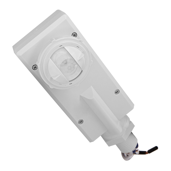
Product Description
The Leviton Integrated Smart Sensor and Photocell uses Bluetooth™ 5.0 technology for
configuration. It is designed for use with Switching or 0-10V LED Drivers and Fluorescent
Ballasts and uses Passive Infrared (PIR) detection technology to monitor a space for
occupancy using advanced lenses. The specialized lenses provide extended Field-of-View
(FOV) for low-mid bay and mid-high bay applications.
Leviton's Integrated Smart Sensors combine multiple sensors and technology to provide
lighting control automatically and efficiently. Occupancy sensors turn the lights
ON and keep them ON while the space is occupied and turns them OFF when the space is
vacant, and the delayed-off timer has expired. Photocell detects natural light and dims lighting
up or down as needed for additional energy efficiency and occupant comfort benefits. The
sensor continually analyzes and adjusts to ensure adequate lighting under
varying conditions.
For Optimal Performance:
The OFD1Z sensor lenses establish dozens of zones of detection. The sensor is sensitive to
the heat emitted by the human body. In order to trigger the sensor, the source of heat must
move from one zone of detection to another. The device is most effective in sensing motion
across its field-of-view, and less effective sensing motion directly towards or away from
the sensor. Keep this in mind when selecting the installation location. Note that occupancy
sensors respond to rapid changes in temperature, so care should be taken NOT to mount the
device near a climate control source (i.e., radiators, air exchanges, and air conditioners). Hot
or cold drafts will register as body motion to the device and will trigger it if the unit is mounted
too close. It is recommended to mount the occupancy sensor at least 6 ft away from a climate
control source.
Tools Needed:
Parts Included:
• Fixture Sensor (1)
• Wire Stripper
• Cutters
• Low/Mid Bay Lens (1)
• High Bay Lens (1)
• 1-1/4 in. Wrench
• Aisleway Mask Cover (2)
• #1 Philips Screwdriver
• Straight 1/2" Threaded Attachment (installed)
• Drop 1/2" Threaded Attachment (2 pieces)
• Gasket for drop threaded attachment
• Additional screws for drop threaded attachment (2)
• Rubber Washer/Gasket for Threaded Attachment
• Lock Nut for Threaded Attachment
Installation
1.
WARNING:
TO AVOID FIRE, SHOCK, OR DEATH, TURN OFF POWER at circuit breaker or fuse and
test that power is off before wiring!
2.
Prepare and connect wires. Refer to the appropriate wiring diagram.
For 0-10V Control Wiring: Connect the VIOLET wire to the 0-10V DIM (+) terminal and
the GRAY or PINK wire to the 0-10V DIM (-) terminal using Class 1 or Class 2 wiring
methods as indicated in these instructions, ballast/fixture/driver instructions, or ballast/
fixture/driver label markings. Observe all requirements of any authority having jurisdiction
with respect to wire type, sleeving, isolation methods, and the like.
3.
Install the sensor.
a. The sensor is designed to be installed through a standard 1/2" knockout.
b. Place gasket on threaded nipple before feeding wires through fixture knockout.
c. Use lock nut to secure sensor to fixture body or junction box. Lock nut should be
tightened to 8-15 lb-in to compress the gasket/washer.
d. Install lens by lining up the mark on the lens 45
the sensor and rotating it 45
°
clockwise to lock it in place.
e. Install optional mask (if required) by aligning the marks on the lens and mask and
rotating the mask.
f. Restore power at circuit breaker or fuse.
NOTES:
• Allow approximately 30 seconds for start-up. If the lights turn ON and the LED blinks BLUE/
GREEN to indicate Daylight Harvesting Calibration has started, then the sensor was
installed properly. If the operation is different, refer to the Troubleshooting section.
• The sensor is preset to work without any adjustments. If you would like to change the factory
settings, refer to the Configuration section.
Wiring Diagram
NEUTRAL
LINE
BLK
WHT
BLU
VIO
PNK/GRY
Integrated Smart Sensor and Photocell
INSTALLATION INSTRUCTIONS
counterclockwise from the near end of
°
LIGHTING
CIRCUIT
LINE FEED
OFD1Z
LIGHTING
LOAD
Cat. No. OFD1Z
CAUTIONS
For indoor or outdoor applications.
Input Voltage/Frequency
LED, Electronic Ballast, General Use @ 120V
LED, Electronic Ballast, General Use @ 230V
LED, Electronic Ballast, General Use @ 277V
Resistive, Tungsten @ 120V
Resistive, Tungsten @ 230V
Resistive, Tungsten @ 277V
0 -10V Dimming Control
Environmental Rating
Network Connections
Operating Temperature
Storage Temperature
* When installed in an appropriate IP66 rated enclosure/fixture.
Mounting Height
Field of View Lens
(Ft.)
8
15
20
20
30
40
Operation
Occupancy Operation
Occupancy Mode: The Occupancy mode and associated settings are configured using the
Leviton Smart Sensor App. These configuration options define how the sensor responds
to occupancy.
• Occupancy (DEFAULT): In this mode, motion detection by the infrared sensor will turn the
lights ON as well as keep them ON.
• Photocell-Only (Occupancy Disabled): When in Photocell-Only mode, the Occupancy
Sensor is disabled, and the sensor ignores motion. In this mode the lights are ON and the
sensor performs daylighting/daylight harvesting only.
NOTE: The Motion Indicator light will blink RED twice (2x) (once per second) for 2 seconds
each time motion is detected.
Photocell Operation
Daylight Mode: The Daylight mode and associated settings are configured using the Leviton
Smart Sensor App. These configuration options define how the sensor responds to ambient
lighting conditions.
• Ambient Light Hold OFF Mode (Daylighting): This mode is used for ON/OFF applications
to hold lights OFF when ambient light level exceeds a set threshold. When little or no
daylight is available, the sensor will turn ON the load. As daylight contribution increases and
crosses a configured threshold, the sensor will hold the load OFF. If light level drops below
the threshold for the duration of the Daylight Response Time (default 5 minutes), the hold
SPECIFICATIONS
120-277 VAC, 50/60 Hz
Current Consumption
Max
15 mA
Standby
8 mA
Load Ratings
6.7 A
5.0 A
5.0 A
800 W
1150 W
1380 W
Motor @ 120 - 277V
1/3 hp
50 mA MAX (sinking)
Wire Lead Length
26 Inches
IP66* (Type 3R)
Bluetooth 5.0
-40 °F to 167 °F (-40 °C to 75 °C)
-40 °F to 185 °F (-40 °C to 85 °C)
Relative Humidity
0% to 90% RH, Non-Condensing
Purpose of Control
Energy Management Equipment
Pollution Degree
2
Impulse Voltage
4000V
Action Control Type
1
Width: 2.14 in. (54.4 mm)
Length w/ Straight: 6.12 in. (155.4 mm)
Dimensions
Length w/ Drop: 6.63 in. (168.4 mm)
Depth: 1.61 in. (40.9 mm)
FIELD OF VIEW
Major
(Sq. Ft.)
Low Bay
2050
Low Bay
1750
Low Bay
1850
High Bay
2300
High Bay
5300
High Bay
8250
DI-000-OFD1Z-02B
ENGLISH
Minor
(Sq. Ft.)
900
750
350
1050
800
550
Advertisement
Table of Contents

Subscribe to Our Youtube Channel
Related Manuals for Leviton OFD1Z


Summary of Contents for Leviton OFD1Z
- Page 1 Motor @ 120 - 277V 1/3 hp The OFD1Z sensor lenses establish dozens of zones of detection. The sensor is sensitive to the heat emitted by the human body. In order to trigger the sensor, the source of heat must...
- Page 2 Leviton warrants to the original consumer purchaser and not for the benefit of anyone else that this product at the time of its sale by Leviton is free of defects in materials and workmanship under normal and proper use for five years from the purchase date. Leviton’s only obligation is to correct such defects by repair or replacement, at its option. For details visit www.leviton.com or call 1-800-824-3005. This warranty excludes and there is disclaimed liability for labor for removal of this product or reinstallation.
Need help?
Do you have a question about the OFD1Z and is the answer not in the manual?
Questions and answers