Table of Contents
Advertisement
Quick Links
WARNINGS
• TO AVOID FIRE, SHOCK, OR DEATH, TURN OFF POWER at circuit breaker or fuse, and test that power is off before wiring!
• To be installed and/or used in accordance with appropriate electrical codes and regulations.
• If you are unsure about any part of these instructions, consult an electrician.
• For indoor applications only.
• SAVE THESE INSTRUCTIONS.
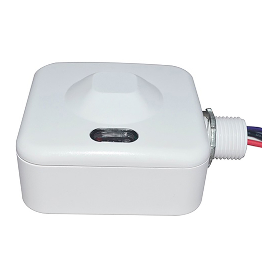
DESCRIPTION
Leviton
®
Cat. No. OSMHB-VDW is a 5.8 GHz high-frequency motion sensor designed to
mount directly to a 0-10V fixture and provide energy savings, with occupancy detection
and multi-level control with adjustable time-outs. A built-in daylight sensor reads brightness
values so that the sensor will not switch the luminaire ON if there is sufficient ambient light
present. Control parameters are manually selected using DIP Switches on the device or
with the ZLS0R-RC1 IR remote (optional) to obtain desired configuration parameters, which
include adjustable Sensitivity, Hold Time, Lux level, Stand-By light level, and Stand-By Hold
Time. The ZLS0R-RC1 IR remote can also be used to store and transmit sensor profiles to
other OSMHB-VDW devices if configuration requirements are the same.
OSMHB-VDW is suited for high bay fixtures. It has a maximum mounting height of up to
50 ft. and an adjustable coverage radius of up to 30 ft.
NOTES:
• Mounts directly to fixture or electrical box.
• Metal can be used to shield or limit field-of-view, if desired.
• Can be used with Leviton offset adapters to improve field-of-view (sold separately).
INSTALLATION PRE-REQUISITES
FOR OPTIMAL PERFORMANCE:
The OSMHB-VDW occupancy sensor detects motion using microwave-sensing technology
(5.8 GHz). Microwave sensors are extremely sensitive, omni-directional, and will penetrate
through most building construction materials. Microwaves, however, will not pass through
metal or brick (if thicker than 7.75 in. [20 cm.]), which can be used to control the direction
of the microwave detection or to shield certain areas from detection, if desired. Microwaves
will pass through thinner walls; however, there will be some reduction of the microwave
strength. Please keep this in mind when determining sensor placement and desired field-
of-view coverage. In order to trigger the sensor, an individual must disrupt the microwave
beam from one zone of detection to another.
CLASS 2 WIRING:
For 0-10V Control Wiring: Connect the Violet wire to the + 0-10V line and the Pink wire
to the 0-10V common, using Class 1 or Class 2 wiring methods, as indicated in these
instructions, ballast/fixture/driver instructions, or ballast/fixture/driver label markings.
Observe all requirements of any authority having jurisdiction with respect to wire type,
sleeving, isolation methods, and the like.
INSTALLATION
WARNING: TO AVOID FIRE, SHOCK, OR DEATH, TURN OFF POWER at circuit breaker
or fuse, and test that power is off before wiring!
1. Position sensor correctly, based on targeted field-of-view.
2. Remove 3/4 in. of insulation from each of the wires and connect per wiring diagram.
3. After all connections have been made, ensure that all wire connectors are firmly
attached and that there is no exposed copper.
4. Adjust sensor operations by using DIP switches on the sensor or optional ZLS0R-RC1
remote. Factory settings default to:
a. Sensitivity: 100%
b. Hold Time: 10 seconds
c. Daylight Sensor: 30 lux
d. Stand-By Level: 30%
e. Stand-By Time: 60 minutes
5. Use the provided plastic nuts and washer to gently mount sensor to its respective fixture
type.
6. Restore power to the circuit and verify that locator LED light is ON.
7. Proceed to device enrollment per the included sheet, and configuration per your system
requirements.
OPERATION
OPERATION
High Bay Microwave Sensor
Cat. Nos. OSMHB-VDW, ZLS0R-RC1
INSTALLATION INSTRUCTIONS
Catalog Numbers
Input Voltage / Frequency
Load Ratings:
• LED, CFL, Electronic Ballast @ 120V
• LED, CFL, Electronic Ballast @ 277V
• Magnetic Ballast @ 120V
• Magnetic Ballast @ 277V
• Resistive, Tungsten @ 120V
• Resistive, Tungsten @ 277V
IP Rating
Network Connections
Operating Temperature
Storage Temperature
Impulse Voltage
Pollution Degree
Action Control Type
Non-Dimming Driver:
Dimming Driver:
Specifications
OSMHB-VDW
120/277VAC, 50-/60Hz
600W
1385W
660W
1200W
800W
1200W
IP20
N/A
-40˚F to 158˚F (-40˚C to 75˚C)
-40˚F to 185˚F (-40˚C to 85˚C)
4000V
2
Type 1
Symbol
~
VAC, Volts Alternating Current
--...
VDC, Volts Direct Current
A
A = Load in Amps
mA
mA = Load in mA
Wiring Diagrams
DI-000-OSMHB-05A
AR2561
ENGLISH
Meaning
Close End Wire Connector
PINK (-)
Advertisement
Table of Contents

Related Manuals for Leviton OSMHD-VDW


Summary of Contents for Leviton OSMHD-VDW
- Page 1 • Mounts directly to fixture or electrical box. • Resistive, Tungsten @ 120V 800W • Metal can be used to shield or limit field-of-view, if desired. • Can be used with Leviton offset adapters to improve field-of-view (sold separately). • Resistive, Tungsten @ 277V 1200W IP Rating...
- Page 2 LIMITED 2 YEAR WARRANTY AND EXCLUSIONS Leviton warrants to the original consumer purchaser and not for the benefit of anyone else that this product at the time of its sale by Leviton is free of defects in materials and workmanship under normal and proper use for two years from the purchase date.
Need help?
Do you have a question about the OSMHD-VDW and is the answer not in the manual?
Questions and answers