Table of Contents
Advertisement
Quick Links
Advertisement
Table of Contents

Subscribe to Our Youtube Channel
Related Manuals for Riken Keiki OHC-800


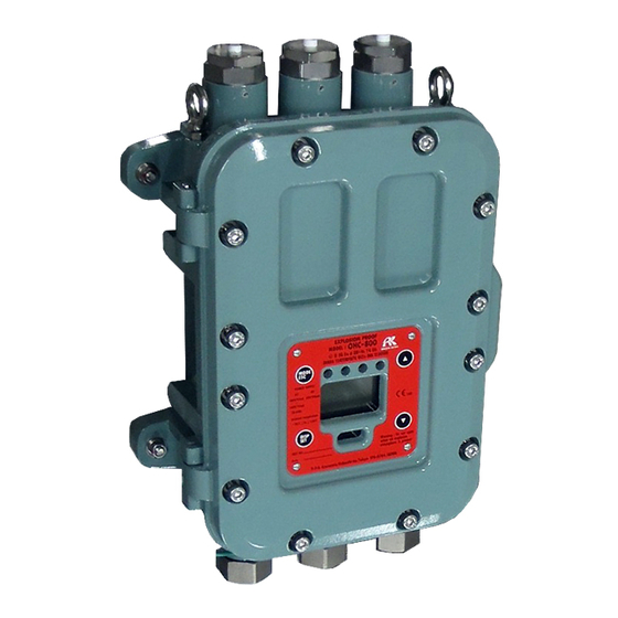
Summary of Contents for Riken Keiki OHC-800
- Page 1 PT3E-04914 Explosion-Proof Calorimeter OHC-800 Operating Manual...
- Page 2 1 Important Notices on Safety 1-1. Danger cases Thank you for choosing our explosion-proof calorimeter OHC-800. This manual explains how to use the calorimeter and its specifications. It contains information required for using the calorimeter properly. Not only the first-time users but also the users who have already used the product must read and understand the operating manual to enhance the knowledge and experience before using the calorimeter.
-
Page 3: Table Of Contents
1-4. Method of confirmation for Standards and Explosion proof specification ............7 1-5. Information about explosion-proof performance (Japanese explosion-proof spec.) ......... 8 1-5-1. About OHC-800 ............................8 1-5-2. Technical data ............................8 1-5-3. System configuration for use in hazardous location ................9 1-6. - Page 4 1 Important Notices on Safety 1-1. Danger cases 6-2-3. 4 – 20 mA condition settings (4 – 20 mA SETTINGS)................53 6-2-4. 4 – 20 mA output adjustment (4 – 20 mA ADJUSTMENT) ............... 54 6-2-5. 4 – 20 mA output test (4 – 20 mA TEST) ....................55 6-2-6.
-
Page 5: Important Notices On Safety
Contact RIKEN KEIKI for information on readjustment including gas calibration and parts replacement. Do not replace parts at your sole discretion but contact RIKEN KEIKI if the transparent window has a crack or the explosion-proof joint surface is abnormal, or the clamping screw or bolt is changed, lost etc. -
Page 6: Warning Cases
1-2. Warning cases WARNING <About explosion-proof> Do not open the front lid of the OHC-800 if the existence of an explosive atmosphere is suspected. WARNING <Power> Before turning on the calorimeter, always check that the voltage is properly applied. Do not use an unstable power supply because it may cause malfunctions. -
Page 7: Precautions
1 Important Notices on Safety 1-3. Precautions 1-3. Precautions CAUTION Do not use a transceiver near the calorimeter. Radio wave from a transceiver near the calorimeter or its cables may disturb indication reading. If a transceiver is used, it must be used in a place where it disturbs nothing. To restart the calorimeter, wait for five seconds or more before doing it. -
Page 8: Information About Explosion-Proof Performance (Japanese Explosion-Proof Spec.)
(Japanese explosion-proof spec.) 1-5-1. About OHC-800 The OHC-800 is an explosion-proof calorimeter. According to measured calorific values, 4 - 20 mA signals and digital signals are output. The calorimeter is used for the purposes of calorific value recording and device control by conntecting it to a recorder or a programmable controller. -
Page 9: System Configuration For Use In Hazardous Location
1-5-3. System configuration for use in hazardous location The OHC-800 has a flame-proof enclosure (Explosion-proof class: Ex dⅡB+H2 T4) and can be used in a Class 1 location. However, if the power source and display instrument etc. connected to it do not have an explosion-proof structure, install it in a non-hazardous area. -
Page 10: Information About Explosion-Proof Performance (Overseas Explosion-Proof Spec.)
1-6. Information about explosion-proof performance (Overseas explosion-proof spec.) 1-6. Information about explosion-proof performance (Overseas explosion-proof spec.) 1-6-1. About OHC-800 This product is a sample draw type fixed Calorimeter. 2 power inputs, AC and DC, are available on the Calorimeter. 1-6-2. Technical data... -
Page 11: System Configuration For Use In Hazardous Location
1 Important Notices on Safety 1-6. Information about explosion-proof performance (Overseas explosion-proof spec.) 1-6-3. System configuration for use in hazardous location Installation Diagram Hazardous Location Nonhazardous Location CaloriMeter (OHC‐800) AC Power / DC Power N/‐ Indicator etc. Sig+ Sig+ CVVS Cable Sig‐ Sig‐ Indicator etc. CVVS Cable Indicator etc. -
Page 12: Notice On Safety
・In case oxygen presents in the sampling gas which is supplied into OHC-800 and emitted from OHC-800, contents of oxygen should be lower than that normally present in air. ・The sampling gas which is supplied into OHC-800 and emitted from OHC-800 should not be within the explosive limits continuously for long period or frequency. - Page 13 1 Important Notices on Safety 1-6. Information about explosion-proof performance (Overseas explosion-proof spec.) Earth terminal Cable gland 13 / 87...
- Page 14 1 Important Notices on Safety 1-6. Information about explosion-proof performance (Overseas explosion-proof spec.) Please install a cable gland into OHC-800 according to the following figure. Please tighten a bolt of a cable gland at 40N・m or more Special conditions for safe use ・Repair of the flameproof joints is not allowed.
-
Page 15: Product Components
NOTE For information on Opt-Sonic calculation, see Section 10.2, "Principle of this product." Opt-Sonic calculation is a coined word by RIKEN KEIKI. The calorimeter can be used with minimum equipment even under constraint conditions with its high evironmental resistance. -
Page 16: Main Unit And Standard Accessories
2 Product Components 2-2. Main unit and standard accessories 2-2. Main unit and standard accessories <Main unit> (including cable glands) Cable gland <Standard accessories> Operating manual Measuring gas specification sheet Dedicated control key (magnet) Hex key wrench (2 mm and 6 mm, one each) ... -
Page 17: Names Of Internal Product Components
2 Product Components 2-3. Names of internal product components 2-3. Names of internal product components Optical sensor unit Sonic sensor unit Main controller Power terminal unit Name Functions Optical sensor unit Measures the speed of light that travels through the measuring gas by capturing the refractive index. -
Page 18: Names And Functions Of Display
2 Product Components 2-4. Names and functions of display 2-4. Names and functions of display Ⅱ2G Ex dbⅡB+H2 T4 Gb Switches MEASURING MODE to other mode. MODE/ESC key Used to stop processing. Lights up at power-on. POWER lamp (green) ... -
Page 19: How To Install Calorimeter
How to Install Calorimeter 3-1. Precautions on installation site Use the calorimeter in combination with a sampling device specified by RIKEN KEIKI (or an equivalent cubicle). Do not install this product in any of the following locations. (1) Place where the calorimeter is exposed to oil, (2) Place with vibrations chemicals etc. -
Page 20: Installation Procedure And Required Maintenance Space
3 How to Install Calorimeter 3-2. Installation procedure and required maintenance space 3-2. Installation procedure and required maintenance space Install the OHC-800 and the sampling device on the surface of a robust wall or a freestanding rack etc. using bolts. -
Page 21: How To Connect Wire
NOTE ・If you are considering the use of the RS-485 (MODBUS) communication function, contact RIKEN KEIKI. ・The "b" contact (break contact) under de-energized state may be opened momentarily by a physical shock, such as external force. - Page 22 For this reason, the power terminal unit with DC specifications can not be used as it is when SSR output is taken into. In this case, add an external AC relay outside of OHC-800 and change the output from SSR to dry contact.
-
Page 23: Recommended Cables
3 How to Install Calorimeter 3-3. How to connect wire 3-3-2. Recommended cables Connected to Recommended cable Cable overall outer diameter CVV 1.25 mm /3-core Φ10.0 Power (AC) line CVV 2 mm /3-core Φ11.0 CVVS 1.25 mm /2-core Φ10.0 Power (DC) line CVVS 2 mm /2-core Φ11.0... -
Page 24: How To Lead In And Connect Cables
3 How to Install Calorimeter 3-3. How to connect wire 3-3-3. How to lead in and connect cables As shown on the right side of the figure below, attach the parts in the following order: (1) cable gland, (2) clamp washer, (3) washer, (4) rubber seal, and (5) washer to the cable, then connect the cable into lead-in port through the enclosure by attaching an insulated ring terminal to the tip in order to complete the connection to the terminal block. - Page 25 3 How to Install Calorimeter 3-3. How to connect wire The rubber seals, washers, and clamp washers needed for cable connection vary depending on the overall outer diameter of a cable to be used. The table below shows the relationships between the overall outer diameters of cables and inner diameters of parts.
-
Page 26: Protective Grounding
3 How to Install Calorimeter 3-3. How to connect wire 3-3-4. Protective grounding Connect the calorimeter to the ground using the "external grounding terminal" or "No.(7) of the terminal block" shown in the figure below. External grounding terminal WARNING Before turning on the calorimeter, never fail to connect it to the ground. ... -
Page 27: Precautions On Electrical Work
Not only when the power is turned on but also when the calorimeter is restarted due to momentary blackout, note that OHC-800 is switched to a warm-up status for 15 minutes and stops measurement for function check status (See Sections 4.1, "From display just after power-on to measurement start" and 4.4, "Self-diagnostic function"). - Page 28 3 How to Install Calorimeter 3-3. How to connect wire Introducing protective measures against lightning If cables are installed outside the factory/plant, or if internal cables are installed in the same duct as the cables coming from outside the factory/plant, "inductive lightning surge" may be caused by lightning. Because lightning acts as a large emission source while cables act as a receiving antenna, devices connected to the cables may be damaged..
- Page 29 3 How to Install Calorimeter 3-3. How to connect wire Proper use of contact If the contact output of this product is used on a line where large inductive load occurs, the following errors may occur due to counter electromotive force generated at the contact. ...
-
Page 30: How To Tube
Needle valve Adjusts the flow rate of the reference gas or span gas supplied from UNIT-C. Switching valve Selects a gas to be supplied to the OHC-800. UNIT-B Pressure Adjusts the measurement gas supplied from GAS IN to a regulator constant pressure. -
Page 31: Recommended External Tubing System
If the sampling point is on a high-pressure line over 0.9 MPa, decompression must be performed outside the sampling device. Decompression must be performed as close to the sampling point as possible to ensure the quickest possible arrival of the measuring gas at the OHC-800. (Use the direct-insertion type of pressure regulator if possible.) Since the OHC-800 consumes approximately 300 mL/min of measuring gas, which is small, the bypass flow rate must be increased to ensure quicker arrival of the gas. -
Page 32: Precautions On Tubing Work
3 How to Install Calorimeter 3-4. How to tube The table below shows the guideline values for the "setting pressures of external pressure regulator" and "bypass flow rates" corresponding to the "tubing diameters" and "tubing lengths" from the external pressure regulator to GAS IN of the sampling device in the tubing system shown on the previous page. -
Page 33: How To Operate In Measuring Mode
Initial screen WARM UP screen For 15 minutes after power-on, the OHC-800 remains in the "warm-up state." The warm-up state is classified into the "check of functions (FUNCTION CHECK)" category. In the standard setting, the OHC-800 does not perform measurement, and 4 - 20 mA signals are output according to the setting value specified by the user. - Page 34 4 How to Operate in MEASURING MODE 4-1. From display just after power-on to measurement start When warm-up is completed, measurement is started. At the start of measurement, the screen shown below is displayed. Displays measuring Displays one of the result.
-
Page 35: How To Switch Display Screens
4 How to Operate in MEASURING MODE 4-2. How to switch display screens 4-2. How to switch display screens Press the DISP key during measurement to switch the display among "Calorific value," "Density," "WOBBE index," and "Cyclic display." Calorific value display Density display WOBBE index display Cyclic display... -
Page 36: Switching To Other Mode
FACTORY MODE Used for factory adjustment, maintenance, or start-up. This mode is for exclusive use by RIKEN KEIKI and service engineer designated by RIKEN KEIKI, and normally must not be operated by the user. Prompts the user for password input because measurement is stopped in this mode. -
Page 37: Self-Diagnostic Function
4 How to Operate in MEASURING MODE 4-4. Self-diagnostic function 4-4. Self-diagnostic function The OHC-800, having an advanced self-monitoring/diagnostic function compliant with NAMUR NE107 (self-monitoring/diagnostic of field devices), performs real-time self-diagnostic and monitoring for devices classifying the state into four categories shown below. -
Page 38: Operations Of Contacts, Display, And Signal Output After Recovery To Normal State
FAILURE OUT OF SPECIFICATION MAINTENANCE REQUIRED In the standard setting of the OHC-800, the operations of the contacts, LCD display screen, and 4 - 20 mA signal output are as described below. <Contact activation> The contacts are self-latched, and the contact state is maintained after state recovery. To reset the contact state, enter the CHECK MODE and do as described in Section 5.2.13, "Latching reset for display and... -
Page 39: How To Operate In Check Mode
5 How to Operate in Check Mode 5 How to Operate in Check Mode How to Operate in Check Mode The CHECK MODE is used to display or check the operation status or setting conditions of each unit while continuing measurement. In this mode, 4 - 20 mA signals are output as measuring results without stopping measurement. -
Page 40: Menu Items Of Check Mode
5 How to Operate in Check Mode 5-1. Menu items of CHECK MODE 5-1. Menu items of CHECK MODE The menu items that can be selected in CHECK MODE are shown in the table below. Display the state of the Display the state of the Display the state of the Display the measuring... -
Page 41: Items And Details
5 How to Operate in Check Mode 5-2. Items and details 5-2. Items and details In the menu screen of CHECK MODE, select the desired item using the ▲▼ keys and confirm it using the SET key to display the detailed information for the item. This section describes the detailed information displayed for the items. -
Page 42: Check Of Sonic Sensor Unit State (Sonic Sensor Unit Condition)
5 How to Operate in Check Mode 5-2. Items and details 5-2-2. Check of sonic sensor unit state (SONIC SENSOR UNIT CONDITION) This screen displays the program information for the sonic sensor unit, the self-diagnostic results measured inside the unit etc. Displays the program number, SUM number, and serial number. -
Page 43: Check Of Measuring Conditions For Calorific Value (Calorific Value Parameter)
"offset value" to be used for calorimetry. The "offset value" can be changed using the SETUP MODE as described in Section 6.2.7, "Offset (OFFSET ADJUSTMENT)." Contact RIKEN KEIKI if other item settings need to be changed. Unit of calorimetry Calorific value type... -
Page 44: Check Of Pressure Sensor Output (Pressure Sensor Readings)
P (REF): Output of the micro-differential pressure sensor that detects the flow rate of REF gas supplied to the OHC-800. P (OUT): Output of the absolute pressure sensor at GAS OUT of the OHC-800 to be used for pressure correction. -
Page 45: Check Of Calorific Value Calculation Settings (Calculation Factor (Calorific Value))
5 How to Operate in Check Mode 5-2. Items and details 5-2-9. Check of calorific value calculation settings (CALCULATION FACTOR (CALORIFIC VALUE)) This screen displays the setting of the calorific value calculation type. The following three types of calorific value calculation are available. OPT-SONIC CALCULATION: Calculate the calorific value using a combination of the optical and sonic sensors. -
Page 46: Check Of Opt-Sonic Calculation Process (Opt-Sonic Readings)
CONTACT PARAMETER) This screen displays how the LCD display and contacts operate according to the conditions applied when the OHC-800 detects either of the FAILURE, FUNCTION CHECK, OUT OF SPECIFICATION, and MAINTENANCE REQUIRED states. In the menu screen, press the SET key to display the list of conditions of the self-diagnostic/monitoring function. -
Page 47: Latching Reset For Display And Contact (Latching Reset (Disp. & Contact))
OUT OF SPECIFICATION MAINTENANCE REQUIRED If the OHC-800 detects one of the state categories shown above using the self-diagnostic/monitoring function and returns to a normal state by itself, the contact is self-latched and the LCD display screen enters the "Trace display"... -
Page 48: How To Operate In Setup Mode
SETUP MODE is used to set how to calculate calorific value and density, output conditions for 4 - 20 mA signals, operating conditions of the contacts, etc with the OHC-800. In this mode, the calorimeter stops measurement, enters the "FUNCTION CHECK" state, and outputs 4 - 20 signals according to the user-specified conditions. - Page 49 6 How to Operate in SETUP MODE When a correct password is entered, the "CAUTION screen" is displayed to inform that measurement will be stopped. When "OK" is selected using the ▲▼ + SET keys, measurement is stopped, and the menu screen for the SETUP MODE is displayed.
-
Page 50: Setup Mode Items
6 How to Operate in SETUP MODE 6-1. SETUP MODE items 6-1. SETUP MODE items In the SETUP MODE, the menu items shown in the table below can be used. Setting of calorific value Setting of density calculation Setting of 4 - 20 mA conditions calculation conditions conditions Set the detailed conditions for... -
Page 51: Items And Details
6 How to Operate in SETUP MODE 6-2. Items and details 6-2. Items and details 6-2-1. Setting of calorific value calculation conditions (CALCULATION FACTOR (CALORIFIC VALUE)) Set the calorific value calculation conditions. In the menu screen, press the SET key to display the setting value check screen and display the current settings of calculation conditions. -
Page 52: Setting Of Density Calculation Conditions (Calculation Factor (Density))
6 How to Operate in SETUP MODE 6-2. Items and details 6-2-2. Setting of density calculation conditions (CALCULATION FACTOR (DENSITY)) Set the density calculation conditions. In the menu screen, press the SET key to display the setting value check screen and display the current settings of calculation conditions. Next, press the SET key to highlight the line indicating the calculation method in reverse video and enable selection and confirmation of a calculation method using the ▲▼... -
Page 53: Ma Condition Settings (4 - 20 Ma Settings)
6 How to Operate in SETUP MODE 6-2. Items and details 6-2-3. 4 – 20 mA condition settings (4 – 20 mA SETTINGS) Display the output conditions of 4 - 20 mA signal. In the menu screen, press the SET key to display the setting value check screen and display the current settings of 4 - 20 mA conditions. -
Page 54: Ma Output Adjustment (4 - 20 Ma Adjustment)
6 How to Operate in SETUP MODE 6-2. Items and details 6-2-4. 4 – 20 mA output adjustment (4 – 20 mA ADJUSTMENT) Adjust 4 - 20 mA signal output level. When the SET key is pressed in the menu screen, the "CAUTION screen"... -
Page 55: Ma Output Test (4 - 20 Ma Test)
6 How to Operate in SETUP MODE 6-2. Items and details 6-2-5. 4 – 20 mA output test (4 – 20 mA TEST) This screen is used to output an arbitrary test signal for 4 - 20 mA signals. When the SET key is pressed in the menu screen, the "CAUTION screen"... -
Page 56: Reference Calibration (Ref. Calibration)
Menu screen Check screen In this state, supply a sufficient amount of reference gas from the OHC-800 measuring gas IN to check the PHASE θALL value. Reference gas calibration is not needed if the PHASE θALL value is near 0 (e.g., ±0.0100 or less). -
Page 57: Offset (Offset Adjustment)
Adjust the offset value to be added to or subtracted from the measuring results of calorific value or density. Use this function if there is a difference between the measuring results of the OHC-800 and those of the calorimeter/densiometer that the user uses as the criteria or those of the standard gas. -
Page 58: Display And Contact Operation Settings (Disp. & Contact Settings)
6 How to Operate in SETUP MODE 6-2. Items and details 6-2-8. Display and contact operation settings (DISP. & CONTACT SETTINGS) Set the operations of LCD display and contacts in detail according to the conditions applied when the self-diagnostic/monitoring function detects either of the FAILURE, FUNCTION CHECK, OUT OF SPECIFICATION, and MAINTENANCE REQUIRED states. -
Page 59: Lcd Display Settings (Lcd Display Settings)
6 How to Operate in SETUP MODE 6-2. Items and details 6-2-9. LCD display settings (LCD DISPLAY SETTINGS) Change the contrast setting of LCD display and brightness setting of backlight. In the menu screen, press the SET key to display the setting value check screen and display the current settings of communication conditions. -
Page 60: Rs-485 (Modbus) Communication Settings (Rs-485(Modbus) Settings)
1-BIT, 2-BIT, ... NONE NONE (No parity) IGNORE (Ignore parity) EVEN (Even number), Parity bit ODD (Odd number) [Machine ID] 1 - 31 NOTE If you are considering the use of the RS-485 (MODBUS) communication function, contact RIKEN KEIKI. 60 / 87... -
Page 61: Change Of Energized Contact Settings (Contact Settings)
6 How to Operate in SETUP MODE 6-2. Items and details 6-2-11. Change of energized contact settings (CONTACT SETTINGS) Change the energized contact settings for Contact Outputs 1 through 3. In the menu screen, press the SET key to display the setting value check screen and display the current settings of energized contacts. Next, press the SET key to display the input screen and highlight one of the energized contact conditions in reverse video in turn, starting from Contact Output 1 (CONT.-1). -
Page 62: Password Change (Password Setup (Setup Mode))
STANDBY screen. STANDBY screen Confirmed Data transmission communication screen screen NOTE It is optional service to download and analyze log data, and exclusive jigs are necessary. As for details, refer to 7-3 and contact RIKEN KEIKI. 62 / 87... -
Page 63: Maintenance
7-1. Maintenance intervals and items There are two types of maintenance to be performed by the user, "daily maintenance" and "monthly regular maintenance" and one type of maintenance to be performed by RIKEN KEIKI service engineer, "biannual regular maintenance." 7-1-1. Daily maintenance Daily maintenance is performed to check the soundness of the product operations. -
Page 64: Monthly Regular Maintenance
7 Maintenance 7-1. Maintenance intervals and items 7-1-2. Monthly regular maintenance Monthly regular maintenance is performed to check the soundness of the exposition-proof performance. Perform monthly regular maintenance according to the maintenance items and criteria shown in the table below. Maintenance item Criteria ... -
Page 65: Biannual Regular Maintenance
The product stores at all times the log data that records the "operation statuses" and "diagnostic results" for more than one year in the past. In "log data analysis," an optional service, RIKEN KEIKI service engineer collects this log data via IrDA communications, and RIKEN KEIKI analyzes the data, graph the "operation statuses" and "self-diagnosic results"... -
Page 66: Recommended Regular Replacement Parts
7 Maintenance 7-2. Recommended regular replacement parts 7-2. Recommended regular replacement parts OHC-800 Average ambient Recommended regular Replacement temperature replacement parts intervals Less than 50°C None — 50°C or more Power terminal unit 5 years This product has a design lifetime of 10 years. -
Page 67: Storage, Relocation, And Disposal
8-1. Procedures to store the calorimeter or leave it for a long time To leave the OHC-800 and sampling device unused for a middle or long term without removing tubing or cables, it is sufficient to stop supplying the power and measuring and reference gases. -
Page 68: Disposal Of Products
8-3. Disposal of products 8-3. Disposal of products When the OHC-800 is disposed of, it must be treated properly as an industrial waste in accordance with the local regulations and other requirements. Before disposing of the OHC-800, remove the following coin-type battery installed in it. -
Page 69: Troubleshooting
The information in this chapter is provided to help identify the state of the product from the display on the OHC-800 and trace down the cause of a trouble etc. This chapter does not describe all the symptoms that may be encountered although efforts are made to include as many symptoms as possible. If the cause cannot be identified using the information in this chapter, contact RIKEN KEIKI. - Page 70 Abnormal temperature environment, a malfunction of the main controller detected is suspected. Main controller: Unless an abnormality is found in the OHC-800 Supply power abnormality supply power, a malfunction of the power detected terminal unit or main controller is suspected.
- Page 71 9 Troubleshooting 9-1. <FAILURE> Display State explanation Main cause and required action Optical sensor unit: A damage of the optical sensor unit due to Abnormally low contrast of inhalation of foreign substances or waste interference fringe image materials is suspected. data detected Optical sensor unit: Unless a significantly low or high supply volume...
-
Page 72: Out Of Specification
9 Troubleshooting 9-2. <OUT OF SPECIFICATION> 9-2. <OUT OF SPECIFICATION> Ⅱ2G Ex dbⅡB+H2 T4 Gb Display State explanation Main cause and required action Sonic sensor unit: Check that the conditions Out-of-measurement-range measuring gas specified in the "Measuring gas detected specification sheet" are met. Sonic sensor unit: Reconsider the operating Out-of-specification temperature detected... - Page 73 (300 Ω at the maximum) conditions. Main controller: Check whether the power Out-of-specification power supply detected supplied to the OHC-800 meets the required specifications. Main controller: Reconsider the operating Out-of-specification temperature detected environment. 73 / 87...
-
Page 74: Maintenance Required
9 Troubleshooting 9-3. <MAINTENANCE REQUIRED> 9-3. <MAINTENANCE REQUIRED> Ⅱ2G Ex dbⅡB+H2 T4 Gb Display State explanation Main cause and required action Sonic sensor unit: The sonic sensor contamination Detected low sound pressure within or deterioration has progressed. permissible range The sonic sensor unit must be replaced. -
Page 75: Function Check
9 Troubleshooting 9-4. <FUNCTION CHECK> 9-4. <FUNCTION CHECK> Ⅱ2G Ex dbⅡB+H2 T4 Gb Display State explanation Main cause and required action Function check operation in progress via This display does not occur with external communications ordinary specifications. Currently in SETUP MODE ---- Automatic reference calibration (optional This display does not occur with... -
Page 76: Caution Screen
FRAM. Unless an abnormality is found in the power supply to the OHC-800, a malfunction of the power terminal unit or main controller is suspected. -
Page 77: Others
9 Troubleshooting 9-6. Others 9-6. Others Main cause and required action Display When you are prompted to enter a password when switching to the SETUP MODE, entering an incorrect password causes the screen on the left to be displayed. Press the SET or ESC key to repeat the operation to enter the SETUP MODE. -
Page 78: If Not Applicable To Display
9 Troubleshooting 9-7. If not applicable to display 9-7. If not applicable to display Main cause Required action Display The power cannot be Power switch is Turn ON the power switch. turned on. turned off Nothing is displayed. The fuse has blown Check the fuse, if it has blown out, replace it with the rated fuse. -
Page 79: Product Specifications
10 Product Specifications 10-1. Product specifications Product Specifications 10-1. Product specifications Specification Model: OHC-800 Measuring principle: Opt-Sonic calculation through measurement of refractive index and sound speed Measuring gas: See "Measuring gas specification sheet" attached. Measuring targets: Calorific value, density (specific gravity), and WOBBE index Measuring range: See "Measuring gas specification sheet"... -
Page 80: Principle Of This Product
10 Product Specifications 10-2. Principle of this product Overseas explosion-proof spec.:-20 to +60°C Ambient humidity: 95%RH or less(Non-condensing) Measuring gas temperature: Same as ambient temperature Outer dimensions: Approx. 286 (W) x 453 (H) x 150 (D) mm Weight: Approx. 23 kg Explosion-proof structure: Flame-proof enclosures (Explosion-proof class: Ex dⅡB+H2 T4) TC20344 (Japanese explosion-proof spec.) - Page 81 "distances" in a vertical axis direction from the component i to the straight lines drawn by the functions in the graphs shown in Figures 1 and 2. Sonic RIKEN KEIKI has discovered a correlation in which the ratio of is approximately constant, regardless of the types of interference gases. ...
-
Page 82: Opt-Sonic Calculation (Specific Gravity)
"distances" in a vertical axis direction from the component i to the straight lines drawn by the functions in the graphs shown in Figures 4 and 5. Sonic RIKEN KEIKI has discovered a correlation in which the ratio of is approximately constant, regardless of the types of interference gases. ... - Page 83 10 Product Specifications 10-2. Principle of this product The formulas (7) and (9) can be used to derive the relational formula of the Opt-Sonic calculation for obtaining specific gravity. Sonic (10) Sonic Figure 6 shows the correlation between the Opt-Sonic calculation and specific gravity. Not only the paraffinic hydrocarbon gases but also the components N2, O2, CO2, and CO are on one straight line, demonstrating that the influences of interference gases have been effectively removed.
-
Page 84: Principle Of Optical Sensor
10 Product Specifications 10-2. Principle of this product 10-2-3. Principle of optical sensor Plane-parallel mirror Interference Prism fringes GAS chamber Measuring gas Reference gas Measuring gas Interference fringes such as the ones shown above are formed here. Mirror Lens Lens LED light source A schematic diagram of the interferometer used in the optical sensor is shown above. -
Page 85: Principle Of Sonic Sensor
10 Product Specifications 10-2. Principle of this product 10-2-4. Principle of sonic sensor Sound source Sound receiver Measuring gas inlet Measuring gas outlet A schematic diagram of the sonic sensor is shown above. This sensor emits a sound from the sound source into a tube in which a measuring gas flows and then measures the time τ... -
Page 86: Definition Of Terms
CAL.) Opt-Sonic This proprietary technology developed by RIKEN KEIKI in 2007 and 2010 refers to calculation calculating the "calorific value" and "density" of a fuel gas with high accuracy by measuring the speeds of "light" and "sound" that travel through the fuel gas and... -
Page 87: Definition Of Terms Used In "Measuring Gas Specification Sheet
To obtain the specific gravity of a gas, it is a common practice to use air as the reference. The OHC-800 also derives a specific gravity using air as the reference. WOBBE index The WOBBE index (W.I.) is one of the combustion quality indexes. This value is obtained by dividing a calorific value by the square root of a specific gravity.
Need help?
Do you have a question about the OHC-800 and is the answer not in the manual?
Questions and answers