Table of Contents
Advertisement
Quick Links
Advertisement
Table of Contents

Subscribe to Our Youtube Channel
Related Manuals for Riken Keiki RI-600


Summary of Contents for Riken Keiki RI-600
- Page 1 PT2E-2650 Indoor Carbon Dioxide Monitor RI-600 Operating Manual...
-
Page 2: Table Of Contents
Contents 1. Outline of the Product ............................. 3 Preface ................................3 Purpose of use ..............................3 Definition of DANGER, WARNING, CAUTION and NOTE ................4 Method of confirmation for CE marking type ....................4 2. Important Notices on Safety ........................... 5 2-1. -
Page 3: Outline Of The Product
Outline of the Product Preface Thank you for choosing our indoor carbon dinoxide monitor RI-600 (hereinafter referred to as the monitor). Please check that the model number of the product you purchased is included in the specifications on this manual. -
Page 4: Definition Of Danger, Warning, Caution And Note
1. Outline of the Product Definition of DANGER, WARNING, CAUTION and NOTE Definition of DANGER, WARNING, CAUTION and NOTE Throughout this manual, the following indications are used to ensure safe and effective work. This message indicates that improper handling may cause serious DANGER damage on life, health or assets. -
Page 5: Important Notices On Safety
To maintain the performance of the monitor and use it safely, observe the following instructions with WARNING and CAUTION. WARNING If an abnormality is found in the monitor, contact RIKEN KEIKI immediately. Visit our Web site to find your nearest RIKEN KEIKI office. Web site: http://www.rikenkeiki.co.jp/... -
Page 6: Warning Cases
2. Important Notices on Safety 2-2. Warning cases 2-2. Warning cases WARNING Before turning on the monitor, always check that the voltage is compliant with the specifications. Operating on an unstable power supply may cause malfunctions. Do not operate this monitor in a place where combustible/explosive gases or vapors are present. Operating the monitor in such an environment will lead to extreme dangers. -
Page 7: Product Components
3-1. Main unit and standard accessories After opening the carton box, check the monitor and accessories. If there is anything missing, contact RIKEN KEIKI. Main unit For names and functions of individual parts of the monitor and LCD display, see "3-2. Names and functions for each part"... - Page 8 3. Product Components 3-1. Main unit and standard accessories Standard accessories - Cross-recessed pan head - 3.2 m AC power cable (1 pc.) *Supplied only with AC machine screw (2 pcs.) specification - Cross-recessed round head - Operating manual (1 pc.) wood screw (2 pcs.) CAUTION ...
-
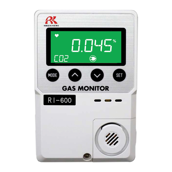
Page 9: Names And Functions For Each Part
3. Product Components 3-2. Names and functions for each part 3-2. Names and functions for each part This section describes the names and functions of the individual parts and LCD display that make up the monitor. Main unit Name Major function Turns the power ON/OFF. - Page 10 3. Product Components 3-2. Names and functions for each part Display Name Major function Operating state display Displays the operating status. Blinks at a normal state. 1st alarm display Lights up or flash in orange at a first alarm state. 2nd alarm display Lights up or flash in red at a second alarm state.
-
Page 11: How To Install
4. How to Install 4-1. Precautions for installation points How to Install 4-1. Precautions for installation points When installing the monitor, never fail to observe the following precautions. Ignoring the precautions may damage the monitor, resulting in inaccurate gas detection. CAUTION ... -
Page 12: Precautions For System Designing
4. How to Install 4-2. Precautions for system designing <Keep the monitor (and its cables) away from noise source devices.> When selecting installation points, avoid a place where high-frequency/high-voltage devices exist. <Do not install the monitor in a place where maintenance of the monitor cannot be performed or where handling the monitor involves dangers.>... - Page 13 - It may be recommended that the surge absorbing part should be attached to the contact for certain load conditions. It must be attached to an appropriate position by checking how the load is activated. RI-600 Alarm contact Power...
-
Page 14: Installation Of Main Unit
4. How to Install 4-3. Installation of main unit 4-3. Installation of main unit Install the main unit on the wall 50 to 180 cm up from the floor. If wall screws are available, remove the screw at the lower part of the main unit to open the cover and install the unit using the mounting holes on the back of the unit. - Page 15 4. How to Install 4-3. Installation of main unit <Maintenance Space> If the installation board (option) is used, secure an installation space above the unit so that it can be installed by sliding. Secure as installation space Installation dimension drawing (Installation board not used) Installation dimension drawing (Installation board used) Compatible with JIS single switch box...
-
Page 16: Precautions For Wiring
4. How to Install 4-4. Precautions for wiring 4-4. Precautions for wiring If the monitor operates on AC or DC power, or inductive load is used at the alarm contact, wiring work is required. The following cables are recommended for wiring the monitor with the power supply, signal cable and contact. - Page 17 4. How to Install 4-4. Precautions for wiring How to connect to terminal plate When cables (wires) are connected to the terminal plate inside the main unit, use the dedicated screwdriver or a compatible flathead screwdriver. When connecting a stranded wire, be sure to press the push button and open the spring while connecting the wire.
- Page 18 4. How to Install 4-4. Precautions for wiring Figure of terminal plate The overview of the terminal plate inside the main unit is as follows: For contact (TN3) For external output signal 1 - 2: ALM1 (First) (4 - 20 mA/0 - 1 V) (TN2) 3 - 4: ALM2 (Second) 1: (+) 2: (-)
-
Page 19: How To Use
5. How to Use 5-1. Before using the monitor How to Use 5-1. Before using the monitor Not only the first-time users but also the users who have already used the monitor must follow the operating precautions. Ignoring the precautions may damage the monitor, resulting in inaccurate gas detection. CAUTION ... -
Page 20: Basic Operating Procedures
5. How to Use 5-3. Basic operating procedures 5-3. Basic operating procedures Normally, the detection mode is activated after the power is turned on. <Detection Mode> The monitor is restarted after recovering from fault. CO2 (long pressing) <Gas Alarm Status> <Maintenance Mode>... -
Page 21: Power-On
5. How to Use 5-4. Power-on 5-4. Power-on - Before turning on the power switch, check that the monitor is installed properly. - Slide the power switch up to power on and down to power off. - Turn on the power switch. - After the monitor completes the start-up, it enters the detection mode. -
Page 22: Modes
5. How to Use 5-5. Modes 5-5. Modes Mode Item LCD display Details Detection concentration Normal state - mode Gas name 1-0 VER Indicate the program version. Version display Fresh air 1-1 AIR Not used. adjustment Show the typical settings. 1-20: First Alarm Setpoint (ALM1) 1-21: Second Alarm Setpoint (ALM2) Maintenance... -
Page 23: User Mode
5. How to Use 5-6. User mode 5-6. User mode WARNING After adjustment is completed, never fail to press the MODE button to return to the detection mode. (If the monitor remains in the user mode, it automatically returns to the detection mode in ten hours.) Detection mode Press the MODE... - Page 24 5. How to Use 5-6. User mode <Setting Display "1-2"> This is used to check the setting of typical menus. 1-2. CONF Press the SET button. First Alarm Setpoint Display Press the SET button to display the first alarm setpoint. Second Alarm Setpoint Display Alarm Delay Time...
-
Page 25: Power-Off
5. How to Use 5-7. Power-off Zero Follower ON/OFF Display Not used. Air Pressure Correction ON/OFF Display Not used. Alarm Summary 5-7. Power-off Slide the power switch down to power off. After turning off the power switch of the monitor, turn off the power supply (100 VAC or 24 VDC) of the monitor. -
Page 26: Alarm Activation And Functions
6. Alarm Activation and Functions 6-1. Gas alarm activation Alarm Activation and Functions 6-1. Gas alarm activation A gas alarm is activated when detected gas concentration reaches the preset alarm setpoint. NOTE The alarm setpoint (first alarm and second alarm) is factory-set. The setting values can be changed in the maintenance mode (P.29). -
Page 27: Fault Alarm Activation
After the monitor is successfully returned from the fault, it restarts with the process normally performed right after it is turned on (initial clear). If the monitor has problems and is repeatedly malfunctioning, contact RIKEN KEIKI immediately. NOTE For information on malfunctions (error messages), see "Troubleshooting" (P.45). -
Page 28: Maintenance
- function. Span Perform span adjustment using a calibration gas. - Adjustment Gas alarm Check the gas alarm using a calibration gas. - check WARNING If an abnormality is found in the monitor, contact RIKEN KEIKI immediately. -
Page 29: Maintenance (Regular Maintenance) Mode
Our qualified service engineers have expertise, knowledge, etc. on the dedicated tools used for services, along with other products. To maintain the safety operation of the monitor, please use our maintenance service. Typical maintenance services are listed as follows. For details, please contact RIKEN KEIKI. <Typical Maintenance Services> Item Services Checks the power supply voltage. - Page 30 7. Maintenance 7-2. Maintenance (regular maintenance) mode Mode Item LCD display Details 2-0 GAS TEST 2-00: Gas Test Maintenance Gas introduction 2-01: Alarm Test mode display 2-02: Fault Alarm Test (Regular 2-03: Display test maintenance) 2-04: Not used (----) 2-1 ZERO Perform the zero adjustment.
- Page 31 7. Maintenance 7-2. Maintenance (regular maintenance) mode <Regular Maintenance Mode> User mode Press the SET button in "1-3. M MOD". Then press the SET button again for three (long pressing) seconds. 2-0. GAS TEST Perform a test with the gas. Similar to the detection condition,the reading changes and an alarm...
- Page 32 7. Maintenance 7-2. Maintenance (regular maintenance) mode 2-3. SDEF Not used. 2-4. SET Specify various settings. 2-5. DISP Provide various detail displays. 2-6. F MODE Not used. 2-7. U MODE Return to the user mode.
- Page 33 7. Maintenance 7-2. Maintenance (regular maintenance) mode <Gas Introduction Display> 2-0. GAS TEST Perform a test with the gas. Similar to the detection mode, the reading changes and an alarm is displayed after the gas is introduced, but the contact is not activated.
- Page 34 7. Maintenance 7-2. Maintenance (regular maintenance) mode 2-03. LCD Perform the LCD display test. 2-04. Not used. To 2-00...
- Page 35 7. Maintenance 7-2. Maintenance (regular maintenance) mode <Zero Adjustment> 2-1. ZERO Perform the zero adjustment. The current concentration is displayed. Supply zero adjustment gas to the sensor. Press the SET button. "PASS" is displayed when adjustment is completed, and "FAIL" is displayed when it fails.
- Page 36 7. Maintenance 7-2. Maintenance (regular maintenance) mode <Span Adjustment> 2-2. SPAN Perform the span adjustment. The current concentration is displayed. Use the ˄ or ˅ button to adjust the reading to the span adjustment gas concentration and press the SET button. "PASS"...
- Page 37 7. Maintenance 7-2. Maintenance (regular maintenance) mode <Environmental Setting> 2-4. SET Specify various settings. 2-40. Not used. 2-41. Not used. 2-42. AL-P Set the alarm setpoint (first, second). Use the ˄ or ˅ button to set the alarm setpoint and press the SET button to confirm...
- Page 38 7. Maintenance 7-2. Maintenance (regular maintenance) mode 2-43. AL-D Set the alarm delay time (seconds). Use the ˄ or ˅ button to set the time (seconds) and press the SET button to confirm it. 2-44. AL-T Not used. 2-45. SP-T Not used.
- Page 39 7. Maintenance 7-2. Maintenance (regular maintenance) mode 2-47. Not used. 2-48. MA20 Adjust the external output (4 mA, 20 mA). Connect an ammeter. Then, use the ˄ or ˅ button to select the value and press the SET button to confirm 2-48.
- Page 40 7. Maintenance 7-2. Maintenance (regular maintenance) mode 2-4A. DATE Set the date/time. Use the ˄ or ˅ button to select each value in the order of year, month, day, hour and minute and press the SET button to confirm...
- Page 41 7. Maintenance 7-2. Maintenance (regular maintenance) mode 2-4b. P-A Not used. 2-4C. ACAL Not used. 2-4d. BZZR Set the buzzer to ON/OFF.
- Page 42 7. Maintenance 7-2. Maintenance (regular maintenance) mode 2-4E. AL-R Set the gas alarm state contact to ON/OFF. 2-4F. MA-O Set the external output signal to ON/OFF.
- Page 43 7. Maintenance 7-2. Maintenance (regular maintenance) mode 2-4H. LCD Set the LCD backlight to ON/OFF. No backlight by standard setting...
-
Page 44: Storage And Disposal
When the monitor is used again after a long-period storage, perform a calibration. CAUTION Contact RIKEN KEIKI for information on readjustment including calibration. 8-3. Disposal of products When the monitor is disposed of, it must be treated properly as an industrial waste in accordance with the local regulations, etc. -
Page 45: Troubleshooting
If the monitor shows a symptom which is not explained in this manual, or still has malfunctions even though remedial actions are taken, please contact RIKEN KEIKI. Symptom/Display Causes... - Page 46 9. Troubleshooting 9. Troubleshooting Symptom/Display Causes Actions Turn off and restart the monitor. Disturbance by noise If a symptom like this is observed frequently, take appropriate measures to eliminate the noise. Improper calibration gas Use the proper calibration gas. concentration Span adjustment impossible Deteriorated sensor...
-
Page 47: Product Specifications
10. Product Specifications 10-1. List of specifications Product Specifications 10-1. List of specifications Non-Dispersive Infrared Ray Detection principle Gas to be detected Carbon dioxide Concentration display LCD digital display (Five-digit, seven-segment/green, orange and red backlight) No backlight by standard setting Detection range 0 - 2000ppm / 0 - 5000ppm / 0 - 10000ppm 0 - 2vol% / 0 - 5vol%... -
Page 48: Appendix
Appendix 11-1. Detection principle of Non-Dispersive Infrared Ray Model RI-600 applies Non-Dispersive Infrared Ray Absorption(NDIR) technique to detect target gas. The infrared beam emitted from the light source passes through the gas cell and reaches to IR sensor. The target gas enters into gas cell from gas inlet. - Page 49 Manual Log Rev. Amendment Issue data First issue 2017/7/7...
Need help?
Do you have a question about the RI-600 and is the answer not in the manual?
Questions and answers