Table of Contents
Advertisement
Quick Links
Advertisement
Table of Contents

Subscribe to Our Youtube Channel
Related Manuals for Riken Keiki PT0E-09810


Summary of Contents for Riken Keiki PT0E-09810
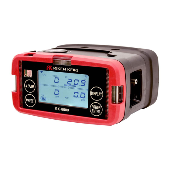
- Page 1 PT0E-09810 Portable Gas Monitor GX-8000 Operating Manual (PT0-098)
-
Page 2: Table Of Contents
<Contents> Outline of the Product ....................3 1-1. Preface ........................3 1-2. Purpose of use ......................3 1-3. Definition of DANGER, WARNING, CAUTION, and NOTE ........3 1-4. Method of confirmation for Standards and Explosion proof specification....3 Important Notices on Safety ..................5 2-1. -
Page 3: Outline Of The Product
(See the list of gases to be detected at the end of this operating manual.) In addition to this operating manual, an operating manual for the data logger management program (option) is available for the gas monitor. Contact RIKEN KEIKI if it is needed. 1-3. Definition of DANGER, WARNING, CAUTION, and... - Page 6 DANGER The specifications of main units are as follows: Pump circuit: Allowable voltage of 4.95 V, allowable current of 1.12 A, and allowable power of 1138 mW Combustible gas sensor circuit: Allowable voltage of 4.95 V, allowable current of 0.834 A, and allowable power of 853 mW Buzzer circuit: Allowable voltage of 4.95 V, allowable current of 0.431 A, and...
- Page 7 DANGER About combination Make sure that the product model on the nameplate and combination of main unit and battery unit is correct. Inappropriate combinations of models deviate from the range of explosion-proof certification. IP protection class: IP20 About use ...
-
Page 8: Warning Cases
2-2. Warning cases WARNING Sampling point pressure The gas monitor is designed to draw gases around it under the atmospheric pressure. If excessive pressure is applied to the gas inlet and outlet (GAS IN, GAS OUT) of the gas monitor, detected gases may be leaked from its inside, thus leading to dangers. -
Page 9: Precautions
2-3. Precautions CAUTION Do not use the gas monitor where it is exposed to oil, chemicals, etc. Do not submerge the gas monitor under water on purpose. Do not use in a place where the gas monitor is exposed to liquids such as oil and chemicals. ... - Page 10 CAUTION Others Pressing buttons unnecessarily may change the settings, preventing alarms from activating correctly. Operate the gas monitor using only the procedures described in this operating manual. Do not drop or give shock to the gas monitor. The water-proof and explosion-proof properties and accuracy may be deteriorated.
-
Page 11: Safety Information
2-4. Safety information The Portable Gas Monitor Model GX-8000 is a gas monitor designed to provide continuous exposure monitoring of combustible gas, oxygen (O ), toxic gas such as carbon monoxide (CO) and hydrogen sulfide S) in hazardous environments. The gas sample is sucked in by build-in micro pump. The battery can be selected either Li-ion battery or alkaline dry battery. - Page 13 DANGER The specifications of main units are as follows: Pump circuit: Allowable voltage of 4.95 V, allowable current of 1.12 A, and allowable power of 1138 mW Combustible gas sensor circuit: Allowable voltage of 4.95 V, allowable current of 0.834 A, and allowable power of 853 mW Buzzer circuit: Allowable voltage of 4.95 V, allowable current of 0.431 A, and...
-
Page 15: Names And Functions For Each Part
3-2. Names and functions for each part <Outline Drawing>... - Page 16 LCD display Displays gas concentrations, alarms, etc. Buzzer sound opening Emits a buzzer sound at an alarm. (Do not block it.) Alarm LED arrays The lamp blinks in response to an alarm. Infrared communication port Used to carry out data communications with a PC in data logger mode.
-
Page 18: How To Use
How to Use 4-1. Before using the gas monitor Not only the first-time users but also the users who have already used the product must follow the operating precautions. Ignoring the precautions may damage the gas monitor, resulting in inaccurate gas detection. 4-2. - Page 19 (1) Open the recharging jack cover of the gas monitor. CAUTION Do not pull the recharging jack cover too hard. It may get damaged. (2) Put the plug of the AC powered charger into the recharging jack of the gas monitor. (3) Connect the AC powered charger to the wall electric outlet.
- Page 20 <Attaching Batteries> (when the optional unit BUD-8000(G) ,BUD-8000(G1) are used) When the gas monitor is used for the first time, or when the battery level is low, attach new AA alkaline batteries. CAUTION <Replacement> Turn off the power of the gas monitor before replacing the batteries. ...
-
Page 24: How To Start The Gas Monitor
4-4. How to start the gas monitor <<Start-up Procedure>>(About 30 seconds) Keep the POWER switch pressed for three seconds or more. ↓ Alarm lamp lights up. All LCDs light up. Buzzer sounds once. (Beep) ↓ Date/Time Display ↓ Battery Voltage Display ↓... - Page 25 ---, and start gas detection. However, notify the abnormality to RIKEN KEIKI promptly. Gas for which there was an abnormality in the sensor cannot be detected. However, the alarm cannot be reset if there is an abnormality in all the sensors.
-
Page 26: How To Detect
4-5. How to detect In the detection mode, put the gas sampling probe close to the detection area and take the reading on the display. Display example <- Display example concentration: 0 %LEL concentration: 20.9 % CO concentration: 0 ppm S concentration: 0 ppm Time: 9:30... - Page 27 CAUTION Before performing gas detection, attach the gas sampling probe provided with the gas monitor to prevent disturbances by air dust. When you measure concentrations of oxygen in inert gases for a long time, the carbon dioxide concentration in the air must be 15 % or less. When you use the gas monitor in the air with a carbon dioxide concentration of 15 % or higher, perform measurement in as short time as possible.
- Page 28 <Manual Memory> Any instantaneous value during measurement can be recorded. Up to 256 points of data can be recorded. When the number of recorded data points reaches the maximum, recorded data will be overwritten, starting from the oldest data. (1) In the detection mode, keep the ▼/RESET switch pressed and press the ▲/AIR switch to prepare for recording (about one second).
-
Page 30: Modes
4-6. Modes Details on each mode are provided as follows. (* Operations are slightly different depending on the type.) Mode Item LCD display Details Detection ― Concentration display Normal state Mode Air Calibration ― [AIR CAL] Perform the zero adjustment. Mode Display and Combustible... -
Page 31: Air Calibration Mode
4-7. Air calibration mode Press the AIR switch. Keep pressing the AIR switch. Changes the display to [Adj HOLD AIR]. When [RELEASE] is displayed, release the AIR switch. A 30-second countdown is started on the LCD. (TYPES-A and E only) When the zero adjustment is successfully completed, [END] is displayed, and you return to... - Page 32 NOTE Air calibration can be performed even when there is a gas alarm. If the air calibration fails, it displays [FAIL AIR CAL] and which sensor has become faulty. Press the RESET swtich to reset the fault alarm (calibration failure).
-
Page 33: Display/Setting Mode
4-8. Display/setting mode This mode allows you to change various displays and settings. Every time the DISPLAY switch is pressed, various screens are displayed in turn. (* Operations are slightly different depending on the type.) Detection Mode Display and Setting Mode Combustible Gas Measurement Combustible Gas Measurement Range Setting... - Page 34 Pump ON/OFF Setting Pump ON/OFF Setting P35 ENTER Used to turn on/off the pump operations. ID Display/Selection ID Display/Selection P36 ENTER Display an ID if it has been registered in advance. Also used to select an ID. Log Data Display Log Data Display ...
- Page 35 <Combustible Gas Measurement Range Setting [HC RANGE]> (TYPE-A and E Only) The models that can display combustible gas levels in two ways, "%LEL range" and "vol% range," automatically switch between these two displays according to the gas concentration or oxygen concentration, from "%LEL range"...
- Page 37 <Full Scale Display/Alarm Setpoint Display/Alarm Test [ALARM-P]> Display the full scale or alarm setpoint values and check the alarm operations for the settings displayed. (1) Press the DISPLAY switch and select the "full scale display/alarm setpoint display/alarm test" from the display/setting mode menu.
- Page 38 <Pump ON/OFF Setting [PUMP OFF]> Used to turn on/off the pump operations. CAUTION While the pump operation is set to OFF, no gas detection is performed because no gas is drawn. The gas monitor does not automatically return to the detection mode if the pump operation is set to OFF.
- Page 39 The data logger management program (option) is required to register or change an ID. Please contact RIKEN KEIKI. (3) Press either the ▲ or ▼ switch to select an ID. Every time the ▲ or ▼ switch is pressed, the ID number increases or decreases (000 - 255).
-
Page 40: How To Exit
<Log Data Display [REC.DATA]> Display concentration data recorded to the manual memory. (1) Press the DISPLAY switch and select the log data display from the display/setting mode menu. The following screens are displayed in turn on the gas monitor. (2) Press the ENTER switch to display the log data. NOTE If you do not want to display the log data, press the DISPLAY switch to return to the display/setting mode menu. -
Page 41: Operations And Functions
Operations and Functions 5-1. Gas alarm activation Gas alarm: Triggered when the concentration of detected gas reaches or exceeds the alarm setpoint value. <<Self-latching>> Alarm display: Notified by blinking of a gas concentration value display, sounding of the buzzer, and lighting of the lamp. - Page 42 <Display Operation> Gas Concentration Display In a gas alarm, the gas concentration display and the alarm type display blink. In case of over the detection range (Over Scale), [∩∩∩] is displayed on the LCD. Display example Alarm Lamp The alarm consists of two steps. Each of them is triggered when the respective alarm setpoint value is reached to or exceeded.
-
Page 43: Fault Alarm Activation
5-3. Other functions <Calibration History/Various Trend/Event History Functions> The gas monitor has history and trend functions. To use these functions, contact RIKEN KEIKI. NOTE The data logger management program (option) is required to use the history and trend functions. Please... -
Page 44: Maintenance
Maintenance This is an important instrument for the purpose of safety. To maintain the performance of the gas monitor and improve the reliability of safety, perform a regular maintenance. 6-1. Maintenance intervals and items Daily maintenance: Perform maintenance before beginning to work. ... -
Page 45: Gas Calibration Method
Consumable Parts 6-2. Gas calibration method The span adjustment requires dedicated equipment and a calibration gas. Request RIKEN KEIKI for it. If you perform the span adjustment for yourself, prepare these tools in advance and perform the adjustment in accordance with the 'Maintenance Manual.' CAUTION Do not use a lighter gas to check the sensitivity of the gas monitor. - Page 47 How to replace the activated carbon filter CAUTION Turn off the power of the gas monitor before replacing the activated carbon filter. Do not remove the activated carbon filter knob unless the activated carbon filter is to be replaced.
- Page 48 The operation of most of the periodical replacement parts must be checked after replacement by a qualified service engineer. For the stable operation of the gas monitor and safety, ask a qualified service engineer to take care of replacement of the parts whose operation must be checked. Please contact RIKEN KEIKI.
-
Page 49: Storage And Disposal
Therefore, it is necessary to store the gas monitor with the batteries in it. 7-2. Procedures to use the gas monitor again CAUTION When you use a stopped/stored gas monitor again, do not forget to perform a gas calibration. For information on readjustment including gas calibration, please contact RIKEN KEIKI. -
Page 50: Disposal Of Products
When disposing of the gas detector in EU member states, sort the batteries as specified. Handle the removed batteries according to the classified refuse collection system and recycling system based on the regulations of EU member states. Contact RIKEN KEIKI for disposal. Removing batteries See '4-2. Preparation for start-up' and take out the batteries. -
Page 51: Troubleshooting
Abnormalities of internal Error No.031 FLASH Sensor A sensor has failed. Request RIKEN KEIKI to replace the sensor. abnormalities (Only at power-on, press the RESET switch to continue [FAIL SENSOR] the operation using only the normal sensors to detect other gases.) A low battery The battery level is low. - Page 52 [FAIL LOW FLOW] The gas sampling hose Check the gas sampling hose for connections, clogging, is clogged. twisting, etc. The pump has Request RIKEN KEIKI to replace the pump. deteriorated. Fresh air Fresh air is not supplied Supply fresh air. adjustment cannot around the gas monitor.
-
Page 53: Product Specifications
Product Specifications 9-1. List of specifications <TIIS specifications> Model GX-8000 Detection principle Galvanic cell (OS) New ceramic catalytic(NC)/ Electrochemical (ES) Electrochemical (ES) Thermal conductivity(TE) Detectable gas Oxygen Combustible gas Hydrogen sulfide Carbon monoxide (HC/CH ) *1 (CO) Measuring range 0 - 25 vol% 0 - 100 %LEL 0 - 30 ppm 0 - 150 ppm... - Page 54 <ATEX/IECEx specifications> Model GX-8000 Detection principle Galvanic cell (OS) New ceramic catalytic(NC)/ Electrochemical (ES) Electrochemical (ES) Thermal conductivity(TE) Detectable gas Oxygen Combustible gas Hydrogen sulfide Carbon monoxide (HC/CH (CO) Measuring range 0 - 25 vol% 0 - 100 %LEL 0 - 30 ppm 0 - 150 ppm <Service range>...
-
Page 55: List Of Accessories
9-2. List of accessories Li-ion battery unit (BUL-8000 (G), BUL-8000 (G1)) AC powered charger Standard Shoulder strap accessories Gas sampling hose (1 m spiral) Gas sampling probe Dry battery unit (BUD-8000 (G), BUD-8000 (G1)) ... -
Page 56: Definition Of Terms
Definition of Terms vol% Gas concentration indicated in the unit of one-hundredth of the volume Gas concentration indicated in the unit of one-millionth of the volume %LEL An abbreviation for "Lower Explosion Limit." LEL refers to the lowest concentration of a combustible gas in air capable of causing explosion when ignited.
Need help?
Do you have a question about the PT0E-09810 and is the answer not in the manual?
Questions and answers