Table of Contents
Advertisement
Request for the Customers
Read and understand this operating manual before using this gas monitor.
Use it in accordance with this operating manual.
Regardless of warranty period, we shall not make any indemnification for accidents and
damage caused by using this gas monitor.
Make sure to read the warranty policy specified on the warranty.
Because this is a safety unit, a regular maintenance for every six months and daily
maintenance must be performed.
If any abnormality is found in the gas monitor, notify it to RIKEN KEIKI immediately.
(Visit our Web site to find your nearest RIKEN KEIKI office.)
Portable Gas Monitor
GX-8000
(Type LEL)
Operating Manual
(PT0-098)
PT0E-1091
Advertisement
Table of Contents

Related Manuals for Riken Keiki GX-8000


Summary of Contents for Riken Keiki GX-8000
-
Page 1: Operating Manual
Because this is a safety unit, a regular maintenance for every six months and daily maintenance must be performed. If any abnormality is found in the gas monitor, notify it to RIKEN KEIKI immediately. (Visit our Web site to find your nearest RIKEN KEIKI office.) -
Page 2: Table Of Contents
Procedures to use the gas monitor again ..............38 7-3. Disposal of products ....................39 Troubleshooting ....................... 40 Product Specifications ..................... 42 9-1. List of specifications ....................42 9-2. List of accessories ....................44 Definition of Terms ....................45 GX-8000 - 1 -... -
Page 3: Outline Of The Product
Outline of the Product 1-1. Preface Thank you for choosing our portable gas monitor GX-8000 (Type LEL). Please check that the model number of the product you purchased is included in the specifications on this manual. This manual explains how to use the gas monitor and its specifications. It contains information required for using the gas monitor properly. -
Page 4: Important Notices On Safety
Oxygen-deficient air or other gases may blow out from the gas exhausting outlet. Never inhale the air or gases. High-concentration (more than LEL) gases may blow out. Never use fire near the gas monitor. GX-8000 - 3 -... -
Page 5: Warning Cases
Do not wash the gas monitor in a washing machine or ultrasonic cleaner. Do not block the buzzer sound opening. No alarm sound can be heard. Do not remove the battery unit while the power is ON. GX-8000 - 4 -... -
Page 6: Precautions
Since this is a safety unit, a regular maintenance must be performed to ensure safety. Continuing to use the gas monitor without performing a maintenance will compromise the sensitivity of the sensor, thus resulting in inaccurate gas detection. GX-8000 - 5 -... - Page 7 In case the gas monitor is used for detection in the presence of silicone, etc., be sure to check the gas sensitivities before using it again. GX-8000 - 6 -...
-
Page 8: Safety Information
Observe the followings to maintain an explosion-proof system. <Overseas Specifications> The Portable Gas Monitor Model GX-8000 is a gas monitor designed to provide continuous exposure monitoring of combustible gas, oxygen (O2), toxic gas such as carbon monoxide (CO) and hydrogen sulfide (H2S) in hazardous environments. -
Page 9: Product Components
3-1. Main unit and standard accessories Product Components 3-1. Main unit and standard accessories After opening the package, check the main unit and accessories. If anything in the following list is not included, contact RIKEN KEIKI. <Main Unit> <Standard Accessories> AA alkaline battery: 3... -
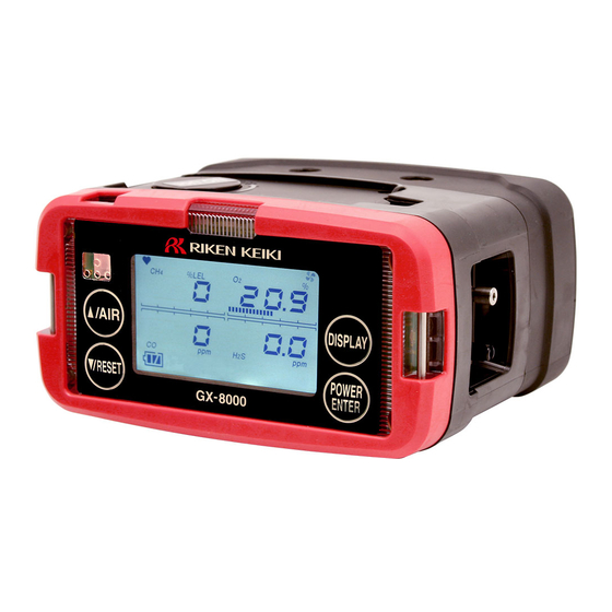
Page 10: Names And Functions For Each Part
Additionally, a nameplate indicating a compatible model is affixed on the top of the battery unit. Check this information and use a correct combination. Printing for identification 3-2. Names and functions for each part <Outline Drawing> GX-8000 - 9 -... - Page 11 Do not remove the panel sheet on the display. The water-proof and dust-proof performances will be deteriorated. Do not affix a label on the infrared port. Infrared communications can no longer be conducted. GX-8000 - 10 -...
-
Page 12: Lcd Display
The meanings of battery level icons are as follows: : Sufficient / : Low / : Needs charging If the battery level is lower than the above, the inside of the battery icon starts to blink ( GX-8000 - 11 -... -
Page 13: How To Use
Check that there is no bend or hole in the gas sampling hose. Check that the filter in the gas sampling probe is free of dust or clogging. Check that the gas monitor, gas sampling probe, and gas sampling hose are connected properly. GX-8000 - 12 -... - Page 14 (2) Paying attention to the polarities of batteries, replace all the three batteries with new ones. (3) Close the battery cover and tighten the battery cover fixing screw. GX-8000 - 13 -...
- Page 15 The temperature of the gas monitor is high immediately after charging is completed. Let it leave for 10 minutes or more before using it. Otherwise, correct measurements may not be obtained. When fully charged batteries are charged again, the charging indicator lamp does not go on. GX-8000 - 14 -...
- Page 16 Do not damage the rubber seal. To maintain the water-proof and dust-proof performances, it is recommended to replace the rubber seal every two years, whether or not it has an abnormality. GX-8000 - 15 -...
- Page 17 Insert the sampling hose to the gas inlet (GAS IN) until it clicks into place to ensure connection. CAUTION Use only a gas sampling hose specified by RIKEN KEIKI. Use the gas monitor with the gas sampling probe connected so that no foreign substance is drawn into it.
-
Page 18: Basic Operating Procedures
Normally, the detection mode is used for normal operations. (The detection mode is activated after the power is turned on.) <<Detection Mode>> RESET AIR (long pressing) <<Gas Alarm Status>> (Self-latching <Reset after <<Air Calibration Mode>> Recovery to Normal Status>) DISPLAY <<Fault Alarm Status>> (Self-latching) <<Display and Setting Mode>> GX-8000 - 17 -... -
Page 19: How To Start The Gas Monitor
Alarm lamp lights up. All LCDs Light Up. Buzzer sounds once. (Beep) ↓ Date/Time Display ↓ Battery Voltage Display ↓ Gas Name Display ↓ Full Scale Display ↓ First Alarm Setpoint Display ↓ Second Alarm Setpoint Display GX-8000 - 18 -... - Page 20 NOTE A sensor abnormality alarm is issued before the detection mode is entered if there is any abnormality in the sensor. Promptly contact RIKEN KEIKI. Gases cannot be detected if there is any abnormality in the sensor. If there is an abnormality in the built-in clock, a fault alarm FAIL CLOCK may be issued. Press the RESET button.
-
Page 21: How To Detect
If a low battery alarm occurs, gas detection cannot be conducted. If the alarm occurs during use, turn off the power and promptly charge the batteries in a non-hazardous area. Do not block the buzzer sound opening. No alarm sound can be heard. GX-8000 - 20 -... - Page 22 Performing fresh air adjustment before cleaning it completely will result in inaccurate adjustment, giving adverse influence on measurement. In such a case, remove the gas sampling hose before performing fresh air adjustment to avoid inaccurate adjustment. GX-8000 - 21 -...
- Page 23 (2) Press the ENTER switch. The date and the instantaneous value at the time when the ENTER switch is pressed are recorded. (3) When END is displayed, the recording is completed. Returns to the detection mode. GX-8000 - 22 -...
-
Page 24: Modes
Used to turn on/off the pump operations. ON/OFF Setting ID Setting ID SELECT Display an ID if it has been set in advance. Also used to change or set an ID. Log Data REC.DATA Display data recorded to the manual Display memory. GX-8000 - 23 -... -
Page 25: Air Calibration Mode
If there is a sudden temperature change of 15ºC or more between the storage and operation locations, turn on the power of the gas monitor, let it leave for about 10 minutes in a similar environment to the operation location, and perform air calibration in fresh air before using it. GX-8000 - 24 -... - Page 26 If the air calibration fails, it displays "FAIL" - "AIR CAL" and which sensor has become faulty. Press the RESET button to reset the fault alarm (calibration failure). When the alarm is reset, the value before calibration is displayed. If CH4 sensor is faulty GX-8000 - 25 -...
-
Page 27: Display/Setting Mode
Display an ID if it has been registered in advance. Also used to select an ID. Log Data Display Log Data Display ENTER P32 Display concentration data recorded to the manual memory. To Detection Mode GX-8000 - 26 -... - Page 28 (5) Press the DISPLAY switch to exit the alarm setpoint display or alarm test. The display/setting mode menu is displayed again. (6) After completion, press the DISPLAY switch several times until it returns to the detection mode. GX-8000 - 27 -...
- Page 29 While the pump operation is set to OFF, only the ENTER switch is enabled. (4) To return to the detection mode, press the ENTER switch to set the pump operation to ON. (5) After completion, press the DISPLAY switch several times until it returns to the detection mode. GX-8000 - 28 -...
- Page 30 The data logger management program (option) is required to register or change an ID. Please contact RIKEN KEIKI. (3) Press either the ▲ or ▼ switch to select an ID. Every time the ▲ or ▼ switch is pressed, the ID number increases or decreases (000-255).
-
Page 31: How To Exit
NOTE If the display is not zero when the power is turned off, a purge operation may be performed for 30 seconds at the maximum to clean the inside of the gas monitor. GX-8000 - 30 -... -
Page 32: Operations And Functions
Repeatedly blinks at about Repeatedly blinks at about one second intervals. 0.5 second intervals. 0.5 second intervals. LCD display Gas concentration and Gas concentration and Gas concentration and WARNING display blink. ALARM display blink. OVER display blink. GX-8000 - 31 -... - Page 33 1 second interval RESET 0.5 second interval Second alarm setpoint First alarm setpoint Time Alarm lamp, Buzzer WARNING Issuance of a gas alarm indicates that there are extreme dangers. Take proper actions based on your judgment. GX-8000 - 32 -...
-
Page 34: Fault Alarm Activation
5-3. Other functions <Calibration History/Various Trend/Event History Functions> The gas monitor has history and trend functions. To use these functions, contact RIKEN KEIKI. NOTE The data logger management program (option) is required to use the history and trend functions. Please contact RIKEN KEIKI. -
Page 35: Maintenance
Check the alarm lamp and buzzer for normal operation using the alarm test function. Span Perform the span adjustment by using the Adjustment calibration gas. Gas Alarm Check the gas alarm by using the Check calibration gas. GX-8000 - 34 -... -
Page 36: Gas Calibration Method
Perform span adjustment of sensors using a calibration gas at least once every six months. The span adjustment requires dedicated equipment and a calibration gas. Request RIKEN KEIKI for it. If you perform the span adjustment for yourself, prepare these tools in advance and perform the adjustment in accordance with the "Maintenance Manual."... -
Page 37: How To Clean
The sensor life has expired if, for example, the sensors cannot be calibrated in span adjustment, the readings do not come back after fresh air adjustment, or the readings fluctuate. Contact RIKEN KEIKI. The warranty period is one year for all the sensors. - Page 38 The operation of most of the periodical replacement parts must be checked after replacement by a qualified service engineer. For the stable operation of the gas monitor and safety, ask a qualified service engineer to take care of replacement of the parts whose operation must be checked. Please contact RIKEN KEIKI. GX-8000 - 37 -...
-
Page 39: Storage And Disposal
7-2. Procedures to use the gas monitor again CAUTION When you use a stopped/stored gas monitor again, do not forget to perform a gas calibration. For information on readjustment including gas calibration, please contact RIKEN KEIKI. GX-8000 - 38 -... -
Page 40: Disposal Of Products
When the gas monitor is disposed of, it must be treated properly as an industrial waste in accordance with the local regulations. WARNING Dispose of the batteries in accordance with procedure specified by the local authority. GX-8000 - 39 -... -
Page 41: Troubleshooting
FRAM Error No.031 Abnormalities of internal FLASH Sensor A sensor has failed. Request RIKEN KEIKI to replace the sensor. abnormalities FAIL SENSOR A low battery The battery level is low. Li-ion battery unit: Turn off the power and charge it in a voltage alarm is non-hazardous area. - Page 42 FAIL LOW FLOW The gas sampling hose Check the gas sampling hose for connections, clogging, is clogged. twisting, etc. The pump has Request RIKEN KEIKI to replace the pump. deteriorated. Fresh air Fresh air is not supplied Supply fresh air. adjustment cannot around the gas monitor.
-
Page 43: Product Specifications
Approx. 154 (W) x 81 (H) x 127 (D) mm (projection portions excluded) Weight About 1.0 kg (when BUD-8000(G) is used) or about 1.1 kg (when BUL-8000(G) is used) * Specifications subject to changes without notice. GX-8000 - 42 -... - Page 44 Approx. 154 (W) x 81 (H) x 127 (D) mm (projection portions excluded) Weight About 1.0 kg (when BUD-8000(G) is used) or about 1.1 kg (when BUL-8000(G) is used) * Specifications subject to changes without notice. GX-8000 - 43 -...
-
Page 45: List Of Accessories
Gas sampling hose 30 m with plummet accessories Filter tube Filter tube fixing belt Water trap Relay tube Set of gas bags Span cans Demand flow valve Data logger management program GX-8000 - 44 -... -
Page 46: Definition Of Terms
10 Definition of Terms Definition of Terms An abbreviation for "Lower Explosion Limit." LEL refers to the lowest concentration of a combustible gas in air capable of causing explosion when ignited. GX-8000 - 45 -...
Need help?
Do you have a question about the GX-8000 and is the answer not in the manual?
Questions and answers
what is the difference between GX and RX models? DO both meters measure in inerted conditions or only one ? which one is suitable for inerted condition? Are all sensors suitable for inerted?