Advertisement
Quick Links
Advertisement

Subscribe to Our Youtube Channel
Related Manuals for NIPPON POP RIVETS AND FASTENERS PNT800 Series

Summary of Contents for NIPPON POP RIVETS AND FASTENERS PNT800 Series
- Page 1 Read this manual thoroughly before you start and use the PNT800 according to the instructions. Store this manual where the person who uses the tool may refer to it easily. NIPPON POP RIVETS AND FASTENERS LTD. ...
-
Page 2: Table Of Contents
PNT800 CONTENTS Safety Precautions ・ ・ ・ ・ 1 1.Part names ・ ・ ・ ・ 4 2.Outline ・ ・ ・ ・ 5 3.Specifications ・ ・ ・ ・ 6 4.Preparations for use ・ ・ ・ ・ 7 5.Precautions on use ・... -
Page 3: Safety Precautions
PNT800 Safety Precautions -Read all the safety precautions carefully before you use this tool and observe them carefully in practice. -The safety precautions are classified as follows: WARNING! Incorrect operation caused by failure to observe this type of precaution could cause death or serious injury. Caution! Incorrect operation caused by failure to observe this type of precaution could cause injury or physical damage. - Page 4 PNT800 Caution! 1. Before servicing this tool, replacing any of its parts, or otherwise assembling or disassembling it, disconnect all compressed air couplings to make sure it is not supplied with compressed air. If you start to work on this tool while it is supplied with compressed air, parts or oil could fly out or the tool could start moving unexpectedly, causing accident or injury.
- Page 5 PNT800 10. Never use organic solvents on the handle, rear case, front case and trigger (these parts are all made of polycarbonate). Breakage of these parts above could cause parts to fly off, causing accident or injury. 11. Wear protective gloves while using this tool. Your fingers or hands could get trapped or squashed in the mandrel, causing accident or injury.
-
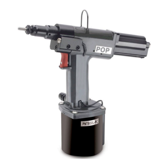
Page 6: 1.Part Names
PNT800 1. Part names Front case Nose housing Rear case Fill screw Nose piece Exhaust holes Mandrel Lock nut Control knob Coupler Trigger ( Plug ) Coupler ( Socket ) Handle Hose Exhaust hole Chamber Not attached Thread size (Rc 1/4) Warning label... - Page 7 PNT800 2. Outline The PNT800 is a small, light tool for fastening Pop Nuts. It is driven by compressed air. Table 2-1 lists the Pop Nuts that can be fastened using this tool. The nosepiece and mandrel must be changed to fit some sizes of Pop Nut. (See table 2-2) Table 2-1 Pop Nuts that can be fastened using this tool Size Pop nut type...
- Page 8 PNT800 3. Specifications Table 3-1 Specifications Model PNT800 Weight 1.68kg Overall length 288mm Overall height 263mm Stroke 1.3~6.5mm Compressed air pressure required 0.5~0.6MPa Pop-Nut that may be fastened See table 2-1 (p.5) Figure 3-1...
-
Page 9: 4.Preparations For Use
PNT800 4. Preparations for use 1. Check that the right nosepiece and mandrel are fitted for the Pop Nut. Adjust the protruding length of the mandrel. (Refer to page 15 for details of replacement and adjustment). 2. The coupling diameter of the compressed air supply coupling is Rc 1/4. Connect a joint or coupler of connection diameter R1/4 to supply compressed air. - Page 10 PNT800 4. Stroke Adjustment Adjust the stroke length according to POP Nut size and the thickness of workpiece. Note: The stroke increases and decreases by change of air pressure (about 0.1mm per 0.1MPa) and makes the air pressure constant as much as possible. 《Procedure》...
- Page 11 PNT800 (3)Proper stroke for POP Nut ・ Confirm stroke ( S , E) corresponding to the POP Nut and the max. min. workpiece thickness used. ・ Adjust the stroke E and adjust proper stroke (S min. max. −S Formula of stroke Thread size Maximum Minimum...
-
Page 12: 5.Precautions On Use
PNT800 5. Precautions on use The following precautions must be observed to ensure that the performance and service life of this tool are maintained. 1. Use the correct compressed air pressure Use compressed air at a pressure in the range 0.5~0.6 MPa. If the compressed air pressure used exceeds the range above, this tool will break down and accident or injury could result. -
Page 13: 6.How To Use The Pnt800
PNT800 6. How to use the PNT800 Before setting Pop Nuts with this tool, refer to the section "4. Preparations for use" on pages seven and eight. 《Procedure》 1. Mounting When the Pop Nut is gripped gently and pressed by the mandrel with a force of approximately 49N or more, the mandrel turns clockwise. - Page 14 PNT800 2. Fastening and detachment Push the Pop Nut perpendicularly into the hole in the base material and pull the trigger (Figure 6-3). Keep pulling the trigger throughout fastening and detachment. Otherwise, detachment cannot be completed. The Pop Nut is fastened and the tool automatically switches to counterclockwise rotation to detach from the Pop Nut (Figure 6-4).
- Page 15 PNT800 3. Stopping the mandrel's counterclockwise rotation. Release the trigger to stop the mandrel (Figure 6-7). Trigger Release Figure 6-9 Figure 6-8 Figure 6-7 Regular mandrel cleaning and lubricant -Clean the mandrel after every 50〜60 fastenings. (See Figures 6-8 and 6-9) After fastening tens of Pop Nuts, metal fragments can stick to the mandrel and it can run short of lubrication, making it impossible to mount Pop Nuts smoothly.
-
Page 16: 7.Maintenance And Testing
PNT800 (2) If the Pop Nut jams and the strength of the air motor is insufficient to detach the mandrel. ① Detach the coupler to stop the supply of compressed air. ② Line up the female screw of the lock pin holder with the hole in the side of the nose housing and screw the cap screw provided (M4×20) into the lock pin holder (Figure 6-11). - Page 17 PNT800 2. Mandrel replacement, nosepiece replacement and mandrel protrusion length adjustment Use the designated parts to match the Pop Nut you will be using. (See p.5 table 2-2) Replace any parts that become worn or damaged. (1) Mandrel replacement 《Procedure》 ①...
- Page 18 PNT800 ③ Screw the lock nut and nosepiece into the nose housing. ④ Open end: Screw a Pop Nut onto the mandrel and adjust the nosepiece so that approximately one thread of the mandrel screw thread extends beyond the Pop Nut (Figure 7-5).
- Page 19 PNT800 (6) Adjust the total length of the assembly to 66±0.1mm, and tighten the lock screw on the control knob hard. (Figure 7-12) (Figure 7-12) (7) Push the assembly into the body of the tool, and reverse the above procedure to reassemble all parts. (8) Loosen the lock screw on the control nut and turn the control knob to the right until the control nut stops at the end of its movement, and then tighten the lock screw.
- Page 20 PNT800 4. Oil replacement If the stroke gets too short due to a lack of hydraulic oil (if a proper caulk stroke is impossible, even after stroke adjustment), follow the procedure below to replace the hydraulic oil. If the stroke again becomes inadequate immediately after replacement of oil, the oil seal must be replaced.
- Page 21 PNT800 Chamber Air piston assembly Tube Truss screw (4pcs.) Handle Figure 7-15 Figure 7-16 (5) Dump the old hydraulic oil from the handle. (6) Pour the new hydraulic oil into the hole in the handle (Figure 7-17). Pour the oil in until its surface is level with the backup ring (Figure 7-18). Back up ring Penta.
- Page 22 PNT800 (8) After replacement of the hydraulic oil, line up the air piston assembly and the tube insertion hole in the handle lower and push the tube into place (Figure 7-20). Pass the tube into the tube insertion holes in the air piston assembly and the handle core (Figure 7-21).
- Page 23 PNT800 8.Troubleshooting (If you cannot fix the tool after checking the content of this section, send it to your supplier or one of our offices for repair.) Problem Cause Action Cannot mount the 1.Parts are not correct. -Change to the correct parts for the POP NUT.
- Page 24 PNT800 Problem Cause Action Mandrel 1.Life of the Mandrel -Replace the Mandrel to new one. damages, (See p.15) breaks. 2.Attempted doulbe setting of POP -Operate correctly. NUT. (See p.11) -Replace the damaged parts to new one. (See p.14) 3.The stroke is excessive. -Adjust the stroke correctly.
-
Page 25: 9.Parts List
PNT800 9.Parts List Product No. Product name Q'ty Product No. Product name Q'ty PNT600-01-□ Mandrel PNT600-41A R-joint adapter PNT600-02-□ Nose piece PNT600-42 O-ring S9-1A PNT600-03 Lock nut PNT600-43 R-joint spacer PNT600-04A Nose housing PNT600-44A R-joint PNT600-05A Spin pull head case PNT600-45A Rear case PNT600-06A Spin pull head PNT600-46 Truss head screw M3×12 PNT600-07A Mast housing PNT600-47 Handle upper PNT600-08A Joint PNT600-48 Front case PNT800-15 Return spring PNT600-49... - Page 26 PNT800 Product No. Product name Q'ty Product No. Product name Q'ty 83 PNT800-09 J-valve cap 109 PNT600-109 Retaining ring RTW8 84 PNT800-10 T-valve rear case 110 PNT600-110 Casing 85 PNT600-85 O-ring S7-1A 111 PNT600-111 Ball bearing 695 86 SPG5035 Spring 112 PNT600-112 Rear plate 87 PNT800-11 T-valve center case 113 PNT600-113 Rotor 88 PNT800-12 T-valve front case 114 PNT600-114 Blade 89 PNT600-89...
-
Page 27: 10.Cross-Sectional Diagram Of The Pnt800
PNT800 10−1.Cross-sectional diagram of the PNT800... - Page 28 PNT800 10−2.Exploded diagram of the compressed air motor...
Need help?
Do you have a question about the PNT800 Series and is the answer not in the manual?
Questions and answers