Table of Contents
Advertisement
Quick Links
Advertisement
Table of Contents

Related Manuals for Siemens SIMATIC ET 200SP TM ECC 2xPWM ST


Summary of Contents for Siemens SIMATIC ET 200SP TM ECC 2xPWM ST
- Page 3 Preface Documentation guide Product overview SIMATIC Wiring ET 200SP Technology module TM ECC Configuring/address space 2xPWM ST (6FE1242-6TM10- 0BB1) Programming Manual Interrupts/diagnostic messages Technical specifications 04/2018 A5E42681298B-AA...
- Page 4 Note the following: WARNING Siemens products may only be used for the applications described in the catalog and in the relevant technical documentation. If products and components from other manufacturers are used, these must be recommended or approved by Siemens. Proper transport, storage, installation, assembly, commissioning, operation and maintenance are required to ensure that the products operate safely and without any problems.
-
Page 5: Preface
Siemens' products and solutions undergo continuous development to make them more secure. Siemens strongly recommends that product updates are applied as soon as they are available and that the latest product versions are used. Use of product versions that are no longer supported, and failure to apply the latest updates may increase customers' exposure to cyber threats. - Page 6 Preface See also IndustrialSecurity (http://www.siemens.com/industrialsecurity) http://support.automation.siemens.com (http://support.automation.siemens.com) Technology module TM ECC 2xPWM ST (6FE1242-6TM10-0BB1) Manual, 04/2018, A5E42681298B-AA...
-
Page 7: Table Of Contents
Table of contents Preface ..............................3 Documentation guide ..........................7 Product overview ..........................11 Properties ..........................11 Wiring ..............................17 Terminal assignment and power supply ................. 17 Connection examples ......................25 Configuring/address space ........................31 Configuring ..........................31 Reaction to CPU STOP ......................32 Required I/O address space .................... -
Page 9: Documentation Guide
S7-1500 and ET 200MP systems, e.g. diagnostics, communication, motion control, Web server, OPC UA. You can download the documentation free of charge from the Internet (http://w3.siemens.com/mcms/industrial-automation-systems-simatic/en/manual- overview/Pages/Default.aspx). Changes and supplements to the manuals are documented in a Product Information. Technology module TM ECC 2xPWM ST (6FE1242-6TM10-0BB1) - Page 10 You must register once to use the full functionality of "mySupport". You can find "mySupport" on the Internet (https://support.industry.siemens.com/My/ww/en). "mySupport" - Documentation In the Documentation area in "mySupport" you can combine entire manuals or only parts of these to your own manual.
- Page 11 ● Manuals, characteristics, operating manuals, certificates ● Product master data You can find "mySupport" - CAx data on the Internet (http://support.industry.siemens.com/my/ww/en/CAxOnline). Application examples The application examples support you with various tools and examples for solving your automation tasks. Solutions are shown in interplay with multiple components in the system - separated from the focus on individual products.
- Page 12 You can find SIEMENS PRONETA on the Internet (https://support.industry.siemens.com/cs/ww/en/view/67460624). SINETPLAN SINETPLAN, the Siemens Network Planner, supports you in planning automation systems and networks based on PROFINET. The tool facilitates professional and predictive dimensioning of your PROFINET installation as early as in the planning stage. In addition, SINETPLAN supports you during network optimization and helps you to exploit network resources optimally and to plan reserves.
-
Page 13: Product Overview
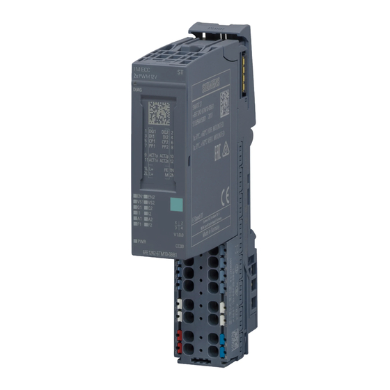
⑤ ⑪ LEDs for channel status BU type ⑥ ⑫ LED for supply voltage Article number Figure 2-1 View of the SIMATIC ET 200SP TM ECC 2xPWM ST module Technology module TM ECC 2xPWM ST (6FE1242-6TM10-0BB1) Manual, 04/2018, A5E42681298B-AA... - Page 14 2.1 Properties Properties The SIMATIC ET 200SP TM ECC 2xPWM ST technology module is used for control and monitoring of conductive charging of electric vehicles on the three-phase AC grid according to the standard IEC 61851-1, charging mode Mode 3. It provides two charging outlets for this purpose.
- Page 15 ● TIA Portal as of version V14 SP1 Distributed operation in a system from a different manufacturer: ● PROFINET GSD files (https://support.industry.siemens.com/cs/document/57138621?dti=0&lc=en-US) Accessories The following accessories can be used with the module and is not included in the scope of delivery: ●...
- Page 16 Product overview 2.1 Properties You will find additional information on installation in the ET 200SP distributed I/O system System Manual (https://support.industry.siemens.com/cs/document/58649293?dti=0&lc=en- US). Disposal Electric and electronic devices do not belong in household waste. Dispose of the product according to the valid legal regulations at the end of its service life. By doing so you will meet the legal obligations and help protect the environment.
- Page 17 Product overview 2.1 Properties Firmware update Note Firmware update Note that a firmware update can only be performed in STOP mode. When you trigger the update in the TIA Portal, you must switch the CPU to STOP manually. No dialog prompting you to do so appears in this case.
-
Page 19: Wiring
Product information for documentation of the ET 200SP Distributed I/O System (http://support.automation.siemens.com/WW/view/en/73021864). Information regarding selection of a suitable BaseUnit can be found in the ET 200SP Distributed I/O System System Manual (http://support.automation.siemens.com/WW/view/en/58649293) and in the ET 200SP BaseUnits Manual (http://support.automation.siemens.com/WW/view/en/58532597/133300). Technology module TM ECC 2xPWM ST (6FE1242-6TM10-0BB1) Manual, 04/2018, A5E42681298B-AA... - Page 20 Wiring 3.1 Terminal assignment and power supply Pin assignment of the BaseUnit BU type B1 The table shows the pin assignment of the BaseUnit BU20-P12+A0+4B (6ES7193-6BP20- 0BB1). The power supply of this BaseUnit is not looped through, which means downstream BaseUnits are not supplied by this BaseUnit.
- Page 21 Wiring 3.1 Terminal assignment and power supply Pin assignment of the BaseUnit BU type B0 To connect to or use an existing potential group, you must use the following BaseUnit. A new potential group is not created with the BaseUnit BU type B0 (BU20-P12+A4+0B / 6ES7193-6BP20-0BB0).
- Page 22 You can configure the read-back input via the TIA Portal. Control Pilot CP0 and CP1 The SIMATIC ET 200SP TM ECC 2xPWM ST technology module can operate two conductive charging outlets in accordance with the standard IEC61851-1. The device forms a Control Pilot signal for every charging outlet.
- Page 23 Wiring 3.1 Terminal assignment and power supply Table 3- 1 Control Pilot (PWM) Control Pilot (PWM) Meaning / available charging current < 8% Charging not permitted ≥ 8% .. < 10% ≥ 10% .. < 85% available current = PWM [%] × 0.6 A/% Example: PWM = 50% →...
- Page 24 Wiring 3.1 Terminal assignment and power supply Table 3- 2 States and level U State Vehicle connected S2 Charging is possi- Comment a a) open 12 V = 0 V open R2 determined closed Vehicle ready R3 = 1.3 kΩ ± 3% Ventilation not required R3 = 270 Ω...
- Page 25 Wiring 3.1 Terminal assignment and power supply Pull up 330 Ω Figure 3-2 Plug Present circuit The technology module assigns a current carrying capacity to the resistance value measured at the PP terminal (R ) according to the following table. Table 3- 4 Permitted current in the charging cable or charging connector Resistance R...
- Page 26 Note L+- and M isolation on the SIMATIC ET 200SP TM ECC 2xPWM ST technology module provided by the BaseUnit type B1. The L+ and M connectors on the BaseUnit of type B1 are galvanically isolated from the neighboring BaseUnits to the left and right.
-
Page 27: Connection Examples
Wiring 3.2 Connection examples Connection examples Block diagrams The circuit diagrams below show the schematic wiring of the technology module with the typical options for use of the feedback input. Figure 3-3 Connecting the technology module with feedback from contactor status (when using a BU type B1) Technology module TM ECC 2xPWM ST (6FE1242-6TM10-0BB1) Manual, 04/2018, A5E42681298B-AA... - Page 28 Wiring 3.2 Connection examples Figure 3-4 Detail view contactor circuit Figure 3-5 Detail view of protective wiring with optional DQ in the supply line Note We recommend supplying the output contactor via an additional standard DQ To ensure the best possible protection during shutdown of the charging system, we recommend supplying the output contactor via a standard DQ (see above).
- Page 29 Wiring 3.2 Connection examples Figure 3-6 Connecting the technology module with feedback from contactor status (when using a BU type B0) Technology module TM ECC 2xPWM ST (6FE1242-6TM10-0BB1) Manual, 04/2018, A5E42681298B-AA...
- Page 30 Wiring 3.2 Connection examples Figure 3-7 Connecting the technology module with electromotive connector locking and its feedback Technology module TM ECC 2xPWM ST (6FE1242-6TM10-0BB1) Manual, 04/2018, A5E42681298B-AA...
- Page 31 Wiring 3.2 Connection examples Figure 3-8 Connecting the technology module with electromagnetic connector locking (in the example via ACTn) and its feedback. Technology module TM ECC 2xPWM ST (6FE1242-6TM10-0BB1) Manual, 04/2018, A5E42681298B-AA...
-
Page 33: Configuring/Address Space
Hardware Support Package (HSP) If you cannot find the SIMATIC ET 200SP TM ECC 2xPWM ST technology module in the hardware catalog of the TIA Portal, you must install the corresponding HSP file (HSP0234 ET200SP ECC 2xPWM). -
Page 34: Reaction To Cpu Stop
Breakdowns in communication, such as an interruption of the PROFINET connection, are treated as CPU STOPs. Required I/O address space Address space of the technology module Table 4- 2 Range of the I/O addresses of the SIMATIC ET 200SP TM ECC 2xPWM ST technology module Inputs Outputs Range... -
Page 35: Parameter
Configuring/address space 4.4 Parameter Parameter Parameter You specify the properties of the technology module using various parameters. These can be assigned by using the HSP or the GSDML file. Depending on the settings, not all parameters are available. You cannot change the parameter assignment in the user program. - Page 36 Configuring/address space 4.4 Parameter Adjustable parameters Table 4- 4 Configurable parameters and their defaults Parameter Value range Default setting Configuration in RUN ECC standard IEC 61851-1 IEC 61851-1 • (ECar Charging) SAE J1772 • Charging outlet active • • Integrated charging •...
-
Page 37: Control And Feedback Interface
Configuring/address space 4.5 Control and feedback interface Control and feedback interface 4.5.1 Assignment of the control interface The user program uses the control interface to manipulate the behavior of the technology module. Control interface Table 4- 5 Assignment of the control interface Charging Byte Default... - Page 38 Configuring/address space 4.5 Control and feedback interface Charging Byte Default Meaning outlet 2 - 3 Maximum permitted charging current [in 0.01 A] (example: Value "100" corresponds to 1.00 A) (minimum of the three values "FC input MaxCurr", "Current carrying capacity of the cable" and the parameter "Maximum charging current") If the specified charging current is less than 6 A, the PWM signal is disabled.
-
Page 39: Assignment Of The Feedback Interface
Configuring/address space 4.5 Control and feedback interface 4.5.2 Assignment of the feedback Interface The user program receives the current values and status information from the technology module over the feedback interface. Feedback interface Table 4- 6 Assignment of the feedback Interface Charging Byte Default... - Page 40 Configuring/address space 4.5 Control and feedback interface Charging Byte Default Meaning outlet Resistance at PP terminal too low b), d) Resistance at PP terminal too high Incorrect feedback for locking Incorrect feedback for unlocking Incorrect feedback for contactor ON Incorrect feedback for contactor OFF No ventilation despite requirement Overload ACT System reserve...
- Page 41 Configuring/address space 4.5 Control and feedback interface Charging Byte Default Meaning outlet Status of ventilation 0: No ventilation required 1: Ventilation required Status of PWM 0: disabled 1: enabled 6 - 7 System reserve 10 - 11 Diagnostics CP signal level impermissible System reserve Resistance at PP terminal too low b), d)
-
Page 43: Programming
2xPWM ST technology module in the TIA environment. This description is based on the function "ECC4100, Version V1.1". You can download this function from the SIEMENS Customer Support (https://support.industry.siemens.com/cs/de/en/ps/6FE1242-6TM10-0BB1). It is available in form of the TIA library "ET200SP TM ECC". There you can find it in the folder Types\PWM. -
Page 44: Fc Ecc4100 Parameters
HW_Id HW_IO Hardware ID of the SIMATIC ET 200SP TM ECC 2xPWM ST technology module to deter- mine the offset of the process image of the inputs/outputs. If an invalid HW ID is entered, bit 0 is set to "1" at the "Error" output. - Page 45 Programming 5.3 FC ECC4100 parameters Parameter Data type Description Contactor Bool Contactor closed (True = yes, False = no) If the feedback does not take place directly over the module (can be configured with HSP or GSDML), you can connect the feedback input of the contactor here. The charging process is interrupted after three seconds if this input is not set to "1".
- Page 46 Programming 5.3 FC ECC4100 parameters Output parameters Table 5- 2 List of output parameters Parameter Data type Description State Byte Charging state The state is output at this output largely according to IEC 61851-1. 0: Charging outlet blocked • (no state according to IEC 61851-1) 1: State A •...
- Page 47 Description DiagInfo Word Diagnostic information of the charging outlet This output displays the error messages from the SIMATIC ET 200SP TM ECC 2xPWM ST technology module: Bit 00: CP voltage level impermissible • (may be vehicle problem; change to state E) Bit 01: Reserved •...
-
Page 49: Interrupts/Diagnostic Messages
Interrupts/diagnostic messages Status and error displays Front view of the SIMATIC ET 200SP TM ECC 2xPWM ST technology module Figure 6-1 Device front with LEDs Meaning of the LEDs The following tables show the meaning of the status and error displays. You can find details for troubleshooting in the section "Diagnostics alarms (Page 50)". - Page 50 Interrupts/diagnostic messages 6.1 Status and error displays DIAG LED DIAG LED Meaning To remove and prevent errors Backplane bus supply of the ET 200SP not OK Check and switch on supply voltage of the head-end station. Make sure that the SIMATIC ET 200SP TM ECC 2xPWM ST technology module in in- serted correctly into the BaseUnit.
- Page 51 Interrupts/diagnostic messages 6.1 Status and error displays Status LEDs LEDs Meaning EN0/EN1 Charging outlet state (enable) Charging outlet 0 (EN0) or charging outlet 1 (EN1) disabled. The corresponding VS0/VS1-LED and error LED F0/F1 is also off in this case. Charging outlet 0 (EN0) or charging outlet 1 (EN1) enabled. Charging outlet 0 (EN0) or charging outlet 1 (EN1) blocked by user program.
-
Page 52: Interrupts
Interrupts/diagnostic messages 6.2 Interrupts Status LEDs F0/F1 Error message To remove and prevent errors No error External error Please evaluate the corresponding diag- nostic information in the feedback interface. Possible causes: It also provides detailed information. Short circuit of the CP conductor to •... - Page 53 Interrupts/diagnostic messages 6.3 Diagnostics alarms The following diagnostics alarms can be signaled: Table 6- 1 Diagnostics alarms, their meaning and remedies Diagnostics alarms Error Meaning Corrective measures code Error An internal module error has occurred. Replace module No load voltage No supply voltage L+ of the technology mod- Check BaseUnit type •...
-
Page 54: Device Defect
6.4 Device defect Device defect Repairs Repairs by the user and service engineers are not permitted. In case of error please contact Service&Support (https://support.industry.siemens.com/cs/ww/en/sc/3098). WARNING Electric shock hazard May cause death or serious injury Unauthorized opening of the device might place the user in danger or result in substantial damage to property. -
Page 55: Technical Specifications
Technical specifications Technical specifications 6FE1242-6TM10-0BB1 General Information Product brand name SIMATIC Product family ET 200SP Product category Technology module Product type designation TM ECC 2xPWM ST Product designation Charging controller for conductive charging of electric vehicles Firmware version V1.0.2 FW update possible •... - Page 56 Technical specifications 7.1 Technical specifications 6FE1242-6TM10-0BB1 Functions of digital inputs, parameterizable Freely usable digital input No, read-back contact contactor / connector locking Input voltage Type of input voltage For signal "0" < 0.2x U nominal For signal "1" > 0.6x U nominal Permitted voltage at input, min.
- Page 57 Technical specifications 7.1 Technical specifications 6FE1242-6TM10-0BB1 Diagnostics indicator LED RUN LED Yes; green LED ERROR LED Yes; red LED Monitoring of supply voltage Yes; green PWR LED (PWR LED) Channel status display Yes; green LED For module diagnostics Yes; green/red DIAG LED Galvanic isolation Galvanic isolation of channels Between channels...
- Page 58 6FE1242-6TM10-0BB1 Distributed operation on SIMATIC S7-1500 Dimensions Width 20 mm Height 73 mm Depth 58 mm Weight 32 g Technical specifications of the BaseUnit See ET 200SP BaseUnits Manual (http://support.automation.siemens.com/WW/view/en/58532597/133300) Technology module TM ECC 2xPWM ST (6FE1242-6TM10-0BB1) Manual, 04/2018, A5E42681298B-AA...
-
Page 59: Index
Index DQ1, 20 ACT0p/n, 23 ACT1p/n, 23 FC ECC4100 Adjustable parameters, 34, 34 Input parameters, 42 Assignment of the control interface, 35 Output parameters, 44 Assignment of the feedback Interface, 37 FC ECC4100 parameters, 42 Feedback interface, 37 Functions, 12 BaseUnit, 13 BaseUnit BU type B0 Pin assignment, 19... - Page 60 Index Module view, 11 Output parameters, 44 Outputs, 13 Parameter, 33 Pin assignment of the BaseUnit BU type B0, 19 Pin assignment of the BaseUnit BU type B1, 18 Plug Present signal, 22 PP0, 22 PP1, 22 Product photo, 11 Properties of the module, 12 PWR, 48 Reaction to CPU STOP, 32...
Need help?
Do you have a question about the SIMATIC ET 200SP TM ECC 2xPWM ST and is the answer not in the manual?
Questions and answers