
Subscribe to Our Youtube Channel
Related Manuals for Barco Cooler rigging frame


Summary of Contents for Barco Cooler rigging frame
- Page 1 Cooler rigging frame Installation manual For HDF WLP series R9801646 R5906813/00 13/12/2016...
- Page 2 Barco NV President Kennedypark 35, 8500 Kortrijk, Belgium Phone: +32 56.23.32.11 Fax: +32 56.26.22.62 Support: www.barco.com/en/support Visit us at the web: www.barco.com Printed in Belgium...
-
Page 3: Disposal Information
The period of guarantee begins on the date of transfer of risks, in the case of special systems and software on the date of commissioning, at latest 30 days after the transfer of risks. In the event of justified notice of complaint, Barco can repair the fault or provide a replacement at its own discretion within an appropriate period. -
Page 5: Installation Personnel
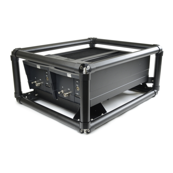
The rigging frame can be used to suspend the coolers from a truss. Content of the kit Pieces Indication Content Top frame Bottom frame Vertical profile A Vertical profile B Rigging screws Eye bolts Bracket front Bracket left Bracket right Safety plate Screw D912 M8 x 16 R5906813 COOLER RIGGING FRAME 13/12/2016... -
Page 6: Necessary Tools
Vertical frames V1 have a fixation hole on one side (1). These vertical frames must be mounted on the bottom frame on the side where the frame has 2 fixation holes on each side (2). Caution: Use high strength threadlocker on the rigging screws thread. Tighten the rigging screws with a torque of 40 Nm. R5906813 COOLER RIGGING FRAME 13/12/2016... - Page 7 2. Place the top frame (F1) onto the rest of the rigging frame. Use the rigging screws (R) to tighten them together. Caution: Use high strength threadlocker on the rigging screws thread. Tighten the rigging screws with a torque of 40 Nm. 40Nm Image 1-3 3. Turn in the 4 eye bolts (E). R5906813 COOLER RIGGING FRAME 13/12/2016...
- Page 8 5. Insert security plate P2 between the 2 brackets P3 and P4. Secure both captive screws. Image 1-6 6. Mount the assembly onto the rigging frame assembly. On each side, drive in the 3 fixation screws. R5906813 COOLER RIGGING FRAME 13/12/2016...
-
Page 9: Mounting The Cooler
Drive in the 4 fixation screws (S). 3. On each side, drive in 1 fixation screws (S). Turn the assembly on its side and turn in the bottom fixation screw (S). Turn the assembly back. Image 1-8 R5906813 COOLER RIGGING FRAME 13/12/2016... - Page 10 Pivot the security plate back and close both captive screws. Image 1-10 Warning: Always close and fixate the security plate! Allowed rigging configuration Overview The following illustrated rigging positions are allowed. Use the gray colored bars to mount the rigging clamps. R5906813 COOLER RIGGING FRAME 13/12/2016...
- Page 11 2. Install the rigging clamps according the measured distance and secure this position. Ensure that the rigging points are symmet- rically lined up, so that the cooler will hang in balance. Warning: Always use four (4) rigging points, equally spread, to suspend the projector. R5906813 COOLER RIGGING FRAME 13/12/2016...
- Page 12 Mount the 2 safety cables around the frame bar (push the hook through the loop and then around the truss so that there is not to much play (maximum 20 cm). If necessary turn the cable a few times around the truss before clasping the safety hook around the cable. R5906813 COOLER RIGGING FRAME 13/12/2016...
- Page 13 Note: Mount the 2 safety cables in such a way that when something goes wrong, the coolers cannot fall more than 20 cm. If necessary, turn the cables a few times around the truss to obtain this maximum distance. 6. Lift up the truss with the attached coolers to the desired height. R5906813 COOLER RIGGING FRAME 13/12/2016...
Need help?
Do you have a question about the Cooler rigging frame and is the answer not in the manual?
Questions and answers