Table of Contents
Advertisement
Quick Links
Advertisement
Table of Contents

Related Manuals for Orbit Merret OM 502


Summary of Contents for Orbit Merret OM 502
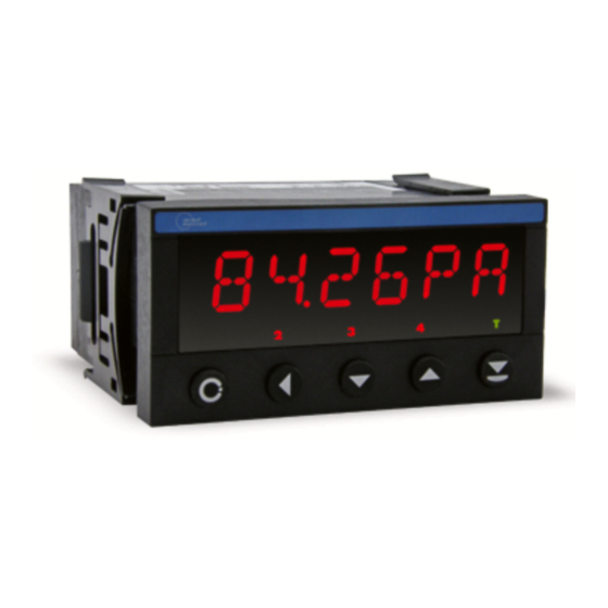
- Page 1 USER MANUAL OM 502 148. 9 ~C 5 DIGIT PROGRAMMABLE INSTRUMENT -263mm DC VOLTMETER/AMMETER PROCESS MONITOR INTEGRATOR LINEARIZATOR 453mV DISPLAYS FOR LINEAR POTENTIOMETERS DISPLAY INSTRUMENT FOR TENSIOMETERS DISPLAYS FOR LVDT SENSORS Outstanding Measurement Value...
- Page 2 The recorder is not designed for installation in potentially explosive surroundings (Ex). Use it only outside potentially explosive surroundings TECHNICAL DATA Measuring instruments of the OM 502 series conform to the European regulation 2014/30/EU and 2014/35/EU The instruments are up to the following European standards EN 61010-1...
-
Page 3: Table Of Contents
6.1.3 Setting the Real Time ....45 6.1.4 External input function selection ..48 6.1.5 Optional accessory functions of the keys . . 49 INSTRUCTIONS FOR USE OM 502 | 3... -
Page 4: Instrument Description
2. INSTRUMENT DESCRIPTION DESCRIPTION The OM 502 model series are 5 digit panel programmable instruments. The instrument is based on 8-bit microcontroller with hight-rate 24-bit sigma-delta converter, which secures high accuracy, stability and easy operation of the instrument. TYPES AND RANGES DC Voltmeter/Ammeter ±999,99 mV;... - Page 5 The operation program is freely accessible (www.orbit.merret.eu) and the only requirement is the purchase of OML cable to connect the instrument to PC. It is manufactured in version RS 232 and USB and is compatible with all ORBIT MERRET instru- ments.
-
Page 6: Instrument Connection
5-6 connect L- to (-) source terminalconnected do not disconnect RS 485 line should have a linear structure - wires (ideally shielded and twisted) should lead from one device to another. 6 | INSTRUCTIONS FOR USE OM 502... -
Page 7: Instrument Connection
Excitation value may be set by trimmer above Grounding on terminal block 3 has to be The “Shielding” and “GND” terminal blocks the terminal block no. 17 connected at all times MUST NOT be connected INSTRUCTIONS FOR USE OM 502 | 7... -
Page 8: Recommended Connection Of Sensors
Sensor (+) Example connection of a 3-wire sensor with current signal output powered by instrument’s excitation INPUT - I Output (+) Supply (+) Output (+) GND (-) 14 15 16 17 Excitation Supply (+) 8 | INSTRUCTIONS FOR USE OM 502... - Page 9 INSTRUMENT CONNECTION 3. Example connection of 3-wire sensor with voltage signal output powered by instrument’s excitation INPUT - U Output (+) Supply (+) Output (+) GND (-) 14 15 16 17 Excitation Supply (+) INSTRUCTIONS FOR USE OM 502 | 9...
-
Page 10: Instrument Setting
Linear menu structure SETTING USER For user operation Menu items are set by the user (Profi/Light) as per request Access is not password protected Optional menu structure either tree (PROFI) or linear (LIGHT) 10 | INSTRUCTIONS FOR USE OM 502... - Page 11 The operation program is freely accessible (www.orbit.merret.eu) and the only requirement is the purchase of OML cable to connect the instrument to PC. It is manufactured in version RS 232 and USB and is compatible with all ORBIT MERRET instru- ments.
-
Page 12: Symbols Used In The Instructions
Setting the minus sign is performed by the key on higher decade. When editing the item substraction must be made from the current number (e.g..: 013 > , on class 100 > -87) 12 | INSTRUCTIONS FOR USE OM 502... -
Page 13: Control Keys Function
SHOW item will not be displayed in USER menu item will be displayed in USER menu with the option of setting SHOW item will be solely displayed in USER menu INSTRUCTIONS FOR USE OM 502 | 13... -
Page 14: Setting "Light" Menu
Linear menu structure Upon delay exceeding 60 s the program- ming mode is automatically discontinued and the instrument itself restores the measuring mode Preset from manufacture Password “0” Menu LIGHT USER menu Setting the items 14 | INSTRUCTIONS FOR USE OM 502... - Page 15 Calibration - only for “DU” C. MIN C. MAX Return to 142. 8 measuring mode Language selection New password Identifi cation Typy of instr. SW version Input LANG. ENGL. OM 502PM PAS. LI. IDENT. 90-001 4-20mA INSTRUCTIONS FOR USE OM 502 | 15...
- Page 16 Set “Password” = 42 Example TYPE Type „DC“ Type “PM” Type „I“ Type „LX“ Type „DU“ Type “T” Type “LVDT” 16 | INSTRUCTIONS FOR USE OM 502...
- Page 17 SETTING LIGHT 5. INSTRUCTIONS FOR USE OM 502 | 17...
-
Page 18: Setting Input - Type "Dc
- range of the setting: ±99999 (-99999…999999) - position of the DP does not affect display = 100 projection Projection for 999,9 mV > MAX A = 3500 Example 0500 1500 2500 3500 FORM. A 18 | INSTRUCTIONS FOR USE OM 502... - Page 19 - positioning of the DP is set here in the measuring = 0000.oo mode Projection of DP on display > 00000.o Example 0000. o o 00000. o MENU *subsequent item on the menu depends on instrument equipment INSTRUCTIONS FOR USE OM 502 | 19...
-
Page 20: Setting Input - Type "Pm
- the DP is automatically shifted after the value is confirmede - range of the setting: ±99999 (-99999…999999) - position of the DP does not affect display projection Projection for 0 mA > MIN A = -25 Example MAX A 20 | INSTRUCTIONS FOR USE OM 502... - Page 21 - positioning of the DP is set here in the measuring = 0000.oo mode Projection of DP on display > 00000.o Example 0000. o o 00000. o MENU *subsequent item on the menu depends on instrument equipment INSTRUCTIONS FOR USE OM 502 | 21...
-
Page 22: Setting Input - Type "I
- the DP is automatically shifted after the value is confirmede - range of the setting: ±99999 (-99999…999999) = 100 Example Projection for 20 mA > MAX A = 2500 0500 1500 2500 SCALE 22 | INSTRUCTIONS FOR USE OM 502... - Page 23 - positioning of the DP is set here in the measuring = 0000.oo mode Projection of DP on display > 00000.o Example *subsequent item on the menu depends on 0000. o o 00000. o MENU instrument equipment INSTRUCTIONS FOR USE OM 502 | 23...
-
Page 24: Setting Input - Type "Lx
- the DP is automatically shifted after the value is confirmede - range of the setting: ±99999 (-99999…999999) = 100 Example Projection for 20 mA > MAX A = 2500 0500 1500 2500 TAB. X 24 | INSTRUCTIONS FOR USE OM 502... - Page 25 - positioning of the DP is set here in the measuring = 0000.oo mode Projection of DP on display > 00000.o Example 0000. o o 00000. o MENU *subsequent item on the menu depends on instrument equipment INSTRUCTIONS FOR USE OM 502 | 25...
-
Page 26: Setting Input - Type "Du
- range of the setting: ±99999 (-99999…999999) - position of the DP does not affect display = 100 projection Projection for the end > MAX A = 5000 Example 0000 1000 2000 3000 4000 5000 FORM. A 26 | INSTRUCTIONS FOR USE OM 502... - Page 27 *subsequent item on the menu depends on 0000. o o 00000. o MENU instrument equipment Calibration of the beginning and the end of range of linear potentiometer is on page 35 INSTRUCTIONS FOR USE OM 502 | 27...
-
Page 28: Setting Input - Type "T
- stable zero (no weight on the scales -stable Menu Measuring mode signal) STAND. Standard - automatic following of zero (eliminates creeping WEIGHT Weighing function over time caused by load cell deformation) Mode “WEIGHT“ Example STAND. WEIGHT MAX A 28 | INSTRUCTIONS FOR USE OM 502... - Page 29 - positioning of the DP is set here in the measuring = 0000.oo mode Projection of DP on display > 00000.o Example 0000. o o 00000. o MENU *subsequent item on the menu depends on instrument equipment INSTRUCTIONS FOR USE OM 502 | 29...
-
Page 30: Setting Input - Type "Lvdt
- gain of input section (it is advisable to use gain GAIN 1 to such a degree when input does not overflow) GAIN 2 = GAIN 1 GAIN 6 GAIN 12 GAIN „GAIN 2“ Example GAIN 1 GAIN 2 MAX A 30 | INSTRUCTIONS FOR USE OM 502... - Page 31 - positioning of the DP is set here in the measuring = 0000.oo mode Projection of DP on display > 00000.o Example 0000. o o 00000. o MENU *subsequent item on the menu depends on instrument equipment INSTRUCTIONS FOR USE OM 502 | 31...
-
Page 32: Setting Limits
Setting limit 2 > L 2 = 53.1 Example 0531 00531 000531 000531. 00053. MENU * subsequent item on the menu depends on instrument equipment Items for “Limits” and “Analog output” are accessible only if incorporated in the instrument. 32 | INSTRUCTIONS FOR USE OM 502... - Page 33 - contingent modification of hysteresis or delay „Hystresis”=0, „Delay”=0 may be performed in “PROFI” menu Setting limit 4 > L 4 = 103 Example * subsequent item on the menu depends MENU on instrument equipment INSTRUCTIONS FOR USE OM 502 | 33...
-
Page 34: Setting Analog Output
Display value for the beginning of the AO range > MIN A.O. = 0 Example MAX A. O . Items for “Limits” and “Analog output” are accessible only if incorporated in the instrument. 34 | INSTRUCTIONS FOR USE OM 502... - Page 35 Assigning the display value to the end of the AO range - range of the setting: -99999…999999 = 100 Display value for the end of the AO range > MAX A.O. = 120 Example MENU INSTRUCTIONS FOR USE OM 502 | 35...
-
Page 36: Selection Of Programming Menu „Light"/„Profi
Type “LX“ Type “DU“ Restoration of manufacture setting > RE. SET. Example Type “T“ RE. SET. TYPE LANG. * subsequent item on the menu depends Type “LVDT“ on instrument equipment 36 | INSTRUCTIONS FOR USE OM 502... -
Page 37: Automatic Calibration - Input Range (Only "Du")
- prior confirming the flashing “YES” sign the potentiometer/sensor traveller has to be in given idle position Calibration of the end of the range > C. MAX Example LANG. INSTRUCTIONS FOR USE OM 502 | 37... -
Page 38: Setting New Access Password
- range of the number code 0…9999 - upon setting the password to “0000” the access to menu LIGHT is free without prompt to enter it New password - 341 > PAS. LI. = 341 Example IDENT. 38 | INSTRUCTIONS FOR USE OM 502... - Page 39 SW number, SW version and current the measuring mode input setting (Mode) - if SW version contains a letter in first position, then it is a customer SW 142. 8 Return to measuring mode INSTRUCTIONS FOR USE OM 502 | 39...
-
Page 40: Setting "Profi" Menu
• password protected access (unless set as follows under the item SERVIC. > N. PASS. > LIGHT =0) • for access to LIGHT menu passwords for LIGHT and PROFI menu may be used 40 | INSTRUCTIONS FOR USE OM 502... - Page 41 SETTING PROFI INSTRUCTIONS FOR USE OM 502 | 41...
-
Page 42: Profi" Menu - Inputs 6.1.1 Resetting Internal Values
(“SUM”) - only for instrument OM 502I CL. MEM. Resetting the instrument memory - resetting memory with data measured in the “FAST” or “RTC” modes - not in standard equipmenthodnoty 42 | INSTRUCTIONS FOR USE OM 502... -
Page 43: Setting Measuring Type, Range, Mode, Rate
2 mV/V CHANNE. KONFIG RANGE 4 mV/V Menu Measuring range 2 mV/V 0,2…4 mV/V OUTPUT. MODE 8 mV/V 4 mV/V 0,4…8 mV/V 8 mV/V. 0,8…16 mV/V SERVIC. EXT. IN. TRACE. 0 KEYS A. ZERO INSTRUCTIONS FOR USE OM 502 | 43... - Page 44 - if stabilized negative value is displayed for a SERVIC. EXT. IN. TRACE. 0 period > 5 s (at active Tare function) the tare is automatically reset KEYS A. ZERO - selection is possible only for mode “WEIGHT” 44 | INSTRUCTIONS FOR USE OM 502...
-
Page 45: Setting The Real Time
Setting the real time clock (RTC) INPUTS CLEAR TIME 00. 0 0. 0 0 Time setting TIME CHANNE. CONFIG. DATE - format 23.59.59 OUTPUT. Date setting DATE SERVIC. EXT. IN. - format DD.MM.YY KEYS INSTRUCTIONS FOR USE OM 502 | 45... - Page 46 000000 00000. o FLOA. P. DESC. I MIN. M AX. INP. M. M . NO CHAN. A FIL. A MAT. FN. LOG. I NO ALL IN OUT 46 | INSTRUCTIONS FOR USE OM 502...
- Page 47 CHAN. A FIL. A MAT. FN. MIN MAX INTEG. BRIGHT 0% 25% 50% 75% 100% Upon delay exceeding 60 s the programming mode is automatically discontinued and the instrument itself restores the measuring mode INSTRUCTIONS FOR USE OM 502 | 47...
-
Page 48: External Input Function Selection
A” after being processed by digital filters MAT. FN. Displaying value of “Mathematical function” EXT. 1 > HOLD EXT. 2 > LOCK K. EXT. 3 > TARE Procedure identical for EXT. 2 and EXT. 3 48 | INSTRUCTIONS FOR USE OM 502... -
Page 49: Optional Accessory Functions Of The Keys
- storing the requested value into the memory after pressing a designated key Clearing memory CL. MEM. Setting is identical for LEFT, DOWN, UP - clearing memory with data measured in modes and ENTER “FAST” or “RTC” INSTRUCTIONS FOR USE OM 502 | 49... - Page 50 Temporary projection of “SUM” (only for OM 502I) Temporary projection of the BRUTO sum of the values of “CHAN. A + TARE + P.TARE” Setting is identical for LEFT, DOWN, UP and ENTER 50 | INSTRUCTIONS FOR USE OM 502...
- Page 51 Direct access to item “OFF 2” OFF 2 OFF 3 Direct access to item “OFF 3” OFF 4 Direct access to item “OFF 4” Setting is identical for LEFT, DOWN, UP and ENTER INSTRUCTIONS FOR USE OM 502 | 51...
- Page 52 SERVIC. MIN. M AX DESC. A = 0.00 LOG. A MAX A Setting display projection for maximum value of input signal - range of the setting is -99999…999999 = 100.00 52 | INSTRUCTIONS FOR USE OM 502...
- Page 53 - when setting (P. TAR. A≠ 0) is in effect, display OUTPUT. INTEGR. FORM. A P. T AR. A does not show the “T” symbol - range of the setting: -99999…999999 SERVIC. MIN. M AX DESC. A LOG. A INSTRUCTIONS FOR USE OM 502 | 53...
- Page 54 (e.g: „CON. F.A“ = 2,5 > display 0, 2.5, 5,…) Setting constants Floating filter CON. F. A Constant F.A = 5.0 - this menu item is always displayed after selection of particular type of filter Exponential filter Constant F.A = 5.0 54 | INSTRUCTIONS FOR USE OM 502...
- Page 55 0…95 SERVIC. MIN. M AX DESC. A - description is cancelled by code 00 LOG. A = none Table of signs on page 85 INSTRUCTIONS FOR USE OM 502 | 55...
- Page 56 Only data measured outside the set interval is stored in memory FROM A Setting the initial interval value - setting range: -99999…999999 Setting the final interval TO A value - setting range: -99999…999999 56 | INSTRUCTIONS FOR USE OM 502...
-
Page 57: Setting Measuring Parameters (Projection, Filters, Decimal Point, Description)
Switching on linearization table - this menu can only be accessed in OM 502LX Setting constants for CON. - calculation of mat.functions - this menu is displayed only after selection of given mathematic function INSTRUCTIONS FOR USE OM 502 | 57... - Page 58 Setting DP - XXX.xxx CON. F Setting DP - XX.xxxx 00. o ooo FORM. M DESC. M Setting DP - X.xxxxx 0. o oooo LOG. M FLOA. P. Floating DP 58 | INSTRUCTIONS FOR USE OM 502...
- Page 59 FORM. M in memory DESC. M Setting the initial interval FROM M LOG. M value - setting range: -99999…999999 TO M Setting the final interval value - setting range: -99999…999999 INSTRUCTIONS FOR USE OM 502 | 59...
-
Page 60: Setting Integrator Parameters
MIN. M AX UNSEN. DIVID. Setting the dividing SUBTR. constant CLEAR - through dividing constant we may further mathematically adjust the data display FORM. I projection - range: 1/10/60/100/1000/3600 DESC. I LOG. I 60 | INSTRUCTIONS FOR USE OM 502... - Page 61 MAT. FN. SCALE integrates onlz in positive values (adds up) OUTPUT. INTEGR. DIVID. Subtraction is off SERVIC. MIN. M AX UNSEN. Subtraction enabled SUBTR. CLEAR FORM. I DESC. I LOG. I INSTRUCTIONS FOR USE OM 502 | 61...
- Page 62 000. o oo Setting DP - XXX.xxx DESC. I Setting DP - XX.xxxx 00. o ooo LOG. I Setting DP - X.xxxxx 0. o oooo FLOA. P. Floating DP 62 | INSTRUCTIONS FOR USE OM 502...
- Page 63 LOG. I in memory Setting the initial interval FROM I value - setting range: -99999…999999 TO I Setting the final interval value - setting range: -99999…999999 INSTRUCTIONS FOR USE OM 502 | 63...
-
Page 64: Selection Of Evaluation Of Min/Max. Value
FIL. A Evaluation of min/max value is off SERVIC. MIN. M AX MAT. FN. From “Channel A” CHAN. A FIL. A From “Channel A” after digital filters processing MAT. FN. From “Mathematic functions” 64 | INSTRUCTIONS FOR USE OM 502... - Page 65 SETTING PROFI INSTRUCTIONS FOR USE OM 502 | 65...
-
Page 66: Profi" Menu - Output 6.3.1 Setting Data Logging
- selection of the mode in the event of full instrument memory CHANNE. LIMITS START Rewriting values prohibited OUTPUT. DATA STOP SERVIC. AN. OUT. PERIOD. Rewriting values permitted, the oldest get rewritten by DISP. TRIGER the latest 66 | INSTRUCTIONS FOR USE OM 502... - Page 67 A new recording is possible after the deletion of the latest recording. It is possible to abort a recording before its completion 3 . Termination by reading out the data. - ext. input, button or reading data via RS INSTRUCTIONS FOR USE OM 502 | 67...
-
Page 68: Setting Limits
Z < 0 - Switch-on relay TYPE > SWITCH-OFF LED signalization Z > 0 - Switch-off relay TYPE > SWITCH-ON LED signalization Z < 0 - Switch-off relay TYPE > SWITCH-OFF LED signalization 68 | INSTRUCTIONS FOR USE OM 502... - Page 69 “TIM. L.2” indicating the time during which is the output active Setting is identical for LIM 1, LIM 2, LIM 3 and LIM 4 INSTRUCTIONS FOR USE OM 502 | 69...
- Page 70 - negative time > relay switches off after crossing the limit (LIM. L1) and the set negative time (TIM. L.1) Setting is identical for LIM 1, LIM 2, LIM 3 and LIM 4 70 | INSTRUCTIONS FOR USE OM 502...
-
Page 71: Setting Data Output
- MODBUS SERVIC. AN. OUT. ADR. P. B . - setting in range 1…247 DISP. PROT. Setting instrument address ADR. P. B . - PROFIBUS - setting in range 1…127 = 19 INSTRUCTIONS FOR USE OM 502 | 71... -
Page 72: Setting Analog Output
AO evaluation from FIL. A “Channel A” after digital filters processing INTEG. AO evaluation from “Math. MAT. FN. functions” AO evaluation from “Min. value” AO evaluation from “Max. value” INTEG. AO evaluation from “Integrated value” 72 | INSTRUCTIONS FOR USE OM 502... - Page 73 DISP. AO range - range of the setting: -99999…999999 MAX A. O . Assigning the display value to the end of the AO range - range of the setting: -99999…999999 = 100 INSTRUCTIONS FOR USE OM 502 | 73...
-
Page 74: Selection Of Display Projection
- after keystroke display turns on for 10 s DISP. Display brightness - 25 % Display brightness - 50 % Display brightness - 75 % 100% Display brightness - 100 % 74 | INSTRUCTIONS FOR USE OM 502... - Page 75 SETTING PROFI INSTRUCTIONS FOR USE OM 502 | 75...
-
Page 76: Light"/„Profi
- linear menu > items one after another IDENT. Active PROFI menu PROFI - complete programming menu for expert users - tree menu Change of setting is valid upon next access into menu 76 | INSTRUCTIONS FOR USE OM 502... -
Page 77: Restoration Manufacture Setting
After restoration the instrument switches off deletes data stored in FLASH for couple seconds cancels or linearization tables clears tare restore manufacture calibration restore manufacture setting INSTRUCTIONS FOR USE OM 502 | 77... -
Page 78: Automatic Calibration - Input Range
CHANNE. RESTOR. C. MAX. - item is availale after aut. calibration Minimum calibration range OUTPUT. CALIB. EDIT SERVIC. LANG. - range: ±99.0000 Maximum calibration range N. PASS. - range: ±99.0000 IDENT. 78 | INSTRUCTIONS FOR USE OM 502... -
Page 79: Instrument Identification
- if the SW version reads a letter on first position, OUTPUT. CALIB. it is a customer SW SERVIC. LANG. Pos. Description N. PASS. type of instrument SW: number - version IDENT. the input type INSTRUCTIONS FOR USE OM 502 | 79... -
Page 80: Setting Items Into "User" Menu
return to item SHOW item will not be displayed in USER menu item will be displayed in USER menu with editing option SHOW item will be solely displayed in USER menu 80 | INSTRUCTIONS FOR USE OM 502... - Page 81 Limit one. You can exit the setting by pressing the button by which you store the latest setting and pressing the button will take you back to the measuring mode INSTRUCTIONS FOR USE OM 502 | 81...
-
Page 82: Data Protocol
(D) (D) (D) (D) (D) <ETX> <BCC> Command confirmation (instrument) <CR> <CR> Messbus No - data is transmitted permanently <CR> <CR> <DLE> <NAK> Instrument identification <CR> HW identification <CR> One-time transmission <CR> Repeated transmission <CR> 82 | INSTRUCTIONS FOR USE OM 502... - Page 83 Confirm error statement format >HH <CR>, where HH is value in HEX format and range 00 …FF . The lowest bit stands for „Relay <BCC> Check sum -XOR 1“, the highest for „Relay 8“ INSTRUCTIONS FOR USE OM 502 | 83...
-
Page 84: Error Statements
E. CLR Memory was empty (presetting carried out) possible failure in calibration E. . OUT. Analogue output current loop disconnected check wire connection 84 | INSTRUCTIONS FOR USE OM 502... -
Page 85: Table Of Symbols
0 to 95. Numeric value of given character equals the sum of the numbers on both axes of the table. Description is cancelled by entering characters with code 00 INSTRUCTIONS FOR USE OM 502 | 85... -
Page 86: Technical Data
1…4 / 2…8 / 4…16 mV/V Connection: 4/6-wire Tensiometer volt.: 10 VDC, max. load 65 Ω Connection: 3/5-wire LVDT Gain: 1x/2x/6x/12x Power supply: 1/3/5 VAC with frequency 2,5/5/10 kHz * values apply for resistance load 86 | INSTRUCTIONS FOR USE OM 502... - Page 87 > 670 V (PI), 300 V (DI) Input/output > 300 V (PI), 150 (DI) EXCITATION EMC: EN 61326-1 Adjustbale: 5…24 VDC/max. 1,2 W, isolated Fixed: 10 VDC, maximal load is 65 Ω PI - Primary insulation, DI - Double insulation INSTRUCTIONS FOR USE OM 502 | 87...
-
Page 88: Instrument Dimensions And Instalation
3. press the travellers close to the panel INSTRUMENT DISASSEMBLY 1. slide a screw driver under the traveller wing 2. turn the screw driver and remove the traveller 3. take the instrument out of the panel 88 | INSTRUCTIONS FOR USE OM 502... -
Page 89: Certificate Of Guarantee
- unavoidable event unavoi - other unprofessional interventions other un The manufacturer performs guarantee and post.guarantee repairs unless provided for otherwise. rms guarantee and post.guara for otherwise. Stamp, signature Stamp Y E A R S INSTRUCTIONS FOR USE OM 502 | 89... - Page 90 ORBIT MERRET, spol.s r.o. and that our company has taken all measures to ensure conformity of all products of the types referred-to hereunder, which are being brought out to the market, with technical documentation and requirements of the appurtenant Czech statutory orders.
- Page 91 ORBIT MERRET, spol. s r. o. Vodňanská 675/30 198 00 Praha 9 Czech Republic tel.: +420 281 040 200 fax.: +420 281 040 299 orbit@merret.eu www.orbit.merret.eu TECHDOK - OM 502 - 2019 - 4v0 - en...
Need help?
Do you have a question about the OM 502 and is the answer not in the manual?
Questions and answers