
Subscribe to Our Youtube Channel
Related Manuals for Orbit Merret OM 601UQC


Summary of Contents for Orbit Merret OM 601UQC
- Page 1 GUARANTEE OM 601UQC 6 DIGIT PROGRAMMABLE IMPULSE COUNTER FREQUENCY-/PHASE-/PERIOD-METER STOP-WATCH/WATCH...
- Page 2 INSTRUCTIONS FOR USE OM 601UQC SAFETY INSTRUCTIONS Please, read the enclosed safety instructions carefully and observe them! These instruments should be safeguarded by isolated or common fuses (breakers)! For safety information the EN 61 010-1 + A2 standard must be observed.
-
Page 3: Table Of Contents
1. CONTENTS CONTENTS Contents ..................3 Instrument description . -
Page 4: Instrument Description
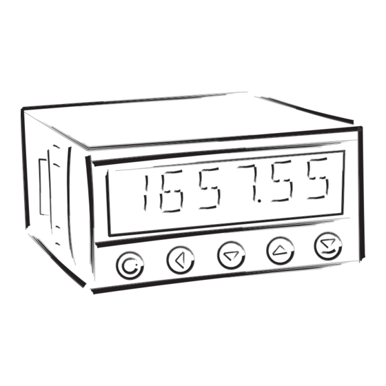
INSTRUCTIONS FOR USE OM 601UQC INSTRUMENT DESCRIPTION DESCRIPTION The OM 601UQC model is a universal 6 digit programmable panel impulse counter/frequency meter/repeat/stop- watch. The instrument is based on an 8-bit microprocessor, that secures high accuracy, stability and easy operation of the instrument. - Page 5 2. INSTRUMENT DESCRIPTION OPERATION The instrument is set and controlled by five control keys located on the front panel. All programmable settings of the instrument are realised in two adjusting modes: Configuration menu (hereinafter referred to as „CM“) is protected by an optional numeric code and contains complete instrument setting User menu may contain arbitrary programming setting defined in CM with another selective restriction...
-
Page 6: Connection
INSTRUCTIONS FOR USE OM 601UQC CONNECTION The supply lead for feeding the instrument should not be in the proximity of low-potential signals. Contactors, motors with larger input and other efficient elements should not be in the proximity of the instrument. -
Page 7: Setting The Jumpers
3. INSTRUMENT CONNECTION 3.1 CONFIGURATION OF THE JUMPERS Setting the comparator levels Excitation J1 J2 J3 J1 - Input "A" J2 - Input "B" J3 - Input "Reset, C" J4 - Excitation 1 - 2, 3 - 4 2...9 V 2 - 3, 4 - 5 9...12 V 1 - 2, 4 - 5... -
Page 8: Setting
INSTRUCTIONS FOR USE OM 601UQC INSTRUMENT SETTING The instrument is set and controlled by 5 control keys located on the front panel. By means of these control keys it is possible to browse through the operating program, to select and set the required values. -
Page 9: Setting The Dp And The (-) Sign
4. INSTRUMENT SETTING SETTING THE DECIMAL POINT AND THE MINUS SIGN DECIMAL POINT Upon modification of the edited number in the menu the decimal point is set by key with transition beyond the highest decade, when the decimal point starts flashing. Positioning is performed by , and confirmation by with return into number editing. -
Page 10: Minimum Instrument Setting
INSTRUCTIONS FOR USE OM 601UQC MINIMUM INSTRUMENT SETTING All settings are performed in the „Configuration menu“ Presetting values in the menu Return to manufacture SETTIN. setting INPUTS ACCESS CALIB. FREQV. - reading the manufacture calibration and basic setting of items in the menu (DEF) CHANNE. - Page 11 4. INSTRUMENT SETTING - CONFIGURATION MODE Setting display projection Setting basic parameters SET. A of channel A INPUTS CHAN. A INP. A CONST. Calibration constant CONST. . CHANNE. CHAN. B OFFSET - calibration constant is for the conversion of OUTPUT MATH.
-
Page 12: Values Resetting (Counters, Total, Min/Max, Tare)
INSTRUCTIONS FOR USE OM 601UQC USER MENU • designated for instrument service • may contain setting the limits, analog data output and brightness, with restriction as per the setting in "Configuration mode" 23. 6 INPUTS INPUTS CLEAR CONFIG. Setting the instrument input... -
Page 13: User Mode
4. INSTRUMENT SETTING - USER MODE 4.2.1.2 TIME SETTING Time setting, mode „Stop- SET. T watch“ with RTC INPUTS CLEAR SET. T - after setting the time in format HH.MM.SS OUTPUT CONFIG (set after pressing „ENTER“) next is set the date in format DD.MM.YY, confirmation is made by pressing „ENTER“... -
Page 14: Setting The Analog Output
INSTRUCTIONS FOR USE OM 601UQC 4.2.2.3 DATA OUTPUT - SETTING THE RATE Setting the data output BAUD rate (baud) INPUTS LIMIT BAUD Rate - 600 Baud OUTPUT DATA ADDR. 1200. Rate - 1 200 Baud 1200 AN. OUT. 2400 DISP 4800. -
Page 15: Projection Of Data On The Display
4. INSTRUMENT SETTING - CONFIGURATION MODE 4.2.2.5 PROJECTION OF DATA ON THE DISPLAY In this menu item the SHOW following data may be displayed INPUTS LIMIT SHOW CHAN. A OUTPUT DATA SETTIN. CHAN. B Value of „Channel A“ CHAN. A AN. - Page 16 INSTRUCTIONS FOR USE OM 601UQC CONFIGURATION MENU • designated for professional service and maintenance • complete instrument setting • the access is password protected • authorization for "User mode" SERVICE > A Channel A DISPLAY > FIL. A > B FILTER RELAYS >...
-
Page 17: Configuration Mode - Input
4. INSTRUMENT SETTING - CONFIGURATION MODE 4.3.1 CONFIGURATION MODE - INPUTS Here the basic instrument parameters are set INPUTS CLEAR Resetting the internal CLEAR values CHANNE. CONFIG Basic instrument setting CONFIG OUTPUT AUX. I NP. Setting the „Hold“ function AUX. I NP. . SERVIC. -
Page 18: Instrument Configuration
INSTRUCTIONS FOR USE OM 601UQC 4.3.1.2 INSTRUMENT CONFIGURATION Basic instrument setting CONFIG INPUTS CLEAR M. MODE Setting the instrument M. MODE CHANNE. CONFIG M. TIME measuring mode Setting the time of M. TIME OUTPUT AUX. I NP. SET. T measurement - time base SERVIC. - Page 19 4. INSTRUMENT SETTING - CONFIGURATION MODE 4.3.1.2.2 SETTING THE TIME OF MEASUREMENT/TIME BASE Setting the time of M. TIME measurement - time base INPUTS CLEAR M. MODE 50 ms - if you set the time of measurement for example CHANNE. CONFIG M.
- Page 20 INSTRUCTIONS FOR USE OM 601UQC 4.3.1.2.4 SETTING THE STOP-WATCH/WATCH CONTROL Setting the stop-watch M. START control INPUTS CLEAR M. MODE CONTIN Stop-watch/watch is CONTIN running, if the instrument CHANNE. CONFIG M. TIME CONTAC. is on OUTPUT AUX. I NP. SET. T...
- Page 21 5. INSTRUMENT SETTING - CONFIGURATION MODE 4.3.1.2.6 SETTING THE ZEROIZING INPUT Setting the zeroizing input M. CLR INPUTS CLEAR M. MODE COUNT A - setting zeroizing input (input C) and key with CHANNE. CONFIG M. TIME COUNT B assigned resetting function OUTPUT AUX.
- Page 22 INSTRUCTIONS FOR USE OM 601UQC 4.3.1.2.8 SETTING THE PRE-DIVISION CONSTANT Setting the pre-division DIVID. constant INPUTS CLEAR M. MODE - the pre-division constant serves to enlarge the CHANNE. CONFIG M. TIME calibration constant range OUTPUT AUX. I NP. SET. T Pre-division constant =1 SERVIC.
-
Page 23: Auxiliary Inputs
4. INSTRUMENT SETTING - CONFIGURATION MODE 4.3.1.2.10 SETTING THE INPUT FILTER PARAMETERS Setting the input M. M . INP. „quantity“ for evaluation of the min/max. value INPUTS CLEAR M. MODE DISABL. CHANNE. CONFIG M. TIME CHAN. A Min/max value is DISABL. -
Page 24: 4.3.2 Configuration Mode - Channels
INSTRUCTIONS FOR USE OM 601UQC 4.3.2 CONFIGURATION MODE - CHANNELS Here the basic parameters of the instrument input values are set INPUTS CHAN. A Setting the parameters and CHAN. A range of the meas. channel CHANNE. CHAN. B Setting the parameters and CHAN. - Page 25 4. INSTRUMENT SETTING - CONFIGURATION MODE 4.3.2.1.2 SETTING THE TIME BACKUP Setting the RTC circuit - time backup INPUTS CHAN. A INP. A DISABL. RTC circuit is switched off DISABL. CHANNE. CHAN. B TIME RTC controls the internal OUTPUT MATH. F N. SET.
- Page 26 INSTRUCTIONS FOR USE OM 601UQC 4.3.2.1.4 FUNCTIONS UPON READING THE DISPLAY/VALUE Setting the instrument MI. MA. status when reading the display INPUTS CHAN. A INP. A MI. MA. CLEAR CHANNE. CHAN. B VAL. M. STOP The instrument is CLEAR automatically set to zero OUTPUT MATH.
- Page 27 4. INSTRUMENT SETTING - CONFIGURATION MODE 4.3.2.1.6 SETTING THE DIGITAL FILTERS Setting the digital filters F. M OD. 1 INPUTS CHAN. A INP. A F. MOD1 DISABL. - into the filter enter values adjusted from CHANNE. CHAN. B CONST. F EXPON.
- Page 28 INSTRUCTIONS FOR USE OM 601UQC 4.3.2.1.7 PROJECTION FORMAT Setting the projection FORMAT format for Channel A INPUTS CHAN. A INP. A 000000 - the instrument enables projection of a number CHANNE. CHAN. B 00000. 0 with decimal positioning of the decimal point...
-
Page 29: Mathematic Operations And Functions
4. INSTRUMENT SETTING - CONFIGURATION MODE 4.3.2.2.1 MATHEMATIC OPERATIONS BETWEEN THE INPUTS Selection of mathematic operations between inputs A and B INPUTS CHAN. A CHANNE. CHAN. B MATH. F Mathematic operations between inputs are off OUTPUT MATH. F N. CONST. A Mathematic functions will be SERVIC. - Page 30 INSTRUCTIONS FOR USE OM 601UQC 4.3.2.2.3 MATHEMATIC FUNCTIONS - PROJECTION FORMAT Setting the format of FORMAT projection on display for „MATH.FN“ INPUTS CHAN. A MAT. F 000000 CHANNE. CHAN. B CONST. A 00000. 0 - the instrument enables classic projection of...
-
Page 31: 4.3.3 Configuration Mode - Output
4. INSTRUMENT SETTING - CONFIGURATION MODE 4.3.3 CONFIGURATION MODE - OUTPUT Setting the functions LIMIT and type of limits switch-on INPUTS LIMIT Setting the type and DATA parameters of data output CHANNE. DATA Setting the type and AN. OUT. parameters of analog output OUTPUT AN. - Page 32 INSTRUCTIONS FOR USE OM 601UQC 4.3.3.1.2 LIMITS - SETTING THE TYPE OF LIMITS Setting the type of limits TYPE. L INPUTS LIMIT LIM 1 INP. L. HYSTER. The limit has a boundary, HYSTER CHANNE. DATA LIM 2 TYPE. L. FROM hysteresis and delay - for this regime we set the parameters „LIMIT“,...
-
Page 33: Data Output
4. INSTRUMENT SETTING - CONFIGURATION MODE 4.3.3.1.4 LIMITS - SETTING THE BOUNDARIES Setting the values for LIM - limits evaluation INPUTS LIMIT LIM 1 INP. L. Setting limit for relay LIMIT CHANNE. DATA LIM 2 TYPE. L. switch on - in full display range OUTPUT AN. -
Page 34: Analog Output
INSTRUCTIONS FOR USE OM 601UQC 4.3.3.2.2 DATA OUTPUT - SETTING THE INSTRUMENT ADDRESS Setting the instrument ADDR. address INPUTS LIMIT BAUD - setting in the range of 0…31 CHANNE. DATA ADDR. - manufacture setting 00 OUTPUT AN. OUT. PROT. SERVIC. - Page 35 4. INSTRUMENT SETTING - CONFIGURATION MODE 4.3.3.3.2 ANALOG OUTPUT - SETTING THE TYPE Setting the type of analog A. O. TYPE output INPUTS LIMIT A. O. INP. 0-20mA - current and voltage outputs are galvanically CHANNE. DATA A. O. T YPE 4-20mA separated Output: 0…20 mA...
-
Page 36: Projection On The Display
INSTRUCTIONS FOR USE OM 601UQC 4.3.3.4 PROJECTION ON THE DISPLAY In this menu item the SHOW following data may be projected INPUTS LIMIT SHOW CHAN. A CHANNE. DATA SETTIN. CHAN. B Value of „Channel A“ CHAN. A OUTPUT AN. OUT. - Page 37 4. INSTRUMENT SETTING - CONFIGURATION MODE 4.3.3.4.2 DISPLAY PROJECTION - AFTER PRESSING „LEFT“ Setting the functions of key „LEFT“ - INPUTS LIMIT SHOW FOREV. DISABL. CHANNE. DATA SETTIN. CL. C. A . The key is inactive DISABL. OUTPUT AN. OUT. TEMPOR.
- Page 38 INSTRUCTIONS FOR USE OM 601UQC Direct access to selected MENU menu item INPUTS LIMIT SHOW SHOW LIMIT 1 - the item is accessible after its setting in menu CHANNE. LIMIT2 DATA SETTIN. „KEY“ > „MENU“ OUTPUT AN. OUT. TEMPOR. A. C ONST.
- Page 39 4. INSTRUMENT SETTING - CONFIGURATION MODE 4.3.3.4.4 DISPLAY PROJECTION - AFTER PRESSING THE KEY „ENTER“ Assigning function to the ENTER key „ENTER“ INPUTS LIMIT SHOW FOREV. The key has no function CHANNE. DATA SETTIN. TARA Display taring OUTPUT AN. OUT. TEMPOR.
-
Page 40: Access Rights For User Mode
INSTRUCTIONS FOR USE OM 601UQC 4.3.4 CALIBRATION MODE - SERVICE Setting the access rights for ACCESS „User mode“ INPUTS ACCESS Return to manufacture RESTOR. calibration or setting CHANNE. RESTOR. Instrument calibration CALIB OUTPUT CALIB Setting the language version LANG. SERVIC. - Page 41 4. INSTRUMENT SETTING - CONFIGURATION MODE 4.3.4.1.2 SETTING THE ACCESS RIGHTS FOR „USER MODE“ - LIMITS Setting the access rights A. LIM x into Limits in the „UM“ INPUTS ACCESS A. CLR LIMIT DISABL Authorization for item LIMIT CHANNE. RESTOR. A.
- Page 42 INSTRUCTIONS FOR USE OM 601UQC 4.3.4.1.4 SETTING THE ACCESS RIGHTS FOR „USER MODE“ - PROJECTION Authorization for A. SHOW temporary projection of internal values „SHOW“ from menu INPUTS ACCESS A. CLR DISABL. „OUTPUT - DISP“ CHANNE. RESTOR. A. LIM 1...
-
Page 43: Return To Manufacturing Calibration/Setting
4. INSTRUMENT SETTING - CONFIGURATION MODE 4.3.4.2 RETURN TO MANUFACTURE CALIBRATION/SETTING Return to manufacture RESTOR. calibration and INPUTS ACCESS CALIB. YES? instrument setting CHANNE. RESTOR. SETTIN. - in case of incorrect setting or calibration it is possible to return to manufacture setting. Prior OUTPUT CALIB execution of the changes you will be asked to... -
Page 44: Instrument Menu Language
INSTRUCTIONS FOR USE OM 601UQC 4.3.4.4 LANGUAGE VERSION FOR THE INSTRUMENT MENU Setting the language LANG. version of the instrument menu INPUTS ACCESS CZECH CHANNE. RESTOR. ENGL. The instrument menu is in CZECH Czech language OUTPUT CALIB The instrument menu is in ENGL. -
Page 45: Table Of Symbols
5. TABLE OF SYMBOLS TABLE OF SYMBOLS The instrument allows to add two descriptive characters to the classic numeric formats (at the expense of the number displayed places). The setting is performed by means of a shifted ASCII code. Upon modification the first two places display the entered characters and the last two places the code of the relevant symbol from 0 to 95. -
Page 46: Data Protocol
INSTRUCTIONS FOR USE OM 601UQC DATA PROTOCOL The instruments communicate via serial line RS232 or RS485. For communication they use either ASCII protocol or DIN MessBus protocol. The communication is running in the following format: ASCII: 8 bit, no parity, one stop bit... -
Page 47: Error Statements
7. ERROR STATEMENTS 7. ERROR STATEMENTS ERROR REASON ELIMINATION E. UND change the input signal value range underfl ow (A/D converter) or change display projection E. OVER change the input signal value range overfl ow (A/D converter) or change display projection E. -
Page 48: Technical Data
INSTRUCTIONS FOR USE OM 601UQC TECHNICAL DATA INPUT DATA OUTPUTS Type: upon contact, TTL, NPN/PNP Protocols: DIN MESSBUS; ASCII Measurements: 1x counter/freq./repeat/phase UP or DOWN Data format: 7 bit + even parity + 1 stop bit (DIN MESSBUS) 2x counter/frequency UP nebo DOWN... -
Page 49: Instrument Dimensions And Installation
9. INSTRUMENT DIMENSIONS AND INSTALATIONS INSTRUMENT DIMENSIONS AND INSTAL. Front view Panel cut 96 mm 90,5 mm Side view 119 mm 13,5 mm Panel thickness: 0,5...20 mm Instrument installation 1. insert the instrument into the panel cut-out 2. fit both travellers on the box 3. -
Page 50: Declarations Of Conformity
ORBIT MERRET, spol.s r.o. and that our company has taken all measures to ensure conformity of all products of the type listed hereunder, which are being brought out to the market, with technical documentation and requirements of the appurtenant statutory orders. -
Page 51: 11. Certificate Of Guarantee
11. CERTIFICATE OF GUARANTEE 11. CERTIFICATE OF GUARANTEE Product OM 601UQC Type ....Manufacturing No..... - Page 52 METRIX Instruments Co. 1711 Townhurst Dr. Houston, Texas 77043-2899 tel: +1 - 713 - 461 21 31 fax: +1 - 713 - 461 82 83 e-mail: sales@metrix1.com www.metrix1.com TECHDOK - OM 601UQC - 2003 - v.5.50 - e...
Need help?
Do you have a question about the OM 601UQC and is the answer not in the manual?
Questions and answers