Table of Contents
Advertisement
Quick Links
Advertisement
Table of Contents

Related Manuals for Orbit Merret OM 402UNI


Summary of Contents for Orbit Merret OM 402UNI
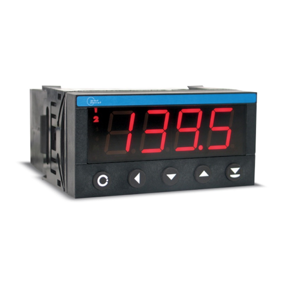
- Page 1 G U A R A N T E E Y E A R S OM 402UNI 20 mm 4 DIGIT PROGRAMMABLE UNIVERSAL INSTRUMENT DC VOLTMETER/AMMETER PROCESS MONITOR OHMMETER THERMOMETER FOR PT 100/500/1 000 THERMOMETER FOR NI 1 000 THERMOMETER FOR THERMOCOUPLES DISPLAYS FOR LIN. POTENTIOMETERS...
- Page 2 IEC 980: 1993, čl. 6 The instruments are applicable for unlimited use in agricultural and industrial areas. CONNECTION Supply of energy from the main line has to be isolated from the measuring leads. ORBIT MERRET, spol. s r.o. Vodnanska 675/30 198 00 Prague 9 Czech Republic Tel: +420 - 281 040 200...
-
Page 3: Table Of Contents
CONTENTS 1. CONTENTS ....... . 3 6.2 “PROFI” menu - CHANNEL 6.2.1 Setting measuring parameters (projection, filters, 2. -
Page 4: Instrument Description
Two models are available: UNI and PWR. Type OM 402UNI is a multifunction instrument with the option of configuration for 8 various input options, easily configurable in the instrument menu. By further options of input modules it is feasible to measure larger ranges of DC voltage and current or increase the number of inputs up to 4 (applies for PM). - Page 5 OML cable to connect the instrument to PC. It is manufactured in version RS 232 and USB and is compatible with all ORBIT MERRET instruments. Another option for connection is with the aid of data output RS 232 or RS 485 (without the need of the OML cable).
-
Page 6: Instrument Connection
3. INSTRUMENT CONECTION The instrument supply leads should not be in proximity of the incoming low-potential signals. Contactors, motors with larger input power should not be in proximity of the instrument. The leads into the instrument input (measured quantity) should be in sufficient distance from all power leads and appliances. Provided this cannot be secured it is necessary to use shielded leads with connection to ground (bracket E). -
Page 7: Instrument Connection
INSTRUMENT CONECTION Excitation has the minus pole common with the input - the bracket no. 20 - GND and Open collectors you may set its value by trimmer above the bracket no. 17 Relays Option A RxD/L+ INPUT - U TxD/L- 11 12 13 GND - U/I0,5... - Page 8 3. INSTRUMENT CONECTION Example connection of a 2-wire sensor with current signal output powered by instrument’s excitation 14 15 16 17 18 19 20 21 Excitation INPUT - I Sensor (+) Sensor (-) Example connection of a 3-wire sensor with current signal output powered by instrument’s excitation Supply (+) Output (+) GND (-)
- Page 9 INSTRUMENT CONECTION 3. Example connection of 3-wire sensor with voltage signal output powered by instrument’s excitation Supply (+) Output (+) GND (-) 14 15 16 17 18 19 20 21 Excitation INPUT - U Supply (+) Output (+) Example connection of resistance measurement using 4 wires By connecting resistor R* we elimintate error message E.
-
Page 10: Instrument Setting
4. INSTRUMENT SETTING SETTING PROFI For expert users Complete instrument menu Access is password protected Possibility to arrange items of the USER MENU Tree menu structure SETTING LIGHT For trained users Only items necessary for instrument setting Access is password protected Possibility to arrange items of the USER MENU Linear menu structure SETTING... - Page 11 The operation program is freely accessible (www.orbit.merret.eu) and the only requirement is the purchase of OML cable to con- nect the instrument to PC. It is manufactured in version RS 232 and USB and is compatible with all ORBIT MERRET instruments.
-
Page 12: Symbols Used In The Instructions
4. INSTRUMENT SETTING Setting and controlling the instrument is performed by means of 5 control keys located on the front panel. With the aid of these keys it is possble to browse through the operation menu and to select and set required values. Measured value (red/green/orange LED) Ralay status... -
Page 13: Control Keys Function
INSTRUMENT SETTING 6. Control keys functions MEASUREMENT MENU SETTING NUMBERS/SELECTION access into USER menu exit menu quit editing programmable key function back to previous level move to higher decade programmable key function move to previous item move down programmable key function move to next item move up programmable key function... -
Page 14: Setting "Light" Menu
5. SETTING LIGHT SETTING LIGHT For trained users Only items necessary for instrument setting Access is password protected Possibility to arrange items of the USER MENU Linear menu structure 14 | INSTRUCTIONS FOR USE OM 402UNI_20... - Page 15 SETTING LIGHT 5. Access password 142. 8 PASS. Type of instruments Measuring range TYPE MODE 4-20mA Selecting projection and connection CON. 2-W. FOR. A 000. o CON. EXT. 1 C. J. T . FOR. A 0000 MIN. A MAX. A FOR.
- Page 16 5. SETTING LIGHT 142. 8 Entering access password PASS. for access into the menu PASS. Access into instrument menu PASS. > 0 PASS. = 0 - access into menu is protected ny number code - access into menu is unrestricted, after releasing keys you automaticaly move to first item of the menu Ser „PASS.“=42...
- Page 17 SETTING LIGHT 5. INSTRUCTIONS FOR USE OM 402UNI_20 | 17...
- Page 18 SETTING LIGHT 1200 MODE MODE Selection of the instrument measuring range Menu Measuring range ±60 mV = 60 mV ±150 mV ±300 mV 1200 ±1,2 V = 500 V* ±100 V ±250 V * only for option “A” ±500 V 0.10 ±0,1 A...
- Page 19 SETTING LIGHT MAX. A Setting for maximum input signal MAX. A Setting display projection for maximum value of input - the DP is automatically shifted after the value is signal confirmed - range of the setting: -999…9999 - position of the DP does not affect display = 100 projection...
- Page 20 SETTING LIGHT MODE i0-5 0-20 4-20 0- 10 0-40 Er. 4 • • • MODE Selection of the instrument measuring range Menu Measuring range i0-5 0…5 mA 0-20 0…20 mA 4-20 4…20 mA = 4 - 20 mA u0-2 ±2 V u0-5...
- Page 21 SETTING LIGHT MAX. A Setting for maximum input signal MAX. A Setting display projection for maximum value of input signal - the DP is automatically shifted after the value is confirmed - range of the setting: -999…9999 - position of the DP does not affect display projection = 100...
- Page 22 5. SETTING LIGHT 0. 1 1. 0 10. 0 100. 0 AUTO MODE MODE Selection of the instrument Menu Measuring range measuring range 0…100 Ω 0…1 kΩ 10.0 0…10 kΩ = 100 Ω 100.0 0…100 kΩ AUTO Autorange Range 0…10 kΩ...
- Page 23 SETTING LIGHT 5. MAX. A Setting for maximum input signal MAX. A Setting display projection for maximum value of input signal - the DP is automatically shifted after the value is confirmed - range of the setting: -999…9999 - position of the DP does not affect display projection = 100...
- Page 24 SETTING LIGHT EU0. 1 EU0. 5 EU1. 0 US0. 1 R. 50 R. 1 00 MODE MODE Selection of the instrument measuring range Menu Measuring range EU0.1 Pt 100 (3 850 ppm/°C) = Pt 100 EU0.5 Pt 500 (3 850 ppm/°C) EU1.0 Pt 1000 (3 850 ppm/°C) US0.1...
- Page 25 SETTING LIGHT FOR. A 0000 000. o 00. o o FOR. A Setting projection of the decimal point - positioning of the DP is set here in the measuring = 000.o mode Projection of DP on display > 0000 Example 000.
- Page 26 SETTING LIGHT 5- 1 6- 1 5- 10 6- 10 MODE MODE Selection of the instrument measuring range Menu Measuring range Ni 1 000 (5 000 ppm/°C) = Ni 1 000 - 5 000 ppm/°C Ni 1 000 (6 180 ppm/°C) 5-10 Ni 10 000 (5 000 ppm/°C) 6-10...
- Page 27 SETTING LIGHT FOR. A 0000 000. o 00. o o FOR. A Setting projection of the decimal point - positioning of the DP is set here in the measuring = 000.o mode Projection of DP on display > 0000 Example 000.
- Page 28 SETTING LIGHT TC B TC E TC J TC K > MODE TC N TC R TC S TC T TC L > MODE Selection of the type of thermocouple Menu Type of thermocouple tC B tC E = Type “J”...
- Page 29 SETTING LIGHT C. J. T . Setting temperature of cold junction C. J. T . Setting temperature of cold junction - range 0…99°C with compensation box = 23 Setting temperature of cold junction > C. J.t. = 35 Example FOR.
- Page 30 SETTING LIGHT MIN. A Setting for minimum input signal MIN. A Setting display projection for minimum value of input signal - the DP is automatically shifted after the value is confirmed - range of the setting: -999…9999 - position of the DP does not affect display projection Projection for the beginning >...
- Page 31 SETTING LIGHT FOR. A 0000 000. o 00. o o 0. o o o FL. P. FOR. A Setting projection of the decimal point - positioning of the DP is set here in the measuring = 000.o mode Projection of DP on display >...
- Page 32 SETTING LIGHT 8-50 8-0. 1 6-50 6-0. 1 MODE MODE Selection of the instrument measuring range Menu Measuring range = Cu 50 (4 285 ppm/°C) 8-50 Cu 50 (4 285 ppm/°C) 8-0.1 Cu 100 (4 285 ppm/°C) 6-50 Cu 50 (4 260 ppm/°C) 6-0.1...
- Page 33 SETTING LIGHT FOR. A 0000 000. o 00. o o FOR. A Setting projection of the decimal point - positioning of the DP is set here in the measuring = 000.o mode Projection of DP on display > 0000 Example 000.
- Page 34 SETTING LIGHT L. L. 1 Setting boundary for limit 1 L. L. 1 Setting boundary for limit 1 - range of the setting: -999…9999 = 20 - contingent modification of hysteresis or delay „Hystresis”=0, „Delay”=0 may be performed in “PROFI” menu Setting limit 1 >...
- Page 35 SETTING LIGHT L. L. 3 Setting boundary for limit 3 L. L. 3 Setting boundary for limit 3 - range of the setting: -999…9999 = 60 - contingent modification of hysteresis or delay „Hystresis”=0, „Delay”=0 may be performed in “PROFI” menu Setting limit 3 >...
- Page 36 SETTING LIGHT 0-20 Er. 4 T 4-2T Er. 4 0- 10 +- 10 TY. A . O . • • • TY. A . O . Setting the type of analog output Menu Range Description 0-20 0…20 mA Er.4t 4…20 mA with error message indication and broken loop indication (<3,6 mA)
- Page 37 SETTING LIGHT Assigning the display MA. A . O . value to the end of the AO range MA. A . O . Assigning the display value to the end of the AO range - range of the setting: -999…9999 = 100 Display value for the end of the AO range >...
- Page 38 SETTING PROFI BAR. 0 GRN. ORAn . BAR. 0 Selection of display color > basic setting = green Selection of display color -basic > red Example GRN. d . L. 1 333. 3 Nastavení meze pro d .
- Page 39 SETTING PROFI 666. 7 Setting the limit for d . L. 2 display color change d . L. 2 Setting the second limit for display color change - range of the setting: -999…9999 = 666.7 Setting display for 2nd color change > 400 Example 666.
- Page 40 5. SETTING LIGHT MENU LIGH. PROF. MENU Setting the menu type LIGHT/PROFI PROF. > menu PROFI, a complete menu for LIGH. > menu LIGHT, a simple menu, which complete instrument setting contains only the most essential items necessary for instrument setting >...
- Page 41 SETTING LIGHT 5. flashing legend C. MI. C. MI. Calibration of input range - Only for type “DU” the potentiometer traveller in initial position - prior confirming the flashing “YES” sign the potentiometer traveller has to be in given idle position Calibration of the beginning of the range >...
- Page 42 5. SETTING LIGHT LANG. CZE. ENGL. LANG. Selection of language in instrument menu - selection of language version of the instrument = ENGL. menu Language selection - ENGLISH > LANG. = ENGL. Example ENGL. PA. L I. ...
- Page 43 SETTING LIGHT 5. instrument type SW: version setting the input type IDEN. OM 402UNI20 78-001 IDEN. Instrument SW version - after the identification is completed the menu is - the display shows the type of instrument automatically exited and the instrument restores indication, SW number, SW version and current the measuring mode input setting (Mode)
- Page 44 SETTING PROFI Programming sch 142. 8 PASS. Access password - after setting in item “MENU” INP. . CHAN. CLR. CHA. A SET. A MIN. A C. TA. C. M. M . C. ME. MAX. A CONF. 0. 1 0. 2 20. 0 40. 0 P.
- Page 45 PA. P R. DATA DAUB 0. 6 1. 2 2. 4 115. 2 230. 4 IDEN. OM 402UNI..ADR. A. M. B . A. P. B. PROT. ASCI. M. B US MODB.
- Page 46 SETTING PROFI SETTING PROFI For expert users Complete instrument menu Access is password protected Possibility to arrange items of the USER MENU Tree menu structure SETTING “PROFI” PROFI Complete programming menu • contains complete instrument menu and is protected by optional number code •...
- Page 47 SETTING PROFI INSTRUCTIONS FOR USE OM 402UNI_20 | 47...
- Page 48 SETTING PROFI SETTING “PROFI” - INPUT The primary instrument parameters are set in this menu INP. CLR. CLR. Resetting internal values CHAN. CONF. CONF. Selection of measuring OUT. range and parameters SERV. E. IN. Setting date and time for ...
- Page 49 SETTING PROFI 6.1.2a SELECTION OF MEASURING RATE Selection of measuring rate INP. CLR. 40. 0 40. 0 40,0 measurements/s CHAN. CONF. TYPE 20. 0 20. 0 20,0 measurements/s OUT. MODE 10. 0 10. 0 10,0 measurements/s SERV.
- Page 50 SETTING PROFI 6.1.2c SELECTION OF MEASURING RANGE MODE Selection of the instrument measuring range INP. CLR. 0. 1 Menu Measuring range ±60 mV CHAN. CONF. TYPE 1. 0 ±150 mV OUT. MODE 10. 0 ±300 mV 1200 ±1,2 V SERV.
- Page 51 SETTING PROFI RTD OHM 6.1.2d SELECTION OF THE TYPE OF SENSOR CONNECTION CON. Selection of type of sensor connection INP. CLR. 2-W. RTD OHM CHAN. CONF. TYPE 3-W. 2-W. 2-wire connection OUT. MODE 4-W. 3-W. 3-wire connection SERV.
- Page 52 SETTING PROFI 6.1.2e SETTING TEMPERATURE OF COLD JUNCTION C. J. T . Setting temperature of cold junction - range 0…99°C with compensation box VST. CLR. 23. 0 = 23°C CHAN. CONF. TYPE OUT. MODE SERV. E. IN. CON. Key s C.
- Page 53 SETTING PROFI 6.1.3 SETTING THE REAL TIME CLOCK Setting the real time clock (RTC) INP. CLR. TIME HOUR TIME Time setting CHAN. CONF. DATE MIN. - format 23.59.59 OUT. SEC. DATE Date setting SERV. E. IN. - format DD.MM.YY KEYS 6.1.4a EXTERNAL INPUT FUNCTION SELECTION...
- Page 54 SETTING PROFI 6.1.4b SELECTION OF FUNCTION “HOLD” M. HO. Selection of function “HOLD” INP. CLR. EXT. 1 DISP. DISP. “HOLD” locks only the value displayed CHAN. CONF. EXT. 2 D. A. O . D. A. O . “HOLD” locks the value ...
- Page 55 SETTING PROFI 6.1.5b OPTIONAL ACCESSORY FUNCTIONS OF THE KEYS - TEMPORARY PROJECTION DO. L. Temporary projection of selected item INP. CLR. LEFT FN. L. - “Temporary” projection of selected value is displayed for the time of keystroke CHAN. CONF. DOWN TM.
- Page 56 SETTING PROFI 6.1.5c OPTIONAL ACCESSORY FUNCTIONS OF THE KEYS - DIRECT ACCESS TO ITEM MN. L. Assigning access to selected menu item INP. CLR. LEFT FN. L. L. 1 L. 1 Direct access to item CHAN. CONF. DOWN MN.
- Page 57 SETTING PROFI INSTRUCTIONS FOR USE OM 402UNI_20 | 57...
- Page 58 SETTING PROFI SETTING “PROFI” - CHANNELS The primary instrument parameters are set in this menu INP. CHA. A CHA. A Setting parameters of CHAN. MAT. F . measuring “Channel A” MAT. F . Setting parameters of OUT. MI. M A. mathematic functions SERV.
- Page 59 SETTING PROFI 6.2.1d DIGITAL FILTERS M. F. A Selection of digital filters INP. CHA. A SET. A M. F. A - at times it is useful for better user projection of data on display to modify it mathematically and properly , wherefore the following filters CHAN.
- Page 60 SETTING PROFI 6.2.1e PROJECTION FORMAT - POSITIONING OF DECIMAL POINT FOR. A Selection of decimal point INP. CHA. A SET. A 0000 - the instrument allows for classic projection of a number with positioning of the DP as well as projection with floating DP, allowing to display CHAN.
- Page 61 SETTING PROFI 6.2.2a MATHEMATIC FUNCTIONS MAT. F . Selection of mathematic functions INP. CHA. A MAT. F . Mathematic functions CHAN. MAT. F . CO. A MUL. are off OUT. MI. M A. CO. B 1/MU. Multinominal MUL. ...
- Page 62 SETTING PROFI 6.2.2b MATHEMATIC FUNCTIONS - DECIMAL POINT FOR. M Selection of decimal point INP. CHA. A MAT. F . 0000 - the instrument allows for classic projection of a number with positioning of the DP as well as projection with floating DP, allowing to display CHAN.
- Page 63 SETTING PROFI 6.2.3 SELECTION OF EVALUATION OF MIN/MAX VALUE In . M . M . Selection of evaluation of min/max value INP. CHA. A In . M . M . - selection of value from which the min/max value will be calculated CHAN.
- Page 64 SETTING PROFI SETTING „PROFI“ - OUTPUTS In this menu it is possible to set parameters of the instrument output signals INP. MEM. MEM. Setting data logging into CHAN. LIMS. memory LIMS. Setting type and parameters OUT. DATA of limits SERV.
- Page 65 SETTING PROFI 6.3.1b SETTING DATA LOGGING INTO INSTRUMENT MEMORY - RTC STAR. Start of data logging into instrument memory - time format HH.MM.SS INP. MEM. REWR. HOUR STOP Stop data logging into CHAN. LIMS. STAR. MIN. instrument memory - time format HH.MM.SS OUT.
- Page 66 SETTING PROFI z - delay “TIM. L.” Dose limit: MODE L. > “DOSE” axis x > “P” Period Switch-on relay TYPE > SWITCH-ON LED signalization Switch-off relay TYPE > SWITCH-OFF LED signalization Window limit: MODE L. > “FROM . .” axis x >...
- Page 67 SETTING PROFI 6.3.2a SELECTION OF INPUT FOR LIMITS EVALUATION IN. L . 1 Selection evaluation of limits INP. MEM. L. 1 IN. L . 1 - selection of value from which the limit will be evaluated CHAN. LIMS. L. 2 MO.
- Page 68 SETTING PROFI 6.3.2c SELECTION OF TYPE OF OUTPUT TY. L . 1 Selection of type of output INP. MEM. L. 1 IN. L . 1 CLOS. CLOS. Output switches on when CHAN. LIMS. L. 2 MO. L . 1 OPEN condition is met OUT.
- Page 69 SETTING PROFI 6.3.3a SELECTION OF DATA OUTPUT BAUD RATE BAUD Selection of data output baud rate INP. MEM. BAUD 0. 6 0. 6 Rate - 600 Baud CHAN. LIMS. ADR. 1. 2 1. 2 Rate - 1 200 Baud ...
- Page 70 SETTING PROFI 6.3.3c SELECTION OF DATA OUTPUT PROTOCOL PROT. Selection of data output protocol INP. MEM. BAUD ASCI. ASCI. Data protocol CHAN. LIMS. ADR. M. B US ASCII OUT. DATA A. M. B . MODB. Data protocol M. B US ...
-
Page 71: Setting Analog Output
SETTING PROFI 6.3.4b SELECTION OF THE TYPE OF ANALOG OUTPUT TY. A . O . Selection of the type of analog output INP. MEM. IN. A . O . 0-20 0-20 Type: 0…20 mA CHAN. LIMS. TY. A . O . Er. - Page 72 SETTING PROFI 6.3.5a SELECTION OF INPUT FOR DISPLAY PROJECTION TRV. Selection display projection INP. MEM. TRV. CH. A - selection of value which will be shown on the instrument display CHAN. LIMS. BAR. 0 FIL. A CH. A Projection of values ...
- Page 73 SETTING PROFI 6.3.5c SELECTION OF DISPLAY COLOR CHANGE d . L . - Selection of display color change INP. MEM. TRV. 333. 3 - under items “d. L.1” and “d. L.2” the limit is set at which the display color changes CHAN.
- Page 74 SETTING PROFI SETTING “PROFI” - SERVIS The instrument service functions are set in this menu INP. MENU MENU Selection of menu type REST. CHAN. LIGHT/PROFI REST. Restore instrument CAL. OUT. manufacture setting and calibration LANG. SERV. CAL. Input range calibration for ...
-
Page 75: Restoration Of Manufacture Setting
SETTING PROFI 6.4.2 RESTORATION OF MANUFACTURE SETTING REST. Restoration of manufacture setting INP. MENU RE. C A. - in the event of error setting or calibration, manufacture setting may be restored CHAN. REST. RE. S E. RE. C A. Restoration of manufacture ... -
Page 76: Calibration - Input Range (Du)
SETTING PROFI 6.4.3 CALIBRATION - INPUT RANGE CAL. Input range calibration INP. MENU C. MI. - when “C. MI.” is displayed, move the potentiometer traveller to the required minimum position and confirm by „Enter“, calibration is CHAN. REST. C. MA. confirmed by “YES“... -
Page 77: Instrument Identification
SETTING PROFI 6.4.6 INSTRUMENT IDENTIFICATION IDEN. Projection of instrument SW version INP. MENU OM 402UNI20 78-001 - display shows type identification of the instrument, SW number, SW version and current input setting (Mode) CHAN. REST. - if the SW version reads a letter on first position, OUT. -
Page 78: Setting Items Into "User" Menu
SETTING USER SETTING USER For user operation Menu items are set by the user (Profi/Light) as per request Access is not password protected Optional menu structure either tree (PROFI) or linear (LIGHT) SETTING ITEMS INTO “USER” MENU • USER menu is designed for users who need to change only several items of the setting without the option to change the primary instrument setting (e.g. - Page 79 SETTING USER Setting sequence of items in “USER” menu In compiling USER menu from active LIGHT menu the items (max. 10) may be assigned a sequence, in which they will be projected in the menu nastavení pořadí zobrazení Example of ranking the order of menu items in the “USER” menu In this example we want to have a direct access to menu items Limit 1 and Limit 2 (example show is for the Light menu, but can equaly be used in the Profi menu).
- Page 80 METHOD OF MEASURING THE CJC Instrument with input for temperature measurement with thermocouple allows to set two types of measurement of cold junction. Measuring thermocouple OM xxx T/C Reference thermocouple WITH REFERENCE THERMOCOUPLE – a reference thermocouple may be located in the same place as the measuring instrument or in place with stable temperature/ compensation box CON.
-
Page 81: Error Statements
ERROR STATEMENTS ERROR CAUSE ELIMINATION d. Un. Number is too small (large negative) to be displayed change DP setting, channel constant setting d. Ow. Number is too large to be displayed change DP setting, channel constant setting increase table values, change input setting t. -
Page 82: Data Protocol
DATA PROTOCOL The instruments communicate via serial line RS232 or RS485. For communication they use the ASCII protocol. Communication runs in the following format: ASCII: 8 bit, no parity, one stop bit DIN MessBus: 7 bit, even parity, one stop bit The transfer rate is adjustable in the instrument menu. - Page 83 DATA PROTOCOL LEGEND RELAY, TARE SING RANGE DESCRIPTION CHANGE SIGN RELAY 1 RELAY 2 TARE RELAY 3/4 Command beginning Two characters of instrument address 0…31 (sent in ASCII - tens and units, e.g. “01“, “99“ universal <CR> Carriage return <SP> Space N, P Number and command - command code...
-
Page 84: Technical Data
TECHNICAL DATA INPUT PROJECTION Display: 9999, intensive red/green/orange range is adjustbale ±60 mV >100 MΩ Input U 7 segment LED, digit height 14 mm ±150 mV >100 MΩ Input U Projection: -999…9999 ±300 mV >100 MΩ Input U Decimal point: adjustable - in menu ±1200 mV >100 MΩ... - Page 85 TECHNICAL DATA DATA OUTPUTS POWER SUPPLY Protocols: ASCII, DIN MessBus, MODBUS, PROBUS Options: 10…30 V AC/DC, max. 13,5 VA, PF ≥ 0,4, < 40 A/1 ms, isolated Data format: 8 bit + no parity + 1 stop bit (ASCII) - fuse inside (T 4000 mA) 7 bit + even parity + 1 stop bit (MessBus) Rate: 600…230 400 Baud...
-
Page 86: Instrument Dimensions And Instalation
INSTRUMENT DIMENSIONS AND INSTALLATION Front view Panel cut 96 mm 90,5 mm Side view 119 mm 13,5 mm Panel thickness: 0,5...20 mm INSTRUMENT INSTALLATION 1. insert the instrument into the panel cut-out 2. fit both travellers on the box 3. press the travellers close to the panel INSTRUMENT DISASSEMBLY 1. -
Page 87: Certificate Of Guarantee
CERTIFICATE OF GUARANTEE Product OM 402UNI Type ....Manufacturing No..... - Page 88 ORBIT MERRET, spol.s r.o. and that our company has taken all measures to ensure conformity of all products of the types referred-to hereunder, which are being brought out to the market, with technical documentation and requirements of the appurtenant Czech statutory orders.
Need help?
Do you have a question about the OM 402UNI and is the answer not in the manual?
Questions and answers