
Related Manuals for Orbit Merret OM 652UC


Summary of Contents for Orbit Merret OM 652UC
- Page 1 G U A R A N T E E Y E A R S OM 652UC 6 DIGIT PROGRAMMABLE IMPULSE COUNTER/FREQUENCY METER STOPWATCH/TIMER...
- Page 2 Supply of energy from the main line has to be isolated from the measuring leads. ORBIT MERRET, spol. s r.o. Vodňanská 675/30 198 00 Prague 9 Czech Republic Tel: +420 - 281 040 200 Fax: +420 - 281 040 299 e-mail: orbit@merret.cz www.orbit.merret.cz INSTRUCTIONS FOR USE OM 652UC...
-
Page 3: Table Of Contents
Declaration of conformity ................. . .64 INSTRUCTIONS FOR USE OM 652UC... -
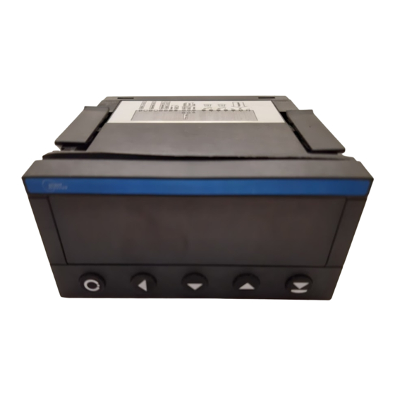
Page 4: Instrument Description
INSTRUMENT DESCRIPTION The OM 652UC model is a universal 6 digit panel programmable impulse counter/frequencymeter and stopwatch/timer. The instrument is based on an 8-bit microprocessor, which secures high accuracy, stability and easy operation of the instrument. Measuring modes COUNTER Single-channel counter... - Page 5 Time backup by means of RTC circuit is designed for the „TIMER“ measuring mode and secures time measuring even if the instrument is switched-off (without display projection). INSTRUCTIONS FOR USE OM 652UC...
-
Page 6: Instrument Connection
GND + Resetting (< 300 V) Function Description Control Hold Blocking display and instrument outputs upon contact, bracket (no. 11/12) Lock Control keys blocking upon contact, bracket (no. 11/12) Tare Tare activation upon contact, bracket (no. 11/12) INSTRUCTIONS FOR USE OM 652UC... - Page 7 Input A 170 V 13,6 V 117,8 V Resetting 211 V 17,8 V 156,0 V (< 300 V) 253 V 22,3 V 195,8 V 295 V 26,5 V 234,1 V 301 V 30,9 V 273,9 V INSTRUCTIONS FOR USE OM 652UC...
-
Page 8: Instrument Setting
• Linear menu structure • For user operation • Menu items are set by the user (Profi/Light) as per request • Access is not password protected • Optional menu structure either tree (PROFI) or linear (LIGHT) INSTRUCTIONS FOR USE OM 652UC... - Page 9 The operation program is freely accessible (www.orbit.merret.cz) and the only requirement is the purchase of OML cable to con- nect the instrument to PC. It is manufactured in version RS 232 and USB and is compatible with all ORBIT MERRET instruments.
-
Page 10: Symbols Used In The Instructions
THE MINUS SIGN Setting the minus sign is performed by the key on higher decade. When editing the item substraction must be made from the current number (e.g..: 013 > , on class 100 > -87) INSTRUCTIONS FOR USE OM 652UC... -
Page 11: Control Keys Functions
- current setting is displayed return to item item will not be displayed in USER menu item will be displayed in USER menu with the option of setting item will be solely displayed in USER menu INSTRUCTIONS FOR USE OM 652UC... -
Page 12: Setting "Light" Menu
• Only items necessary for instrument setting • Password protected access • Possibility to arrange items of the „User“ menu • Linear menu structure Preset from manufacture Password “0” Menu LIGHT USR menu Setting the items INSTRUCTIONS FOR USE OM 652UC... - Page 13 N. PASS. Identifi cation Return to previous measuring mode OM 652..142. 8 IDENT. Upon delay exceeding 60 s the programming mode is automatically discontinued and the instrument itself restores the measuring mode INSTRUCTIONS FOR USE OM 652UC...
-
Page 14: Access To Menu
- if you need to set initial value for another mode it is necessary to do so upon next access to programming menu > after Set “SET V.” = 233 Example MODE The item „SET V.“ is not projected for measuring mode „FREQU.“ INSTRUCTIONS FOR USE OM 652UC... -
Page 15: Selection Of Instrument Measuring Mode
RUn . ST. C . controlled and reset by the edge of the priming signal = COntAC. - time is set off by the edge (by the signal Selection of stopwatch control > EdGE Example CONTAC. EDGE M. STOP INSTRUCTIONS FOR USE OM 652UC... -
Page 16: Selection Of Control Stoph
The set parameter gives maximum possible frequency, which the instrument processes w/o limitation Maximum input frequency 100 Hz > 100 Example 1000 TYPE A. When accessing upon contact and available maximum input frequency we recommend using filter INSTRUCTIONS FOR USE OM 652UC... -
Page 17: Selection Of Type Of Input A
- setting level (only for type PNP) of the - table of comparing levels is on page 7 input voltage, the instrument subsequently automatically selects divider and thus the comparing levels Setting the level = 34 V Example TYPE C. INSTRUCTIONS FOR USE OM 652UC... -
Page 18: Selection Of Type Of Input C (Resetting)
- range of setting 43…300 V (Input < 300 V) input voltage, the instrument subsequently - table of comparing levels is on page 7 automatically selects divider and thus the comparing levels Setting levels = 34 V Example SCALE INSTRUCTIONS FOR USE OM 652UC... -
Page 19: Setting Multiplying Constant
312. 31. 2 DIVID. Setting division constant DIVID. Setting division constant DIVID. - calibration constant is for calculation of the input value to required display value - range: -0,00001...999999 Division constant = 22 Example OFFSET INSTRUCTIONS FOR USE OM 652UC... -
Page 20: Setting Offset - Preset
= HH.MM.SS form „FLOA. P.“ Projection of DP on display > 00000.o Example * subsequent menu item depends on instrument equipment 000000 00000. o LIM. L. 1 INSTRUCTIONS FOR USE OM 652UC... - Page 21 SETTING INSTRUCTIONS FOR USE OM 652UC...
-
Page 22: Setting Limits
* following item of the menu depends on instrument equipment, provided it has an analog MENU output the following item is „Type“ Items for “Limits” and “Analog output” are acces- sible only if the instrument contains them. INSTRUCTIONS FOR USE OM 652UC... -
Page 23: Setting Analog Output
MAX. A. O . value to the end of the = 100 AO range - range of the setting is -99999…999999 Display value for the end of the AO range > MAX. A.O. = 120 Příklad MENU INSTRUCTIONS FOR USE OM 652UC... -
Page 24: Setting The Menu Type Light/Profi
Restoration of manufacture setting > FIRM. Example FIRM. . n . P ASS. Do not perform restoration of user setting (USER) prior to its saving in Profi menu INSTRUCTIONS FOR USE OM 652UC... -
Page 25: Setting New Access Password
- the display shows the type identification of menu automatically quits the display and the instrument, SW number, SW version and measuring mode is restored current input setting (Mode) Return to measuring mode 142. 8 INSTRUCTIONS FOR USE OM 652UC... -
Page 26: Setting "Profi" Menu
• access into LIGHT menu and transition to item „MENU“ with subsequent selection of „PROFI“ and confirmation • after re-entering the menu the PROFI type is active • access is password protected (if it was not set under item N. PASS. =0) INSTRUCTIONS FOR USE OM 652UC... - Page 27 SETTING INSTRUCTIONS FOR USE OM 652UC...
-
Page 28: Resetting Internal Values
Setting the ENTER key KEYS function 6.1.1 Resetting internal values Resetting internal values CLEAR INPUT CLEAR CL. CNT. Counter resetting CL. CNT. CHANNE. CONFIG CL. TAR. Tare resetting CL. TAR. OUTPUT EXT. IN. SERVIC. KEYS INSTRUCTIONS FOR USE OM 652UC... -
Page 29: Instrument Configuration
- function allows the user a one-time setting of the display initial value CHANNE. CONFIG MODE OUTPUT EXT. IN. M. TIME SERVIC. KEYS M. S TART M. S TOP FILTER TYPE A LEVEL. A TYPE C LEVEL. C POLAR. BACKUP INSTRUCTIONS FOR USE OM 652UC... - Page 30 - in the „RTC“ regime with data projection FILTER the set time defines the cycle of switching between time/date, min. is 5 s, datue is TYPE A displayed for approx. 2,5 s LEVEL. A TYPE C LEVEL. C POLAR. BACKUP INSTRUCTIONS FOR USE OM 652UC...
- Page 31 Stopwatch/timer is CL. R U. R E. reset and set off by the edge of the priming signal, the cycle is repeated with every other edge Stopwatch/timer is only set off by the edge INSTRUCTIONS FOR USE OM 652UC...
- Page 32 LEVEL. A TYPE C. NPN. C ON. LEVEL. C POLAR. Lo \ HI / BACKUP YES NO BACKUP NO VALUE TIME EXT. IN. EXT. 1 OFF LOCK. K. HOLD TARE CLEAR CLR. ST. KEYS NO YES INSTRUCTIONS FOR USE OM 652UC...
- Page 33 HYS. L. 1 SAVE TIM. L. 1 N. PASS. LIM. 2. MOD. L. 2 HYSTER. ON RUN IDENT. OM 652UC..S. C TYP. L. 2 CLOSE OPEn LIM. L. 2 HYS. L. 2 TIM. L. 2 DATA...
- Page 34 SERVIC. M. S TART KEYS M. STOP FILTER When accessing upon contact and available TYPE A maximum input frequency we recommend using filter LEVEL. A TYPE C LEVEL. C POLAR. BACKUP INSTRUCTIONS FOR USE OM 652UC...
- Page 35 - table of comparing levels is on page 7 LEVEL. A TYPE C LEVEL. C Setting for input Resetting (Level. C) is identical with setting for Input A POLAR. Nastavení pro vstup Nulovani (Level. C) je shodné s BACKUP nastavením Vstupu A INSTRUCTIONS FOR USE OM 652UC...
- Page 36 M. TIME EXT. I N. After switch-on the instrument loads the SERVIC. KEYS FILTER display status from the memory Instrument resets itself TYPE A after switch-on LEVEL. A TYPE C LEVEL. C POLAR. BACKUP INSTRUCTIONS FOR USE OM 652UC...
-
Page 37: Setting External Control Input
Auxiliary input governs CLEAR the „Clear“ function - stopwatch/counter is cleared (preset) through the input Auxiliary input governs CLR. St. the „Clear“ function - stopwatch/counter is cleared (preset) through the input, Stopwatcg stops altogether INSTRUCTIONS FOR USE OM 652UC... -
Page 38: Setting Function Of The Control Key
Accessory functions SERVIC. KEYS are on Counter Frequency Stopwatch Resetting tare Resetting Resetting tare Display hold Tare projection Start Resetting Tare Stop Accessory functions Control keys functions are described on page 11 are off INSTRUCTIONS FOR USE OM 652UC... - Page 39 SETTING INSTRUCTIONS FOR USE OM 652UC...
-
Page 40: Profi" Menu - Channels Setting Calibration Constants And Offset
Setting division constant Setting division constant DIVID INPUT CHAN. A SET. A SCALE - division constant serves for calculation of input value to required display value CHANNE. FILTER DIVID. - range: 0,00001...999999 OUTPUT. FORM. A OFFSET SERVIC. INSTRUCTIONS FOR USE OM 652UC... -
Page 41: Setting Digital Filter
- calculation of value from the number of measurements selected in „CONST“ Selection of value ROUND. round-up - it is set by …arbitrary number, which determines the projection step (e.g.: “Con. F.A.”=2,5 > display 0, 2.5, 5,...) INSTRUCTIONS FOR USE OM 652UC... -
Page 42: Projection Format
> H.MM.SS.C HHHH. M M in hundredths of seconds > MM.SS.CC, 99.SS.CC MMMM. S S MM. S S. C C 99. S S. C C H. M M. S S. C INSTRUCTIONS FOR USE OM 652UC... - Page 43 SETTING INSTRUCTIONS FOR USE OM 652UC...
-
Page 44: Profi" Menu - Outputs Configuration And Setting The Limits
ON RUN Relay is switched on/ ON RUN OUTPUT AN. OUT. LIM. L. 2 off if the stopwatch is running SERVIC. DISP. HYS. L. 2 TIM. L. 2 Setting is available only for LIM 2 INSTRUCTIONS FOR USE OM 652UC... - Page 45 TIM. L. 1 - within the full display range Setting the offset of the TIM. L. 1 relay switch-on - within the range 0…99,9 s Setting is identical for LIM 1 and LIM 2 INSTRUCTIONS FOR USE OM 652UC...
-
Page 46: Setting Data Output
Rate - 230 400 Baud 230400 6.3.2b Setting the instrument address Setting the instrument ADDR. address INPUT LIMITS BAUD - setting within the range 0…31 = 00 CHANNE. DATA ADDR. OUTPUT. AN. OUT. SERVIC. DISP. INSTRUCTIONS FOR USE OM 652UC... -
Page 47: Setting Analog Output
- range of the setting is -99999…999999 Assigning the displayed MAX. A. O . value to the end of the analog output range - range of the setting is -99999…999999 = 100 INSTRUCTIONS FOR USE OM 652UC... -
Page 48: Setting Display Brightness
OUTPUT AN. OUT. Display brightness - 25 % SERVIC. DISP. Display brightness - 50 % Display brightness - 75 % Display brightness - 100 % 100% INSTRUCTIONS FOR USE OM 652UC... - Page 49 SETTING INSTRUCTIONS FOR USE OM 652UC...
-
Page 50: Selection Of The Type Of Programming Menu
- linear menu structure > items in succession Active PROFI menu PROFI - complete programming menu for expert Change of setting is valid with next access into menu users - tree menu INSTRUCTIONS FOR USE OM 652UC... -
Page 51: Restoration Of Manufacture Setting
SW number, SW version CHANNE. RESTOR. and current input setting (Mode) - if the SW version reads a letter on the first OUTPUT N. PASS. position, then it is a customer SW SERVIC. IDENT. INSTRUCTIONS FOR USE OM 652UC... -
Page 52: Setting "User" Menu 7.0 Configuration "User" Menu
- current setting is displayed return to item item will not be displayed in USER menu item will be displayed in USER menu with the chance of editing item will be solely displayed in USER menu INSTRUCTIONS FOR USE OM 652UC... - Page 53 CL. Cnt. LIM. L 1 0 (sequence not determined) LIM. L 2 Upon entering USER menu (key ) items will be projected in the following sequence: LIM. L 2 > CL. Cnt. > LIM. L 1 INSTRUCTIONS FOR USE OM 652UC...
-
Page 54: Data Protocol
Data - usually signs “0“…“9“, “-“, “.“; (D) - DP and (-) may prolong data …57 Relay and Tare status Positive command corfi rmation (ok) Negative command corfi rmation (bad) > Beginning of the transmitted data INSTRUCTIONS FOR USE OM 652UC... - Page 55 DATA PROTOCOL INSTRUCTIONS FOR USE OM 652UC...
-
Page 56: Error Statements
E. . DATA repeated error statement send instrument for repair Memory was empty upon repeated error statement send instrument E. CLR (presetting carried out) for repair, possible failure in calibration INSTRUCTIONS FOR USE OM 652UC... - Page 57 INSTRUCTIONS FOR USE OM 652UC...
-
Page 58: Technical Data
Input/output > 300 V (PI), 150 (DI) Relay: 1/8 HP 277 VAC, 1/10 HP 125 V, Pilot Duty D300 EMC: EN 61000-3-2+A12; EN 61000-4-2, 3, 4, 5, 8, 11; EN 550222, A1, A2 * values apply for resistance load INSTRUCTIONS FOR USE OM 652UC... - Page 59 TECHNICAL DATA INSTRUCTIONS FOR USE OM 652UC...
-
Page 60: Instrument Dimension And Installation
3. press the travellers close to the panel Instrument disassembly 1. slide a screw driver under the traveller wing 2. turn the screw driver and remove the traveller 3. take the instrument out of the panel INSTRUCTIONS FOR USE OM 652UC... -
Page 61: Certificate Of Guarantee
- unavoidable event - unavoid - other unprofessional interventions - other unprofess The manufacturer performs guarantee and post.guarantee repairs unless provided for otherwise. arantee and post.guarantee r otherwise. Y E A R S Stamp, signature INSTRUCTIONS FOR USE OM 652UC... - Page 62 NOTE INSTRUCTIONS FOR USE OM 652UC...
- Page 63 NOTE INSTRUCTIONS FOR USE OM 652UC...
-
Page 64: Declaration Of Conformity
ORBIT MERRET, spol.s r.o. and that our company has taken all measures to ensure conformity of all products of the type listed hereunder, which are being brought out to the market, with technical documentation and requirements of the appurtenant statutory orders.
Need help?
Do you have a question about the OM 652UC and is the answer not in the manual?
Questions and answers