Table of Contents
Advertisement
Quick Links
Advertisement
Chapters
Table of Contents

Related Manuals for Swan Analytical Instruments AMU Inducon


Summary of Contents for Swan Analytical Instruments AMU Inducon
- Page 1 AMU Inducon Version 6.20 and higher A-96.250.421 / 230320...
- Page 2 For any technical question, contact your nearest SWAN representative, or the manufacturer: SWAN ANALYTISCHE INSTRUMENTE AG Studbachstrasse 13 8340 Hinwil Switzerland Internet: www.swan.ch E-mail: support@swan.ch Document Status AMU Inducon Operator’s Manual Title: A-96.250.421 Revision Issue May 2008 First Edition July 2019 Update to firmware V6.20 ©...
-
Page 3: Table Of Contents
Single Components ........2.2.1 AMU Inducon Transmitter ......2.2.2 Swansensor Inducon1000. - Page 4 AMU Inducon Maintenance ........
-
Page 5: Safety Instructions
AMU Inducon Safety Instructions AMU Inducon - Operator’s Manual This document describes the main steps for instrument setup, oper- ation and maintenance. Safety Instructions General The instructions included in this section explain the potential risks associated with instrument operation and provide important safety practices designed to minimize these risks. -
Page 6: Warning Notices
AMU Inducon Safety Instructions 1.1. Warning Notices The symbols used for safety-related notices have the following sig- nificance: DANGER Your life or physical wellbeing are in serious danger if such warnings are ignored. Follow the prevention instructions carefully. WARNING Severe injuries or damage to the equipment can occur if such warnings are ignored. - Page 7 AMU Inducon Safety Instructions Warning Signs The importance of the warning signs in this manual. Electrical shock hazard Corrosive Harmful to health Flammable Warning general Attention general A-96.250.421 / 230320...
-
Page 8: General Safety Regulations
AMU Inducon Safety Instructions 1.2. General Safety Regulations Legal The user is responsible for proper system operation. All precau- tions must be followed to ensure safe operation of the instrument. Requirements Spare Parts Use only official SWAN spare parts and disposables. If other parts are used during the normal warranty period, the manufacturer’s... -
Page 9: Product Description
Application The conductivity is a parameter for the total quantity of ions present in the solution. range The AMU Inducon transmitter together with the sensor Indu- con1000 is used for applications in: chemical food & dairy refinery ... - Page 10 AMU Inducon Product Description Signal Two signal outputs programmable for measured values (freely scal- able, linear, bilinear, log) or as continuous control output (control Outputs parameters programmable). Current loop: 0/4–20 mA Maximal burden: 510 Ohm Relays Two potential-free contacts programmable as limit switches for measuring values, controllers or timer for system cleaning with au- tomatic hold function.
-
Page 11: Single Components
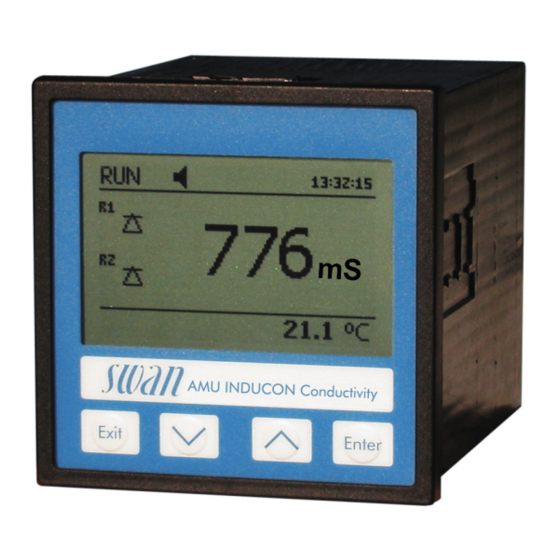
AMU Inducon Product Description 2.2. Single Components 2.2.1 AMU Inducon Transmitter ® General Electronics housing: Noryl resin Protection degree: IP54 (front) Ambient temperature: -10 to +50 °C Humidity: 10–90% rel., non condensing Display: backlit LCD, 75 x 45 mm Dimensions:... -
Page 12: Swansensor Inducon1000
AMU Inducon Product Description 2.2.2 Swansensor Inducon1000 The Swansensor Inducon1000 is used for conductivity measure- ments and monitoring of chemical concentrations and salinity. It has a toroidal design with an integrated temperature sensor. Applications chemical food & dairy ... - Page 13 AMU Inducon Product Description Sanitary Style Materials PFA Teflon® (Perfluoroalkoxy Teflon®) for (CIP) Sensor all wetted parts. Process connections Sanitary mounting, diameter 2”, with stainless steel cap Temp. & pressure limit 150 °C at 13.8 bar 39.6 mm (1.56 inches) 5/8-11 UNC 50.8 mm (2.06 inches)
-
Page 14: Installation
AMU Inducon Installation Installation 3.1. Installation Checklist Check Instrument’s specification must conform to the National Electri- cal Code, all state and local codes, and all plant codes and stan- dards for electrical equipment. Installation The transmitter is intended for panel mounting. The dimensions are shown under Dimensions of the AMU Transmitter, p. -
Page 15: Dimensions Of The Amu Transmitter
AMU Inducon Installation 3.2. Dimensions of the AMU Transmitter A-96.250.421 / 230320... -
Page 16: Electrical Connections
AMU Inducon Installation 3.3. Electrical Connections CAUTION Use only the terminals shown in this diagram, and only for the mentioned purpose. Use of any other terminals will cause short circuits with possible corresponding consequences to material and personnel. A-96.250.421 / 230320... - Page 17 AMU Inducon Installation Rear view of AMU Transmitter (+) (-) 2 3 4 5 6 7 8 9 10 11 12 13 14 RS232 RON OFF A/PB B/PB A-96.250.421 / 230320...
-
Page 18: Power Supply
60245; flammability rating FV1 Mains equipped with an external switch or circuit-breaker – near the instrument – easily accessible to the operator – marked as interrupter for AMU Inducon 3.5. Sensor Connect the sensor to the AMU transmitter according to the con- nection diagram, see Electrical Connections, p. -
Page 19: Relay Contacts
AMU Inducon Installation 3.8. Relay Contacts 3.8.1 Alarm Relay NOTICE: Max. load 100 mA/50 V Alarm output for system errors. Error codes see Error List, p. Terminals Description Active (opened) during normal operation. Normally Closed Inactive (closed) on error and loss of power. -
Page 20: 3.10. Interfaces
AMU Inducon Installation 3.10. Interfaces 3.10.1 RS232 Interface The RS232 interface is located on the back of the AMU transmitter. The RS232 interface is used for logger download and firmware up- load. 3.10.2 Profibus (optional) To connect several instruments by means of a network or to config- ure a PROFIBUS DP connection, consult the PROFIBUS manual. -
Page 21: Modbus (Optional)
AMU Inducon Installation 3.10.3 Modbus (optional) To connect several instruments by means of a network consult the MODBUS manual. Use appropriate network cable. NOTICE: The switch must be ON if only one instrument is installed, or on the last instrument in the bus. -
Page 22: Instrument Setup
AMU Inducon Instrument Setup Instrument Setup 4.1. Programming After the AMU Transmitter has been installed and all components are connected to the transmitter, switch on power. Navigate to menu <Installation>/<Sensors> and program the following parame- ters: Menu 5.1.1: Sensor parameters –... -
Page 23: Operation
AMU Inducon Operation Operation 5.1. Keys Exit Enter to exit a menu or command (rejecting any changes) to move back to the previous menu level to move DOWN in a menu list and to decrease digits to move UP in a menu list and to increase digits... -
Page 24: Display
AMU Inducon Operation 5.2. Display 15:20:18 0.15 23 l/h 23 °C normal operation HOLD input closed or cal delay: Instrument on hold (shows status of signal outputs). input closed: control/limit is interrupted (shows status of signal outputs). ERROR Error Fatal Error... -
Page 25: Software Structure
AMU Inducon Operation 5.3. Software Structure Main Menu Messages Diagnostics Maintenance Operation Installation Menu Messages 1 Messages Reveals pending errors as well as an event history Pending Errors (time and state of events that have occurred at an Message List earlier point of time). -
Page 26: Changing Parameters And Values
AMU Inducon Operation 5.4. Changing Parameters and values Changing The following example shows how to change the logger interval: parameters 1 Select the parameter you want to Sensors Logger 5.1.2 4.4.1 change. Sensor type FOME Log interval 30 min 2 Press [Enter] Disinf. -
Page 27: Maintenance
AMU Inducon Maintenance Maintenance This section describes the activities intended to retain the instru- ment in, or to restore it to a state in which it maintains the required or specified performance. 6.1. Maintenance Table If required Clean the sensor. -
Page 28: Calibration
AMU Inducon Maintenance 6.4. Calibration How often a calibration is necessary depends on your application. Usually, a calibration must be done if the cell factor is not known, the sensor has been contaminated or the maintenance measure- ment shows a discrepancy. - Page 29 AMU Inducon Maintenance Standard 1 Navigate to menu <Maintenance>/ Calibration 3.1.2 Calibration <Calibration>/<Standard>. Zero (in air) 2 Press [Enter]. Standard Process 3 Follow the instructions on the dis- play. 4 Clean the sensor according to Standard chapter Clean the Sensor, p.
-
Page 30: Longer Stop Of Operation
AMU Inducon Maintenance 6.5. Longer Stop of Operation 1 Stop sample flow. 2 Shut off power of the instrument. A-96.250.421 / 230320... -
Page 31: Error List
AMU Inducon Error List Error List Error Non-fatal Error. Indicates an alarm if a programmed value is ex- ceeded. Such Errors are marked E0xx (bold and black). Fatal Error (blinking symbol) Control of dosing devices is interrupted. The indicated measured values are possibly incorrect. - Page 32 AMU Inducon Error List Error Description Corrective action – check process E001 Conductivity Alarm high – check programmed value, see 5.3.1.1.1, p. 46 – check process E002 Conductivity Alarm low – check programmed value, see 5.3.1.1.25, p. 46 – check process...
- Page 33 AMU Inducon Error List Error Description Corrective action – check case/environment temperature E014 Case Temp. low – check programmed value, see 5.3.1.4.2, p. 47 – check control device or programming in E017 Control Timeout Installation, Relay contact, Relay 1 and 2 see 5.3.2 and 5.3.3, p.
-
Page 34: Program Overview
AMU Inducon Program Overview Program Overview For explanations about each parameter of the menus see Program List and Explanations, p. Menu 1 Messages informs about pending errors and mainte- nance tasks and shows the error history. Password protection possible. No settings can be modified. -
Page 35: Diagnostics (Main Menu 2)
AMU Inducon Program Overview 8.2. Diagnostics (Main Menu 2) Identification Desig. AMU Inducon * Menu numbers 2.1* Version V6.20-09/16 Factory Test 2.1.3.1* Instrument 2.1.3* Motherboard Front End Operating Time 2.1.4.1* Years / Days / Hours / Minutes / Seconds 2.1.4* Sensors Cond. -
Page 36: Maintenance (Main Menu 3)
AMU Inducon Program Overview 8.3. Maintenance (Main Menu 3) Calibration Zero (in air) 3.1.1.5* * Menu numbers Zero (in air) 3.1* 3.1.1* Standard 3.1.2.5* Standard 3.1.2* Process Process 3.1.3.4* 3.1.3* Simulation 3.2.1* Alarm Relay 3.2* 3.2.2* Relay 1 3.2.3* Relay 2 Signal Output 1 3.2.4*... -
Page 37: Installation (Main Menu 5)
AMU Inducon Program Overview 8.5. Installation (Main Menu 5) Sensors Sensor Parameters 5.1.1.1* * Menu numbers Cell Factor 5.1* 5.1.1* 5.1.1.2* Temp. Corr. 5.1.1.3* Standard Solution Meas. Unit 5.1.1.4* Temp. Compensation Comp. 5.1.2.1* 5.1.2* 5.1.3* Flow 5.1.4* Conc. Signal Outputs Signal Output 1 and 2 Parameter 5.2.1.1 - 5.2.2.1*... - Page 38 AMU Inducon Program Overview Input Active 5.3.4.1* * Menu numbers 5.3.4* 5.3.4.2* Signal Outputs 5.3.4.3* Output/Control 5.3.4.4* Fault 5.3.4.5* Delay Miscellaneous Language 5.4.1* 5.4* 5.4.2* Set defaults 5.4.3* Load Firmware Password 5.4.4.1* Messages 5.4.4* 5.4.4.2* Maintenance Operation 5.4.4.3* Installation 5.4.4.4* 5.4.5*...
-
Page 39: Program List And Explanations
AMU Inducon Program List and Explanations Program List and Explanations 1 Messages 1.1 Pending Errors 1.1.5 Provides the list of active errors with their status (active, acknowl- edged). If an active error is acknowledged, the alarm relay is active again. Cleared errors are moved to the Message list. -
Page 40: Maintenance
AMU Inducon Program List and Explanations 2.2.2 Miscellaneous: 2.2.2.1 Case Temp: Shows the actual temperature in °C inside the trans- mitter. 2.3 Sample 2.3.1 Sample ID: Temperature: Shows the actual temperature in °C (Pt1000) raw value in Ohm Sample flow: Shows the actual sample flow in l /h (Raw value) in Hz 2.4 I/O State... -
Page 41: Operation
AMU Inducon Program List and Explanations Press the [Enter] key. Change the value or state of the selected item with the [ ] or ] key. The value is simulated by the relay/signal output. 3.3.1 Active or inactive Alarm Relay: 3.3.2... -
Page 42: Installation
AMU Inducon Program List and Explanations 4.4.1 Log Interval: Select a convenient log interval. Consult the table be- low to estimate the max logging time. When the logging buffer is full, the oldest data record is erased to make room for the newest one (circular buffer). -
Page 43: Flow
AMU Inducon Program List and Explanations 5.1.2 Temp. Compensation: 5.1.2.1 Comp.: Choose the compensation model which fits best to your ap- plication. Available compensation models: Comp. None coefficient non-linear DIN None: No compensation should be set if you want to measure the conductivity at a certain temperature. -
Page 44: Signal Output
AMU Inducon Program List and Explanations 5.2 Signal Outputs NOTICE: The navigation in the menu <Signal Output 1> and <Signal Output 2> is identical. For reason of simplicity only the menu numbers of Signal Output 1 are used in the following. - Page 45 AMU Inducon Program List and Explanations [mA] 0 / 4 1’000 10’000 X Measured value (logarithmic) 5.2.1.40 Scaling: Enter beginning and end point (Range low & high) of the linear or logarithmic scale. In addition, the midpoint for the bilinear scale.
- Page 46 AMU Inducon Program List and Explanations As control Signal outputs can be used for driving control units. We distinguish different kinds of controls: output P-controller: The controller action is proportional to the devia- tion from the setpoint. The controller is characterized by the P-Band.
- Page 47 AMU Inducon Program List and Explanations 5.2.1.43 Control Parameters Setpoint: User-defined process value (Measured value or flow) P-Band: Range below (upwards control) or above (downwards con- trol) the setpoint, within the dosing intensity is reduced from 100% to 0% to reach the setpoint without overshooting.
- Page 48 AMU Inducon Program List and Explanations 5.3 Relay Contacts 5.3.1 Alarm Relay: The alarm relay is used as cumulative error indicator. Under normal operating conditions the contact is active. The contact is inactive at: Power loss Detection of system faults like defective sensors or electronic parts ...
- Page 49 AMU Inducon Program List and Explanations 5.3.1.2.1 Flow Alarm: Program if the alarm relay should be activated if there is a flow alarm. Choose between yes or no. The flow alarm will al- ways be indicated in the display, pending error list, saved in the message list and the logger.
- Page 50 AMU Inducon Program List and Explanations 5.3.1.5.35 Hysteresis: Within the hyst. range, the relay does not switch. This prevents damage of relays contacts when the measured value fluc- tuates around the alarm value. Range: 0–100% 5.3.1.5.45 Delay: Duration, the activation of the alarm relay is retarded after the measuring value has risen above/fallen below the programmed alarm.
- Page 51 AMU Inducon Program List and Explanations 5.3.2.400 Hysteresis: within the hysteresis range, the relay does not switch. This prevents damage of relay contacts when the measured value fluctuates around the alarm value. Parameter Range: Conductivity 0–2000 mS Temperature 0–100 °C Sample flow 0.0 –50 l/h...
- Page 52 AMU Inducon Program List and Explanations 5.3.2.32.4 Control Parameters Range for each Parameter same as 5.2.1.43, p. 45 5.3.2.32.1 Actuator = Frequency Examples of metering devices that are pulse frequency driven are the classic membrane pumps with a potential free triggering input.
- Page 53 AMU Inducon Program List and Explanations 5.3.2.6 Signal Outputs: Select operating mode of the signal output: Cont.: Signal outputs continue to issue the measured value. Signal outputs hold the last valid measured value. Hold: Measurement is interrupted. Errors, except fatal errors, are not issued.
- Page 54 AMU Inducon Program List and Explanations 5.3.2.342.2 Monday: Possible settings, on or off 5.3.2.342.8 Sunday: Possible settings, on or off 5.3.2.44 Run Time: see Interval 5.3.2.54 Delay: see Interval 5.3.2.6 Signal Outputs: see Interval 5.3.2.7 Output/Control: see Interval 5.3.2.1 Function = Fieldbus: The relay will be switched via the Profibus input.
- Page 55 AMU Inducon Program List and Explanations 5.3.4.4 Fault: No message is issued in pending error list and the alarm relay does not close when input is active. Message E024 is stored in the message list. Message E024 is issued and stored in the mes- Yes: sage list.
- Page 56 AMU Inducon Program List and Explanations 5.4.4 Password: Select a password different from 0000 to prevent unau- thorized access to the following menus: 5.4.4.1 Messages 5.4.4.2 Maintenance 5.4.4.3 Operation 5.4.4.4 Installation. Each menu may be protected by a different password.
-
Page 57: Safety Data Sheets
AMU Inducon Safety Data sheets Safety Data sheets A-87.892.400 Catalogue No.: Reference Filling Solution KCl Product name: Download The current Safety Data Sheet (SDS) for the above listed Reagent is available for downloading at www.swan.ch. MSDS A-96.250.421 / 230320... -
Page 58: Default Values
AMU Inducon Default Values Default Values Operation: Sensors: Filter Time Const.:..............20 s Hold after Cal.:................. 300 s Alarm Relay ..............same as in Installation Relay 1 and 2 ..............same as in Installation Input ..............same as in Installation Logger: Logger Interval:.............. -
Page 59: Parameter
AMU Inducon Default Values Sample Temp Alarm high: ................125 °C Alarm low:................10 °C Case temp. high: ..............65 °C Case temp. low:................. 0 °C Alarm concentration Alarm high ................100% Alarm low..................0% Hysteresis:................5.0% Relay 1 and 2 Function:................limit upper Parameter:.............. - Page 60 AMU Inducon Default Values Settings: Control Parameters: Reset time: ....... 0 s Settings: Control Parameters: Derivative Time: ....... 0 s Settings: Control Parameters: Control Timeout:....0 min Settings: Actuator:..........Time proportional Cycle time: ................60 s Response time: ..............10 s Settings: Actuator............
-
Page 61: Index
AMU Inducon Index Index ..Alarm Relay Longer Stop of Operation ..Application ..Measuring Principle ... -
Page 62: Notes
AMU Inducon Notes Notes A-96.250.421 / 230320... - Page 63 AMU Inducon Notes A-96.250.421 / 230320...
- Page 64 AMU Inducon SWAN is represented worldwide by subsidiary companies and distributors. cooperates with independent representatives all over the world. SWAN Products Analytical Instruments for: High Purity Water Feedwater, Steam and Condensate Potable Water Pool and Sanitary Water Cooling Water Waste Water and Effluents Made in Switzerland A-96.250.421 / 230320...
Need help?
Do you have a question about the AMU Inducon and is the answer not in the manual?
Questions and answers