Table of Contents
Advertisement
Quick Links
Advertisement
Chapters
Table of Contents

Related Manuals for Swan Analytical Instruments AMU Oxytrace


Summary of Contents for Swan Analytical Instruments AMU Oxytrace
- Page 1 AMU Oxytrace Version 6.20 and higher A-96.250.541 / 230320...
- Page 2 For any technical question, contact your nearest SWAN representative, or the manufacturer: SWAN ANALYTISCHE INSTRUMENTE AG Studbachstrasse 13 8340 Hinwil Switzerland Internet: www.swan.ch E-mail: support@swan.ch Document Status AMU Oxytrace Operator’s Manual Title: A-96.250.541 Revision Issue January 2008 First Edition May 2019 Update to firmware V6.20 ©...
-
Page 3: Table Of Contents
Single Components ........2.2.1 AMU Oxytrace Transmitter ......2.2.2 Sensor OXYTRACE G . - Page 4 AMU Oxytrace Maintenance ........
-
Page 5: Safety Instructions
AMU Oxytrace Safety Instructions AMU Oxytrace–Operator’s Manual This document describes the main steps for instrument setup, oper- ation and maintenance. Safety Instructions General The instructions included in this section explain the potential risks associated with instrument operation and provide important safety practices designed to minimize these risks. -
Page 6: Warning Notices
AMU Oxytrace Safety Instructions 1.1. Warning Notices The symbols used for safety-related notices have the following sig- nificance: DANGER Your life or physical wellbeing are in serious danger if such warnings are ignored. Follow the prevention instructions carefully. WARNING Severe injuries or damage to the equipment can occur if such warnings are ignored. - Page 7 AMU Oxytrace Safety Instructions Warning Signs The importance of the warning signs in this manual. Electrical shock hazard Corrosive Harmful to health Flammable Warning general Attention general A-96.250.541 / 230320...
-
Page 8: General Safety Regulations
AMU Oxytrace Safety Instructions 1.2. General Safety Regulations Legal The user is responsible for proper system operation. All precautions must be followed to ensure safe operation Requirements of the instrument. Spare Parts Use only official SWAN spare parts and disposables. If other parts are used during the normal warranty period, the manufacturer’s... -
Page 9: Product Description
2.1. Description of the System Application The AMU Oxytrace is used to measure low levels of oxygen in high-purity water. Especially in power plant water cycles (e.g. feed- water), a very low level of oxygen is needed to prevent corrosion. - Page 10 AMU Oxytrace Product Description Relay Two potential-free contacts programmable as limit switches for measuring values, controllers or timer for system cleaning with au- tomatic hold function. Maximum load: 100 mA/ 50 V Alarm Relay One potential free contact. Summary alarm indication for program- mable alarm values and Instrument faults.
- Page 11 AMU Oxytrace Product Description Fluidics Swansensor OXYTRACE G combined with QV-flow PMMA OTG flow cell: The sample flows via sample inlet [E] through the flow regulating valve [D], where the flow rate can be adjusted. Then the sample flows into the measuring cell [C] were the oxygen concentration and temperature of the sample is measured.
-
Page 12: Single Components
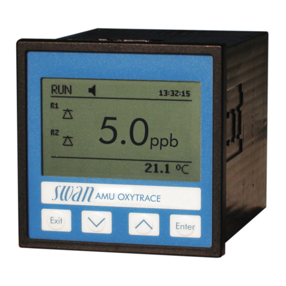
AMU Oxytrace Product Description 2.2. Single Components 2.2.1 AMU Oxytrace Transmitter ® General Electronics housing: Noryl resin Protection degree: IP54 (front) Ambient temperature: -10 to +50 °C Humidity: 10–90% rel., non condensing Display: backlit LCD, 75 x 45 mm Dimensions:... -
Page 13: Sensor Oxytrace G
AMU Oxytrace Product Description 2.2.2 Sensor OXYTRACE G Sensor for the measurement of dissolved oxygen in ultra pure wa- ter. Precise oxygen measuring cell with integrated temperature sensor and guard electrode for faster initial response time after maintenance. Technical data... -
Page 14: Qv-Flow Pmma Otg
AMU Oxytrace Product Description 2.2.3 QV-Flow PMMA OTG Flow cell Flow cell made of acrylic glass with integrated flow sensor. Sample temp. max. 50 °C Inlet pressure max. 1 bar Outlet pres- Pressure free sure Sample flow 6–25 l/h Process con- Swagelok connection for 1/4”... -
Page 15: B-Flow Ss316L Otg
AMU Oxytrace Product Description 2.2.4 B-Flow SS316L OTG Flow cell B-Flow SS316L OTG is made of stainless steel, comes without a flow sensor and can be used for higher operating pressures and temperatures. Operating -10 to +130 °C temp. Sensor max. -
Page 16: Installation
AMU Oxytrace Installation Installation 3.1. Installation Check List Instrument’s specification must conform to your power ratings. Do Check not switch on power until all external devices are connected. The transmitter is intended for panel mounting. The dimensions Installation are shown under Dimensions of the AMU Transmitter, p. -
Page 17: Dimensions Of The Amu Transmitter
AMU Oxytrace Installation 3.2. Dimensions of the AMU Transmitter A-96.250.541 / 230320... -
Page 18: Install The Swansensor Oxytrace G
AMU Oxytrace Installation Install the Swansensor Oxytrace G The Swansensor Oxytrace G is delivered with a prefilled electrolyte chamber [E]. A transport protection cap [B] filled with water [D] keeps the sensor wet during transport and storage. To install the... -
Page 19: Electrical Connection
AMU Oxytrace Installation 3.4. Electrical Connection CAUTION Use only the terminals shown in this diagram, and only for the mentioned purpose. Use of any other terminals will cause short circuits with possible corresponding consequences to material and personnel. A-96.250.541 / 230320... - Page 20 AMU Oxytrace Installation Rear view of AMU Transmitter (+) (-) 2 3 4 5 6 7 8 9 10 11 12 13 14 RS232 RON OFF A/PB B/PB A-96.250.541 / 230320...
-
Page 21: Power Supply
60245; flammability rating FV1 Mains equipped with an external switch or circuit-breaker – near the instrument – easily accessible to the operator – marked as interrupter for AMU Oxytrace 3.6. Sensor Connect the sensor Oxytrace G to the AMU transmitter according to the connection diagram, see Electrical Connection, p. -
Page 22: Relay Contacts
AMU Oxytrace Installation 3.9. Relay Contacts 3.9.1 Alarm Relay NOTICE: Max. load 100 mA/50 V Alarm output for system errors. Error codes see Error List, p. Terminals Description Active (opened) during normal operation. Normally Closed Inactive (closed) on error and loss of power. -
Page 23: Interfaces
AMU Oxytrace Installation 3.11. Interfaces 3.11.1 RS232 Interface The RS232 interface is located on the back of the AMU transmitter. The RS232 interface is used for logger download and firmware up- load. 3.11.2 Profibus (optional) To connect several instruments by means of a network or to config- ure a PROFIBUS DP connection, consult the PROFIBUS manual. -
Page 24: Modbus (Optional)
AMU Oxytrace Installation 3.11.3 Modbus (optional) To connect several instruments by means of a network consult the MODBUS manual. Use appropriate network cable. NOTICE: The switch must be ON if only one instrument is installed, or on the last instrument in the bus... -
Page 25: Instrument Setup
AMU Oxytrace Instrument Setup Instrument Setup 4.1. Establish Sample Flow 1 Open the flow regulating valve [A] and wait until the flow cell is completely filled. 2 Switch on power. 3 Adjust the sample flow to 8 –25 l/h. 4.2. -
Page 26: Operation
AMU Oxytrace Operation Operation 5.1. Keys Exit Enter to exit a menu or command (rejecting any changes) to move back to the previous menu level to move DOWN in a menu list and to decrease digits to move UP in a menu list and to increase digits... -
Page 27: Display
AMU Oxytrace Operation 5.2. Display 15:20:18 0.15 12 l/h 23 °C normal operation HOLD input closed or cal delay: Instrument on hold (shows status of signal outputs). input closed: control/limit is interrupted (shows status of signal outputs). ERROR Error Fatal Error... -
Page 28: Software Structure
AMU Oxytrace Operation 5.3. Software Structure Main Menu Messages Diagnostics Maintenance Operation Installation Menu Messages 1 Messages Reveals pending errors as well as an event history Pending Errors (time and state of events that have occurred at an Maintenance List earlier point of time). -
Page 29: Changing Parameters And Values
AMU Oxytrace Operation 5.4. Changing Parameters and values Changing The following example shows how to change the logger interval: parameters 1 Select the parameter you want to Sensors Logger 5.1.2 4.4.1 change. Sensor type FOME Log interval 30 min 2 Press [Enter] Disinf. -
Page 30: Maintenance
Maintenance Maintenance Maintenance frequency depends strongly on the water quality. The AMU Oxytrace is designed for determination of low level of dis- solved oxygen in high purity water. It is not suitable for the measurement of dissolved oxygen in waste water. -
Page 31: Maintenance Of The Oxygen Sensor
AMU Oxytrace Maintenance 6.3. Maintenance of the Oxygen Sensor WARNING Etching liquid The electrolyte is alkaline and caustic. It contains less than 1% of potassium hydroxide. Do not ingest. Wear protective goggles and gloves during handling. Avoid contact with clothes. - Page 32 AMU Oxytrace Maintenance Swansensor Oxytrace G Thread Groove Guard electrode Anode Measuring head Cathode Sensor cap with membrane 3 Unscrew and remove the sensor cap [H] from the Swansensor Oxytrace G [A]. 4 Empty the remaining electrolyte. 5 Refill the sensor cap with fresh electrolyte.
-
Page 33: Clean Swansensor Oxytrace G And Flow Cell
AMU Oxytrace Maintenance 6.3.2 Clean Swansensor Oxytrace G and Flow Cell Depending on the water quality, the Swansensor Oxytrace G and the flow cell will necessitate a cleaning. Before cleaning, stop operation as described in Stop of Operation for Maintenance, p. -
Page 34: Calibration
AMU Oxytrace Maintenance 6.4. Calibration The sensing part of the sensor must not be in direct contact with water! In the wet flow cell, the atmosphere will be saturated with water va- por. This atmosphere will produce the most accurate calibration re- sults. - Page 35 AMU Oxytrace Maintenance 7 Place the electrode slightly tilted Calibration 3.1.5 into the flow cell, so that the sensor Place the electrode into cap rests on the rim for the O-ring. the wet flow cell at a slightly tilted angle.
-
Page 36: Zero-Verification
AMU Oxytrace Maintenance 6.5. Zero-Verification Swansensor Oxytrace G for the measurement of low oxygen con- tent (<1 ppb). 1 Calibrate the sensor according to chapter Calibration, p. 2 Prepare a 5%-sodium sulfite solution with demineralized water. 3 Put the electrode into the sodium sulfite solution afterwards. As- sure that there are no air bubbles in front of the sensor. -
Page 37: Error List
AMU Oxytrace Error List Error List Error Non-fatal Error. Indicates an alarm if a programmed value is ex- ceeded. Such Errors are marked E0xx (bold and black). Fatal Error (blinking symbol) Control of dosing devices is interrupted. The indicated measured values are possibly incorrect. - Page 38 AMU Oxytrace Error List Error Description Corrective action – check process E001 Oxygen Alarm high – check programmed value, 5.3.1.1.1, S. 53 – check process E002 Oxygen Alarm low – check programmed value, 5.3.1.1.25, S. 53 – check process E003 Saturation Alarm high –...
- Page 39 AMU Oxytrace Error List Error Description Corrective action – check case/environment temperature E013 Case Temp. high – check programmed value, 5.3.1.5.1, S. 54 – check case/environment temperature E014 Case Temp. low – check programmed value, 5.3.1.5.2, S. 54 – check control device or programming in...
-
Page 40: Program Overview
AMU Oxytrace Program Overview Program Overview For explanations about each parameter of the menus see Program List and Explanations, S. Menu 1 Messages informs about pending errors and mainte- nance tasks and shows the error history. Password protection possible. No settings can be modified. -
Page 41: Diagnostics (Main Menu 2)
AMU Oxytrace Program Overview 8.2. Diagnostics (Main Menu 2) Identification Desig. AMU Oxytrace * Menu numbers 2.1* Version 6.20-06/16 Factory Test 2.1.3.1* Instrument 2.1.3* Motherboard Front End Operating Time 2.1.4.1* Years / Days / Hours / Minutes / Seconds 2.1.4*... -
Page 42: Maintenance (Main Menu 3)
AMU Oxytrace Program Overview 8.3. Maintenance (Main Menu 3) Calibration 3.1.5 * Menu numbers Calibration 3.1* Service Electrolyte Last filling 3.2* 3.2.1* Remaining amount Remaining time 3.2.1.5* New Filling Simulation 3.2.1* Alarm Relay 3.3* Relay 1 3.2.2* Relay 2 3.2.3* 3.2.4*... -
Page 43: Operation (Main Menu 4)
AMU Oxytrace Program Overview 8.4. Operation (Main Menu 4) Sensors 4.1.1* * Menu numbers Filter Time Const. 4.1* 4.1.2* Hold after Cal. Relay Contacts Alarm Relay Alarm Oxygen Alarm High 4.2.1.1.1* 4.2* 4.2.1* 4.2.1.1* 4.2.1.1.25* Alarm Low 4.2.1.1.35* Hysteresis 4.2.1.1.45*... -
Page 44: Installation (Main Menu 5)
AMU Oxytrace Program Overview 8.5. Installation (Main Menu 5) Sensors Miscellaneous 5.1.1.1* * Menu numbers Flow 5.1* 5.1.1* 5.1.1.2* Offset Quality Assurance 5.1.2.1* Level 5.1.2* Signal Outputs Signal Output 1 /2 5.2.1.1 - 5.2.2.1* Parameter 5.2* 5.2.1* - 5.2.2* 5.2.1.2 - 5.2.2.2* Current Loop 5.2.1.3 - 5.2.2.3*... - Page 45 AMU Oxytrace Program Overview Miscellaneous Language 5.4.1* * Menu numbers 5.4* 5.4.2* Set defaults 5.4.3* Load Firmware Password 5.4.4.1* Messages 5.4.4* 5.4.4.2* Maintenance Operation 5.4.4.3* 5.4.4.4* Installation 5.4.5* Sample ID Interface 5.5.1* (only with RS485 Protocol 5.5* 5.5.21* interface) Device Address Baud Rate 5.5.31*...
-
Page 46: Program List And Explanations
AMU Oxytrace Program List and Explanations Program List and Explanations 1 Messages 1.1 Pending Errors 1.1.5 Provides the list of active errors with their status (active, acknowl- edged). If an active error is acknowledged, the alarm relay is active again. Cleared errors are moved to the Message list. - Page 47 AMU Oxytrace Program List and Explanations 2.2.1.4 Cal. History Review the diagnostic values of the last calibration of the oxygen sensor. Max. 64 data records are memorized. Number: Calibration counter. Date, Time: Date and time of the calibration. Sat. Current: Saturation current at that time of calibration.
-
Page 48: Maintenance
AMU Oxytrace Program List and Explanations 3 Maintenance 3.1 Calibration 3.1.1 Start a calibration and follow the instructions on the screen. Dis- played values are saturation in % and the saturation current in µA. The indication bar shows the progress. Detailed explanation see Calibration, p. -
Page 49: Operation
AMU Oxytrace Program List and Explanations 3.4 Set Time Adjust date and time. 3.5 Quality Assurance Performs a Quality Assurance according to your settings. Follow the commands on the screen. 4 Operation 4.1 Sensors 4.1.1 Filter Time Constant: Used to damp noisy signals. The higher the filter time constant, the slower the system reacts to changes of the measured value. -
Page 50: Installation
AMU Oxytrace Program List and Explanations 5 Installation 5.1 Sensors 5.1.1 Miscellaneous 5.1.1.1 Flow: If a flow cell without flow measurement (e.g. B-Flow) is used, choose none. With flow measurement select Q-Flow 5.1.1.2 O2 Offset: Manual, small correction of the offset. - Page 51 AMU Oxytrace Program List and Explanations 5.2.1.3 Function: Define if the signal output is used to transmit a process value or to drive a control unit. Available functions are: Linear, bilinear or logarithmic for process values. As process values, p. 49 ...
- Page 52 AMU Oxytrace Program List and Explanations Parameter: Oxygen Range low: 0.00 ppb –20.00 ppm Range high: 0.00 ppb –20.00 ppm Parameter: Temperature Range low: -30 to + 130 °C Range high: -30 to + 130 °C Parameter: Sample flow Range low: 0–50 l/h Range high: 0–50 l/h...
- Page 53 AMU Oxytrace Program List and Explanations Ziegler-Nichols method for the optimization of a PID controller: Parameters: Setpoint, P-Band, Reset time, Derivative time Response to maximum control output = 1.2/a Tangent on the inflection point = 2L Time = L/2 The point of intersection of the tangent with the respective axis will result in the parameters a and L.
- Page 54 AMU Oxytrace Program List and Explanations 5.2.1.43 Control Parameters: if Parameter = Sample flow 5.2.1.43.12 Setopint: Range: 0–50 l/h 5.2.1.43.22 P-Band: Range: 0–50 l/h 5.2.1.43 Control Parameters: if Parameter = Saturation 5.2.1.43.13 Setopint: Range: 0–200% 5.2.1.43.23 P-Band: Range: 0–200% 5.2.1.43.3...
- Page 55 AMU Oxytrace Program List and Explanations 5.3.1.1 Alarm oxygen 5.3.1.1.1 Alarm High: If the measured value rises above the alarm high value, the alarm relay is activated and E001 is displayed in the message list. Range: 0.00 ppb –20.00 ppm 5.3.1.1.25...
- Page 56 AMU Oxytrace Program List and Explanations 5.3.1.4 Alarm Saturation 5.3.1.4.1 Alarm High: If the measured value rises above the alarm high val- ue, the alarm relay is activated and E003, is displayed in the mes- sage list. Range: 0.00 –200% 5.3.1.4.25...
- Page 57 AMU Oxytrace Program List and Explanations 5.3.2.1 Function = Limit upper/lower: When the relays are used as upper or lower limit switches, program the following: 5.3.2.20 Parameter: choose one of the following process values Oxygen Temperature Sample Flow ...
- Page 58 AMU Oxytrace Program List and Explanations 5.3.2.22 Parameter: choose one of the following process values Oxygen Temperature Sample Flow Saturation 5.3.2.32 Settings Choose the respective actuator: Time proportional Frequency Motor valve Actuator = Time proportional Examples of metering devices that are driven time proportional are solenoid valves, peristaltic pumps.
- Page 59 AMU Oxytrace Program List and Explanations 5.3.2.32.4 Control Parameters: Range for each Parameter same as 5.2.1.43, p. 51 5.3.2.1 Function = Timer The relay will be activated repetitively depending on the pro- grammed time scheme. 5.3.2.24 Mode: Operating mode (interval, daily, weekly) 5.3.2.24...
- Page 60 AMU Oxytrace Program List and Explanations 4 Set the minutes with the [ ] or [ ] keys. 5 Press [Enter], to set the seconds. 6 Set the seconds with the [ ] or [ ] keys. Range: 00:00:00–23:59:59 5.3.2.44 Run Time: see Interval 5.3.2.54...
- Page 61 AMU Oxytrace Program List and Explanations 5.3.4.2 Signal Outputs: Select the operation mode of the signal outputs when the relay is active: Cont.: Signal outputs continue to issue the measured value. Signal outputs issue the last valid measured Hold: value.
- Page 62 AMU Oxytrace Program List and Explanations 5.4.3 Load Firmware: Firmware updates should be done by instructed service personnel only. 5.4.4 Password: Select a password different from 0000 to prevent unau- thorized access to the menus “Messages”, “Maintenance”, “Opera- tion” and “Installation”.
-
Page 63: Material Safety Data Sheets
AMU Oxytrace Material Safety Data sheets Material Safety Data sheets 10.1. Reagents Catalogue No.: 102751.10 Product name: Filling solution 1ALK Part of: A-87.290.060 Download The current Material Safety Data Sheets (MSDS) for the above list- ed Reagents are available for downloading at www.swan.ch. -
Page 64: Default Values
AMU Oxytrace Default Values Default Values Operation: Sensors: Filter Time Const.:..............10 s Hold after Cal.:................. 300 s Alarm Relay ..............same as in Installation Relay 1/2 ..............same as in Installation Input ..............same as in Installation Logger: Logger Interval:..............30 min Clear Logger: ................ - Page 65 AMU Oxytrace Default Values Case temp. high: ..............65 °C Case temp. low:................. 0 °C Relay 1 Function:................limit upper Parameter:................Oxygen Setpoint: ................10.00 ppm Hysteresis:................100 ppb Delay: ..................30 s Relay 2 Function:................limit upper Parameter:..............Temperature Setpoint: ................50.0 °C Hysteresis:................
- Page 66 AMU Oxytrace Default Values Miscellaneous Language:................English Set default:..................no Load firmware: ................no Password: ............for all modes 0000 Sample ID: ............... - - - - - - - - Interface Protocol:..............Hyperterminal A-96.250.541 / 230320...
-
Page 67: Index
AMU Oxytrace Index Index ..Alarm Relay Longer Stop of Operation ....B-Flow SS316L OTG Modbus ... -
Page 68: Notes
AMU Oxytrace Notes Notes A-96.250.541 / 230320... - Page 69 AMU Oxytrace Notes A-96.250.541 / 230320...
- Page 70 AMU Oxytrace SWAN is represented worldwide by subsidiary companies and distributors. cooperates with independent representatives all over the world. SWAN Products Analytical Instruments for: High Purity Water Feedwater, Steam and Condensate Potable Water Pool and Sanitary Water Cooling Water Waste Water and Effluents Made in Switzerland A-96.250.541 / 230320...
Need help?
Do you have a question about the AMU Oxytrace and is the answer not in the manual?
Questions and answers