Table of Contents
Advertisement
Advertisement
Table of Contents

Related Manuals for Swan Analytical Instruments AMI Soditrace


Summary of Contents for Swan Analytical Instruments AMI Soditrace
- Page 1 AMI Soditrace Version 6.10 and higher A-96.250.551 / 100717...
- Page 2 For any technical question, contact your nearest SWAN representative, or the manufacturer: SWAN ANALYTISCHE INSTRUMENTE AG Studbachstrasse 13 8340 Hinwil Switzerland Internet: www.swan.ch E-mail: support@swan.ch Document Status AMI Soditrace Operator’s Manual Title: A-96.250.551 Revision Issue Sept. 2009 Preliminary Edition Nov. 2009 Oct. 2012 Update to Firmware version 5.30, USB interface...
-
Page 3: Table Of Contents
AMI Soditrace Table of Contents Safety Instructions ........ - Page 4 AMI Soditrace 4.2.4 Test Valve 5........
- Page 5 AMI Soditrace Program List and Explanations......1 Messages .........
-
Page 6: Safety Instructions
AMI Soditrace Safety Instructions AMI Soditrace - Operator’s Manual This document describes the main steps for instrument setup, oper- ation and maintenance. Safety Instructions General The instructions included in this section explain the potential risks associated with instrument operation and provide important safety practices designed to minimize these risks. -
Page 7: Warning Notices
AMI Soditrace Safety Instructions 1.1. Warning Notices The symbols used for safety-related notices have the following sig- nificance: DANGER Your life or physical wellbeing are in serious danger if such warnings are ignored. Follow the prevention instructions carefully. WARNING Severe injuries or damage to the equipment can occur if such warnings are ignored. -
Page 8: General Safety Regulations
AMI Soditrace Safety Instructions Warning Signs The importance of the warning signs in this manual. Electrical shock hazard Corrosive Harmful to health Flammable Warning general Attention general 1.2. General Safety Regulations Legal The user is responsible for proper system operation. - Page 9 AMI Soditrace Safety Instructions Modifications Modifications and instrument upgrades shall only be carried out by an authorized Service Technician. SWAN will not accept responsi- bility for any claim resulting from unauthorized modification or alter- ation. WARNING Electrical Shock Hazard If proper operation is no longer possible, the instrument must be disconnected from all power lines, and measures must be taken to prevent inadvertent operation.
-
Page 10: Product Description
AMI Soditrace Product Description Product Description 2.1. Description of the System Application Sodium measurement is used for quality control in high purity water applications and to monitor break through of ion exchangers. Range Signal Two signal outputs programmable for measured values (freely scal-... - Page 11 AMI Soditrace Product Description Measuring The sodium measurement as used in this instrument is based on a proven glass ion sensitive electrode. The logarithmic response can principle be described as follows: E = E + SI * log {(C ) / C...
- Page 12 AMI Soditrace Product Description Fluidics overview Temperature sensor Calibration chamber Reference electrode Constant head Sodium electrode Conductivity sensor Standard solution Air lift pump Regeneration solution Calibration loop Air pump Flow regulating valve Reference chamber Overflow constant head Overflow low level...
- Page 13 AMI Soditrace Product Description Solenoid The following illustration gives an overview about the solenoid valve position on the valve block [C] and their switching state if they valves are de-energized. Solenoid valve de-energized Solenoid valve energized Valve block normally open...
- Page 14 AMI Soditrace Product Description On-line During on-line operation the AMI Soditrace works in the Mode <Low Level>. operation The sample enters the system at the sample inlet [P] and flows into the constant head [J]. Adjust the flow regulating valve [N] so that always a small part of the sample flows through the overflow tube [O] into the waste.
- Page 15 AMI Soditrace Product Description Temperature sensor Calibration chamber Reference electrode Constant head Sodium electrode Conductivity sensor Standard solution Air lift pump Regeneration solution Calibration loop Air pump Flow regulating valve Reference chamber Overflow constant head Low level overflow Sample inlet...
- Page 16 AMI Soditrace Product Description Temperature sensor Calibration chamber Reference electrode Constant head Sodium electrode Conductivity sensor Standard solution Air lift pump Regeneration solution Calibration loop Air pump Flow regulating valve Reference chamber Overflow constant head Overflow low level Sample inlet...
- Page 17 AMI Soditrace Product Description Temperature sensor Calibration chamber Reference electrode Constant head Sodium electrode Conductivity sensor Standard solution Air lift pump Regeneration solution Calibration loop Air pump Flow regulating valve Reference chamber Overflow constant head Overflow low level Sample inlet...
- Page 18 AMI Soditrace Product Description When the valves are deactivated, the content of the calibration loop is flushed into the measuring cell. For the first calibration point, the calibration loop is filled once with standard and then flushed into the measuring cell. The sample is then recirculated until a constant mV reading is attained.
- Page 19 AMI Soditrace Product Description For the second calibration point, the calibration loop is filled and flushed, twice. Again the sample is recirculated until a constant mV reading is attained. For the third calibration point, the calibration loop is filled and flushed, seven times.
-
Page 20: Instrument Specification
AMI Soditrace Product Description 2.2. Instrument Specification Power Supply Voltage: 100–240 VAC (± 10%) 50/60 Hz (± 5%) or 24 VDC (± 10%) Power consumption: max. 30 VA Electronics Aluminium with a protection degree of IP 66 / NEMA 4X... - Page 21 AMI Soditrace Product Description Dimensions Panel: 400x860x150 mm, stainless steel Screws: 8 mm diameter Weight: 13.0 kg /28.70 lbs 400 (15.7”) 374 (14.7”) A-96.250.551 / 100717...
-
Page 22: Instrument Overview
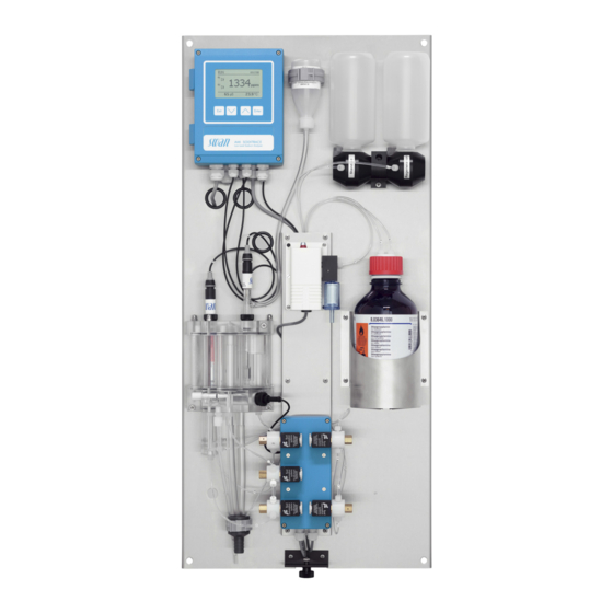
AMI Soditrace Product Description 2.3. Instrument Overview Panel Valve block Transmitter Waste Reference electrolyte bottle Sample inlet Standard solution Flow regulating valve Regeneration solution Flow cell Air pump Sodium electrode Air filter Reference electrode Reagent bottle (DIPA) Temperature sensor (behind... -
Page 23: Installation
AMI Soditrace Installation Installation 3.1. Installation Checklist Monitors Check Instrument’s specification must conform to the National Electrical Code, all state and local codes, and all plant codes and standards for electrical equipment. On site require- 100–240 VAC (± 10%), 50/60 Hz (± 5%) or 24 VDC, isolated ments (±15%) power outlet with ground connection and 20 VA... -
Page 24: Mounting Of Instrument Panel
AMI Soditrace Installation Power-up Open the flow regulating valve and adjust the sample flow. Wait until the flow cell is completely filled. Switch on power. Program all parameters for sensor and external devices Instrument (interface, recorders, etc.). set-up Program all parameters for instrument operation (limits, alarms). -
Page 25: Connecting Sample And Waste
AMI Soditrace Installation 3.3. Connecting Sample and Waste Sample inlet Use plastic tube (FEP, PA, or PE 4 x 6 mm) to connect the sample inlet and outlet. CAUTION Damage of flow cell possible Never use steel tubings or fittings directly on the acrylic glass. -
Page 26: Installation Of Electrodes
AMI Soditrace Installation 3.4. Installation of Electrodes Position of The cables of the electrodes are already connected. The tempera- ture sensor is fixed to the mounting panel with a tape. The conduc- electrodes in tivity sensor is factory-mounted. the flow cell The Picture below shows the measuring cell with the electrode’s... -
Page 27: Install The Sodium Electrode
AMI Soditrace Installation 3.4.1 Install the Sodium Electrode General Sodium electrodes are sensitive, electrochemical devices with a very high internal impedance. To maintain correct operation make sure that: the sensing glass bulb stays clean. no air bubbles are trapped in the glass bulb of the electrode. -
Page 28: Install The Reference Electrode
AMI Soditrace Installation 5 Insert the electrode into the measuring chamber [C] and push down completely. 6 Tighten the union screw [F] finger tight. 7 Remove the connector cap [B] from the electrode. 8 Screw the connector [A] onto the electrode. - Page 29 AMI Soditrace Installation Prepare the After longer storage of the reference electrode, the diaphragm may be clogged wit salt deposits of KCl. Therefore it is recommended to reference elec- open an clean the diaphragm before installing the reference elec- trode trode.
- Page 30 AMI Soditrace Installation 8 Push the ring-shaped sleeve carefully over the ground-joint dia- phragm. NOTICE: Air bubbles trapped in the dosing tip of the KCl bottle may stop the KCl flow to the reference electrode, which results in wrong measuring values.
-
Page 31: Install The Temperature Sensor
AMI Soditrace Installation 5 Remove the connector cap [B] from the electrode. 6 Screw the connector [A] onto the electrode. 3.4.3 Install the Temperature Sensor The temperature sensor is fixed to the panel with an adhesive tape and already connected to the front end PCB in the AMI transmitter. -
Page 32: Install Standard And Regeneration Bottle
AMI Soditrace Installation 3.5. Install Standard and Regeneration Bottle Exit Enter Standard bottle Regeneration bottle Bottle holder Pressure compensation Mixing Prepare sodium standard using the 1’000 ppm stock solution. The standard final concentration must correspond to the concentrations pro- grammed in the instrument (default = 16 ppm). - Page 33 AMI Soditrace Installation Meas. Range Amount of standard Result < 1 ppb 2 ml 4’000 ppb (4 ppm) < 5 ppb 5 ml 10’000 ppb < 10 ppb 10 ml 20’000 ppb NOTICE: • Do not prepare standards below 1 ppm.
-
Page 34: Install Reagent Bottle
AMI Soditrace Installation 3.6. Install Reagent Bottle WARNING Diisopropylamine is corrosive. Read the Safety Data Sheets (SDS) first. Wear suitable protective clothing, gloves and eye/face protec- tion. Avoid inhalation of DIPA vapor. To prevent formation of re- agent vapors: –... -
Page 35: Install Air Filter
AMI Soditrace Installation 1 Put the DIPA bottle [G] into the bottle holder [H] 2 Put the tube holder onto the DIPA bottle 3 Screw the screw cover onto the DIPA bottle and tighten it firmly. 3.7. Install Air Filter... -
Page 36: Electrical Connections
AMI Soditrace Installation 3.8. Electrical Connections WARNING Risk of electrical shock. Do not perform any work on electrical components if the trans- mitter is switched on. Failure to follow safety instructions could result in serious injury or death. Always turn off AC power before manipulating electric parts. - Page 37 AMI Soditrace Installation WARNING External Voltage. External supplied devices connected to relay 1 or 2 or to the alarm relay can cause electrical shocks Make sure that the devices connected to the following con- tacts are disconnected from the power before resuming in- stallation.
-
Page 38: Connection Diagram
AMI Soditrace Installation 3.8.1 Connection Diagram CAUTION Use only the terminals shown in this diagram, and only for the mentioned purpose. Use of any other terminals will cause short circuits with possible corresponding consequences to material and personnel. A-96.250.551 / 100717... -
Page 39: Power Supply
Mains cable to comply with standards IEC 60227 or IEC 60245; flammable rating FV1 Mains equipped with an external switch or circuit-breaker – near the instrument – easily accessible to the operator – marked as interrupter for AMI Soditrace A-96.250.551 / 100717... -
Page 40: Relay Contacts
AMI Soditrace Installation 3.9. Relay Contacts Programming of the relay contacts see 5.3 Relay Contacts, p. 78 3.9.1 Input NOTICE: Use only potential-free (dry) contacts. The total resistance (sum of cable resistance and resistance of the relay contact) must be less than 50 Ω. -
Page 41: Relay Contacts 1 And 2
AMI Soditrace Installation 3.9.3 Relay Contacts 1 and 2 NOTICE: Rated load 1 AT / 250 VAC Relay 1 and 2 can be configured as normally open or as normally closed. Standard for both relays is normally open. To configure a Relay as normally closed, set the jumper in the upper position. - Page 42 AMI Soditrace Installation CAUTION Risk of damage of the relays in the AMI Transmitter due to heavy inductive load. Heavy inductive or directly controlled loads (solenoid valves, dosing pumps) may destroy the relay contacts. To switch inductive loads > 0.1 A use an AMI relay box avail- able as an option or suitable external power relays.
-
Page 43: Signal Outputs
AMI Soditrace Installation 3.10. Signal Outputs 3.10.1 Signal Output 1 and 2 (current outputs) NOTICE: Max. burden 510 Ω. If signals are sent to two different receivers, use signal isolator (loop isolator). Signal output 1: Terminals 14 (+) and 13 (-) -
Page 44: Signal Output 3
AMI Soditrace Installation 3.11.1 Signal Output 3 Terminals 38 (+) and 37 (-). Requires the additional board for the third signal output 0/4–20 mA. The third signal output can be operated as a current source or as a current sink (switchable via switch [A]). For detailed information see the corresponding installation instruction. -
Page 45: Usb Interface
AMI Soditrace Installation 3.11.3 USB Interface The USB Interface is used to store Logger data and for Firmware upload. For detailed information see the corresponding installation instruction. The optional third signal output 0/4 – 20 mA PCB [B] can be plugged onto the USB interface and used in parallel. -
Page 46: Instrument Setup
AMI Soditrace Instrument Setup Instrument Setup 4.1. Establish Sample Flow 1 Open sample flow tap. 2 Wait until the flow cell is completely filled. 3 Switch on power. 4.2. Liquid System Function Test The liquid system function test is of vital importance to make sure that all tubes are filled and connected without leakage and that all solenoid valves are working properly. -
Page 47: Hi Level Test
AMI Soditrace Instrument Setup 4.2.1 Hi Level Test With the test “Hi Level” the function of valve 1 is tested. High level must be reached within 4 minutes. Low level High level If High Level is not reached within 4 minutes, see Problems During Valve Block Test, p. -
Page 48: Fill Loop
AMI Soditrace Instrument Setup 4.2.2 Fill Loop With the test “Fill Loop” the function of valve 2 and 3 activated is tested. Standard flow is ok if air bubbles are formed in the standard bottle. If no air bubbles are formed in the standard bottle see Problems During Valve Block Test, p. -
Page 49: Test Valve 5
AMI Soditrace Instrument Setup 4.2.4 Test Valve 5 Navigate to Menu <Man. Regeneration> and start the function re- generation: The instrument displays the actual state of the regeneration pro- cess in the following order: Mix –> Regenerate –> End. If Regenerate is displayed, valve 5 is opened and regeneration solution flows through tube 13, valve 5, and tube 10 into the flow cell. -
Page 50: Test Valve 4
AMI Soditrace Instrument Setup 4.2.5 Test Valve 4 Perform this test only after all other tests have been completed suc- cessfully. WARNING DIPA is Flammable Corrosive Harmful Carefully read the Safety Data Sheet before handling DIPA With this test the control of valve 4 via conductivity sensor is tested. -
Page 51: Programming
AMI Soditrace Instrument Setup 4.3. Programming 4.3.1 Calendar The implemented calendar is based on the CRON format. It starts with Sunday and ends with Saturday. Usually a month has three full weeks and two weeks which are part thereof. Therefore, if you program a task which has to be carried out weekly, always program the task in the 2nd, 3rd or 4th week of a month. - Page 52 AMI Soditrace Instrument Setup To change the settings of Monday Monday 5.1.2.2.1.1 Press <Enter> 1st weekoff 1st week is already highlighted. Navi- 2nd week gate to 3rd week. 3rd week 4th week Last week Press <Enter>. Monday 5.1.2.2.1.1 Navigate to “regenerate”.
-
Page 53: Operation
AMI Soditrace Operation Operation 5.1. Keys Exit Enter to exit a menu or command (rejecting any changes) to move back to the previous menu level to move DOWN in a menu list and to decrease digits to move UP in a menu list and to increase digits... -
Page 54: Display
AMI Soditrace Operation 5.2. Display 15:20:18 0.008 448 µS 24.8°C normal operation HOLD input closed or cal delay: Instrument on hold (shows status of signal outputs). input closed: control/limit is interrupted (shows status of signal outputs). ERROR Error Fatal Error... -
Page 55: Software Structure
AMI Soditrace Operation 5.3. Software Structure Main Menu Messages Diagnostics Maintenance Operation Installation Menu Messages 1 Messages Reveals pending errors as well as an event history Pending Errors (time and state of events that have occurred at an Maintenance List earlier point of time). -
Page 56: Changing Parameters And Values
AMI Soditrace Operation 5.4. Changing Parameters and values The following example shows how to change the Signal Output 2: Changing 1 Select the parameter you want to Signal Output 2 5.2.2.1 parameters change. Parameter Temperature 2 Press <Enter> Current Loop... -
Page 57: Maintenance
AMI Soditrace Maintenance Maintenance WARNING Stop operation before maintenance. Remove DIPA bottle and wait until conductivity is approxi- mately 0. Stop sample flow. Shut off power of the instrument. 6.1. Maintenance Schedule Weekly or Check air lift pump for regular bubble formation. -
Page 58: Maintenance Of Sodium Electrode
AMI Soditrace Maintenance 6.2. Maintenance of Sodium Electrode Sodium electrodes are sensitive electrochemical devices with very high internal impedance. To maintain correct operation, make sure that. the sensing glass bulb stays clean no air bubbles are trapped between glass bulb and glass tube ... -
Page 59: Maintenance Of Reference Electrode
AMI Soditrace Maintenance 6.3. Maintenance of Reference Electrode Sensor plug Connector cap Union screw Washer O-ring Ring-shaped sleeve Remove the 1 Completely unscrew the union screw [C] from the threaded hole. reference electrode 2 Remove the KCl bottle from its holder. -
Page 60: Maintenance Of Conductivity Sensor
AMI Soditrace Maintenance 6.4. Maintenance of Conductivity Sensor The conductivity sensor is used to maintain a constant conductivity of 450 µS/cm. To get correct measuring values, it is of vital impor- tance, that the conductivity sensor is installed and aligned correctly. -
Page 61: Maintenance Of Solenoid Valve
AMI Soditrace Maintenance 6.5. Maintenance of Solenoid Valve NOTICE: Never use the membranes again after a valve has been opened. Dismount 1 Drain the measuring cell completely before dismounting a sole- noid valve. 2 Tilt the standard and the regeneration bottle down. - Page 62 AMI Soditrace Maintenance Drawing Knurled nut Coil body Solenoid support Washer 2 Long spring Solenoid with membrane holder Membrane 2 Valve body Teflon distance bar Membrane 1 Membrane holder Conical spring Washer 1 Bottom nut Assembling 1 Put new membranes on the membrane holders.
-
Page 63: Maintenance Of Flow Cell
AMI Soditrace Maintenance 6.6. Maintenance of Flow Cell CAUTION Possible damage of acrylic glass parts due to scrubbing materials. Never use organic solvents or scrubbing materials to clean acrylic glass parts. Use soft detergent and rinse well. NOTICE: Never use silicone oil or grease to seal standard bottle holder and o-rings. - Page 64 AMI Soditrace Maintenance Exploded Union screw M20 drawing Washer O-ring 11x3.5 Screw M5x115 Cover plate O-ring 54x3.5 O-ring 34x3.5 Calibration cell tube Constant head tube Reference cell tube Measuring cell tube Overflow tube low level Overflow tube high level Overflow tube...
- Page 65 AMI Soditrace Maintenance Assembling 1 Mount the o-rings on all tubes. 2 Insert the measuring cell tube [K] into the inner bore at the left side of the base plate (see exploded drawing). 3 Insert the overflow tube low level [L] into the inner bore at the right side of the base plate (see exploded drawing).
-
Page 66: Process Calibration
AMI Soditrace Maintenance 6.7. Process Calibration The process calibration is based on a comparative measurement of the on-line instrument with a correct manual measurement with any instrument. Then compare the measuring value of the manual mea- surement with the on-line instrument and if necessary, enter the correct measuring value in the menu <Maintenance/Process Cal.>... -
Page 67: Regeneration
AMI Soditrace Maintenance 6.8. Regeneration The regeneration is used to etch the sodium sensor periodically. This guarantees a fast response and reliable measurement values over al long time and extended life time of the sodium sensor. If performing Performing a manual regeneration is only recommended after com-... -
Page 68: Calibration
AMI Soditrace Maintenance 6.9. Calibration The 3-point calibration is used to recalculate the slope and deter- mine the offset of the sodium sensor periodically. The calibration consists of three steps. On each step an exactly de- fined amount of a known concentration of a standard solution is added to the closed sample loop. -
Page 69: Verification
AMI Soditrace Maintenance End of calibration procedure: Man. Calibration 3.2.3.5 Press <Enter> to save the Offset 124.00 mV calibration Slope 59.22 mV Press <Exit> to discharge the calibration Save <Enter> The settings in <Installation/Sensors/Maintenance Plan> are also valid during the manual regeneration. This means, the signal... - Page 70 AMI Soditrace Maintenance Start of verification procedure: Man. Verification 3.2.4.5 State: Shows all verification steps State Hi Level Current value: Current value 0.030 ppb Timer 217 Sec Timer: Progress Verification time <Exit> to cancel End of verification procedure: Man.
-
Page 71: Tube Replacement
AMI Soditrace Maintenance 6.11. Tube Replacement 6.11.1 Tube Numbering Number Length from Measuring Cell Constant Head Valve 2 NC Measuring Cell Calibration Cell Valve 2 NO Measuring Cell Air lift Pump Valve 3 NO Standard Bottle Valve 3 NC Measuring Cell Reference Cell... -
Page 72: Tube Connections Liquid Handling
AMI Soditrace Maintenance 6.11.2 Tube Connections Liquid Handling A Standard bottle H Air lift pump E Calibration chamber Valve 1 F Constant head J Valve 2 G Reference chamber K Valve 3 A-96.250.551 / 100717... -
Page 73: Tube Connections Reagent And Regeneration Handling
AMI Soditrace Maintenance 6.11.3 Tube Connections Reagent and Regeneration Handling B Regeneration bottle H Air lift pump C Air pump L Valve 4 D Reagent bottle M Valve 5 A-96.250.551 / 100717... -
Page 74: Replacing Fuses
AMI Soditrace Maintenance 6.12. Replacing Fuses WARNING External Voltage. External supplied devices connected to relay 1 or 2 or to the alarm relay can cause electrical shocks. Make sure that the devices connected to the following con- tacts are disconnected from the power before resuming in- stallation. -
Page 75: Longer Stop Of Operation
AMI Soditrace Maintenance 6.13. Longer Stop of Operation 1 Stop sample flow. WARNING Diisopropylamine is corrosive. Read the Safety Data Sheets (SDS) first. Wear suitable protective clothing, gloves and eye/face protec- tion. Avoid inhalation of DIPA vapor. To prevent formation of re- agent vapors: –... -
Page 76: Troubleshooting
AMI Soditrace Troubleshooting Troubleshooting 7.1. Tubing overview A-96.250.551 / 100717... -
Page 77: Problems During Valve Block Test
AMI Soditrace Troubleshooting 7.2. Problems During Valve Block Test Hi Level Test If High Level is not reached within 4 minutes check the following: Possible cause Corrective Action No sample flow. Check pressure of sample supply line. Valve 1 is leaking. - Page 78 AMI Soditrace Troubleshooting Test valve 5 Other Errors, p. 81 error 22. Test valve 4 If the specified end value is not reached, check the following: Possible cause Corrective Action DIPA bottle is empty. Refill DIPA bottle. Screw cover of DIPA bottle not Retighten the screw cover.
- Page 79 AMI Soditrace Troubleshooting Possible cause Corrective Action Valve 4 defective. Check the following: If valve 4 has switched the air bub- ble stream has to be stopped for about 1 second and DIPA vapor bubbles are formed at the DIPA vapor inlet [D].
-
Page 80: Calibration Errors
AMI Soditrace Troubleshooting 7.3. Calibration Errors High background, E020 The error High background occurs after the first addition of the cali- bration. It is triggered if the difference between the pure sample and the sample after the first addition is too small. Check the following:... - Page 81 AMI Soditrace Troubleshooting Sodium offset, E018 The error Sodium offset is related to the second addition of the calibra- tion. It is triggered at the end of the calibration if the response of the sodium electrode was too slow. If this error occurs do the following:...
- Page 82 AMI Soditrace Troubleshooting Sodium Stability, E021 The error Sodium stability is triggered if the sodium concentration is not stable during the calibration procedure. If this error occurs check the following: Possible cause Corrective Action Sodium electrode too Perform a regeneration. See slow.
-
Page 83: Other Errors
AMI Soditrace Troubleshooting 7.4. Other Errors No reagent, E005 Possible cause Corrective Action DIPA bottle empty. Refill diisopropylamine. Tubes 8 and/or 11 are not Connect tube 8 and 11 to the DIPA connected to the DIPA bottle. bottle. The screw cover of the Tighten the screw cover again. - Page 84 AMI Soditrace Troubleshooting No sample flow. Check pressure of sample supply line. Valve 4 does not work Perform test valve 4, see Test Valve properly. 4, p. 48. If necessary repair valve 4, Maintenance of Solenoid Valve, No Reg. Agent, E022...
-
Page 85: Error List
AMI Soditrace Troubleshooting 7.5. Error List Error Non-fatal Error. Indicates an alarm if a programmed value is ex- ceeded. Such Errors are marked E0xx (bold and black). Fatal Error (blinking symbol) Control of dosing devices is interrupted. The indicated measured values are possibly incorrect. - Page 86 AMI Soditrace Troubleshooting Error Description Corrective action – check process E001 Sodium Alarm high – check programmed value, see 5.3.1.1, p. 103 – check process E002 Sodium Alarm low – check programmed value, see 5.3.1.1, p. 103 – check process, see Other Errors, p.
- Page 87 AMI Soditrace Troubleshooting Error Description Corrective action – check control device or programming in E017 Control Timeout Installation, Relay contact, Relay 1/2 5.3.2 and 5.3.3, p. 105 – see Calibration Errors, p. 78 E018 Sodium Offset – see Calibration Errors, p. 78...
-
Page 88: Program Overview
AMI Soditrace Program Overview Program Overview For explanations about each parameter of the menus see Program List and Explanations, p. 92 Menu 1 Messages informs about pending errors and mainte- nance tasks and shows the error history. Password protection possible. -
Page 89: Diagnostics (Main Menu 2)
AMI Soditrace Program Overview 8.2. Diagnostics (Main Menu 2) Identification Designation AMI Soditrace * Menu numbers 2.1* Version V6.10-04/16 Factory Test Instrument 2.1.3.1* 2.1.3* Motherboard Front End Operating Time Years / Days / Hours / Minutes / Seconds 2.1.4.1* 2.1.4*... -
Page 90: Maintenance (Main Menu 3)
AMI Soditrace Program Overview 8.3. Maintenance (Main Menu 3) Process Cal Process Cal. Current Value * Menu numbers 3.1* 3.1.1* Offset Process Value Service Test Valve Block 3.2* 3.2.1* Conductivity Timer Mode 3.2.1.5* Man. Regeneration Progress 3.2.2.5* 3.2.2* Man. Calibration Progress 3.2.3.5*... -
Page 91: Operation (Main Menu 4)
AMI Soditrace Program Overview 8.4. Operation (Main Menu 4) Sensors Filter Time Const. 4.1.1* * Menu numbers 4.1* Standard 4.1.2* Verification Additions 4.1.3* Concentration Relay Contacts Alarm Relay Alarm Sodium Alarm High 4.2.1.1.1* 4.2* 4.2.1* 4.2.1.1* Alarm Low 4.2.1.1.26* Hysteresis 4.2.1.1.36*... -
Page 92: Installation (Main Menu 5)
AMI Soditrace Program Overview 8.5. Installation (Main Menu 5) Sensors Ref. Electrodes 5.1.1* * Menu numbers 5.1* Maintenace Plan Start time 5.1.1.1* 5.1.2* Calendar Monday to Sunday 1st week 5.1.2.2* 5.1.2.2.1 to 5.1.2.2.7* 2nd week 3rd week 4th week Last week Delay 5.1.2.3*... - Page 93 AMI Soditrace Program Overview Miscellaneous Language 5.4.1* * Menu numbers 5.4* Set defaults 5.4.2* Load Firmware 5.4.3* Password Messages 5.4.4.1* 5.4.4* Maintenance 5.4.4.2* Operation 5.4.4.3* Installation 5.4.4.4* Sample ID 5.4.5* Interface Protocol 5.5.1* (only with RS485 5.5* Device Address 5.5.21*...
-
Page 94: Program List And Explanations
AMI Soditrace Program List and Explanations Program List and Explanations 1 Messages 1.1 Pending Errors 1.1.5 Provides the list of active errors with their status (active, acknowl- edged). If an active error is acknowledged, the alarm relay is active again. Cleared errors are moved to the Message list. - Page 95 AMI Soditrace Program List and Explanations 2.2.1.5 Ver. History: Shows the diagnostic values of the last verifications. Number: Counter of the verifications Date, Time:Date and time assigned to a number addition meas.: measured value of addition of standard addition calc.: calculated value of addition of standard Deviation: Deviation of [measured], [calculated] in %...
-
Page 96: Maintenance
AMI Soditrace Program List and Explanations 3 Maintenance 3.1 Process Cal. Current Value: shows the actual measuring value in ppm. 3.1.4 Offset: shows the offset value in mV of the difference of the current value and the process value. Process Value: Enter the measured value of a reference instrument. - Page 97 AMI Soditrace Program List and Explanations 3.2.3 Man. Calibration: If activated, the instrument will immediately start a calibration without a regeneration. The display shows each cali- bration step (High level, Background, 1. Calibration Point, 2. Cali- bration Point, 3. Calibration Point).
-
Page 98: Operation
AMI Soditrace Program List and Explanations 4 Operation 4.1 Sensors 4.1.1 Filter Time Constant: Used to damp noisy signals. The higher the filter time constant, the slower the system reacts to changes of the measured value. Range: 5–300 Sec 4.1.2 Standard: Enter the concentration of your standard. -
Page 99: Installation
AMI Soditrace Program List and Explanations 5 Installation 5.1 Sensors 5.1.1 Ref. Electrode: Only Calomel is possible for this application. 5.1.2 Maintenance Plan: The menu Maintenance Plan includes all set- tings, necessary to carry out regularly maintenance tasks. 5.1.2.1 Start time. Enter the Time at which you want to start a task. - Page 100 AMI Soditrace Program List and Explanations 5.1.2.2.2– Tuesday to Sunday: The same functionality and sub functionality as Monday. 5.1.2.2.7 5.1.2.3 Delay. During the regeneration regeneration and verification regeneration and calibration and the programmed delay time, the status of the signal outputs, and relay 1 and 2 will be continuous/hold/off, as programmed.
-
Page 101: Signal Outputs
AMI Soditrace Program List and Explanations 5.2 Signal Outputs NOTICE: The navigation in the menu <Signal Output 1> and <Signal Output 2> is identical. For reason of simplicity only the menu numbers of Signal Output 1 are used in the following. - Page 102 AMI Soditrace Program List and Explanations [mA] 0 / 4 1’000 10’000 X Measured value (logarithmic) 5.2.1.40 Scaling: Enter beginning and end point (Range low & high) of the linear or logarithmic scale. In addition, the midpoint for the bilinear scale.
- Page 103 AMI Soditrace Program List and Explanations As control Signal outputs can be used for driving control units. We distinguish different kinds of controls: output P-controller: The controller action is proportional to the devia- tion from the setpoint. The controller is characterized by the P-Band.
- Page 104 AMI Soditrace Program List and Explanations Control upwards or downwards Setpoint: User defined precess value for the selected parameter. P-Band: Range below (upwards control) or above (downwards control) the set-point, within which the dosing intensity is reduced from 100% to 0% to reach the set-point without overshooting.
- Page 105 AMI Soditrace Program List and Explanations 5.3 Relay Contacts 5.3.1 Alarm Relay: The alarm relay is used as cumulative error indicator. Under normal operating conditions the contact is active. The contact is inactive at: Power loss Detection of system faults like defective sensors or electronic parts ...
- Page 106 AMI Soditrace Program List and Explanations 5.3.1.2 Sample Temp 5.3.1.2.1 Alarm High: If the measured value rises above the alarm high val- ue, the alarm relay is activated and E007, is displayed in the mes- sage list. Range: 30–70 °C 5.3.1.2.25...
- Page 107 AMI Soditrace Program List and Explanations 5.3.2 and 5.3.3 Relay 1 and 2: The contacts can be set as normally open or nor- mally closed with a jumper. See Relay Contacts 1 and 2, p. The function of relay contacts 1 or 2 are defined by the user.
- Page 108 AMI Soditrace Program List and Explanations 5.3.2.1 Function = Control upwards or control downwards The relays may be used to drive control units such as solenoid valves, membrane dosing pumps or motor valves. When driving a motor valve both relays are needed, relay 1 to open and relay 2 to close the valve.
- Page 109 AMI Soditrace Program List and Explanations 5.3.2.32.1 Actuator = Motor valve Dosing is controlled by the position of a motor driven mixing valve. 5.3.2.32.22 Run time: Time needed to open a completely closed valve. Range: 5–300 Sec. 5.3.2.32.32 Neutral zone: Minimal response time in % of the runtime. If the re- quested dosing output is smaller than the response time, no change will take place.
- Page 110 AMI Soditrace Program List and Explanations 5.3.2.24 daily The relay contact can be activated daily, at any time of a day. 5.3.2.341 Start time: to set the start time proceed as follows: 1 Press [Enter], to set the hours. 2 Set the hour with the [ ] or [ ] keys.
-
Page 111: Output/Control
AMI Soditrace Program List and Explanations 5.3.4 Input: The functions of the relays and signal outputs can be de- fined depending on the position of the input contact, i.e. no function, closed or open. 5.3.4.1 Active: Define when the input should be active: Input is never active. - Page 112 AMI Soditrace Program List and Explanations 5.4 Miscellaneous 5.4.1 Language: Set the desired language. Language German English French Spanish 5.4.2 Set defaults: Reset the instrument to factory default values in three different ways: Set defaults Calibration In parts Completely Calibration: Sets calibration values back to default. All other values are kept in memory.
- Page 113 AMI Soditrace Program List and Explanations 5.4.6 Line Break Detection: Define if message E028 should be issued in case of a line break on signal output 1 or 2. Choose between <Yes> or <No>. 5.5 Interface Select one of the following communication protocols. Depending on your selection, different parameters must be defined.
-
Page 114: Material Safety Data Sheets
AMI Soditrace Material Safety Data sheets Material Safety Data sheets 10.1. Reagents Regeneration Solution for SS Na Catalogue No. A-85.810.200 Reference Filling Solution KCl Catalogue No. A-87.892.400 Sodium Standard Solution 1000 ppm Catalogue No. A-85.141.400 Diisopropylamine for synthesis Catalogue No. -
Page 115: Default Values
AMI Soditrace Default Values Default Values Operation: Sensors: Filter Time Const.: ..............60 Sec Standard.: ................16.0 ppm Verification; Additions ..............5 Alarm Relay ..............same as in Installation Relay 1and 2 ..............same as in Installation Input ..............same as in Installation Logger: Logger Interval:.............. -
Page 116: Scaling: Range Low
AMI Soditrace Default Values Maintenance Plan; Calendar; Saturday 1st week:......off Maintenance Plan; Calendar; Saturday 2nd week:....... off Maintenance Plan; Calendar; Saturday 3rd week: ....... off Maintenance Plan; Calendar; Saturday 4th week:......off Maintenance Plan; Calendar; Saturday Last week:...... off Maintenance Plan;... - Page 117 AMI Soditrace Default Values If Function = Control upw. or dnw: Parameter:................Sodium Settings: Actuator: ............Frequency Settings: Pulse Frequency:..........120/min. Settings: Control Parameters: Setpoint: ......1.00 ppm Settings: Control Parameters: P-band:....... 10.0 ppb Parameter:..............Temperature Settings: Actuator: ............Frequency Settings: Pulse Frequency:..........120/min.
- Page 118 AMI Soditrace Default Values Input: Active ................when closed Signal Outputs ................hold Output/Control ................off Fault....................no Delay..................10 Sec Miscellaneous Language:................English Set default:..................no Load firmware: ................no Password: ............for all modes 0000 Sample ID: ............... - - - - - - - - Line break detection ..............no...
-
Page 119: Index
AMI Soditrace Index Index ....Alarm Relay ... Application .. - Page 120 AMI Soditrace Index ..Setpoint High background ....Sodium offset ....
-
Page 121: Notes
AMI Soditrace Notes Notes A-96.250.551 / 100717... - Page 122 AMI Soditrace SWAN is represented worldwide by subsidiary companies and distributors. cooperates with independent representatives all over the world. SWAN Products Analytical Instruments for: High Purity Water Feedwater, Steam and Condensate Potable Water Pool and Sanitary Water Cooling Water Waste Water and Effluents Made in Switzerland A-96.250.551 / 100717...
Need help?
Do you have a question about the AMI Soditrace and is the answer not in the manual?
Questions and answers