Table of Contents
Advertisement
Quick Links
Advertisement
Table of Contents

Related Manuals for Schmalz IO-Link X-Pump SXPi Series


Summary of Contents for Schmalz IO-Link X-Pump SXPi Series
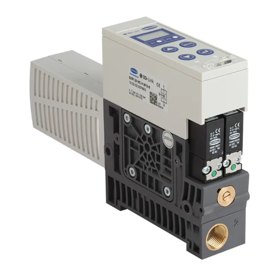
- Page 1 Innovative Vacuum for Automation Schmalz X-Pump – SXPi/SXMPi...
-
Page 2: Table Of Contents
/SXMP C H MA LZ ONTENTS Safety Instructions ....................1-5 Important symbols ..........................1-5 General safety instructions ....................... 1-5 Intended use ............................. 1-6 Installation and operation ......................... 1-7 Product Overview ....................2-8 General description of functions ...................... 2-8 Vacuum generation (picking up the workpiece) ................2-8 Blow-off (depositing the workpiece) .................... - Page 3 /SXMP C H MA LZ Diagnostics output .......................... 3-30 Status indicator when a condition monitoring function is active ............. 3-30 Diagnostics/analysis function ......................3-32 Evaluation of the leakage rate ......................3-33 Measurement of the evacuation time t ..................3-33 Measurement of the evacuation time t ..................
- Page 4 /SXMP C H MA LZ Maintenance ......................6-63 General maintenance ........................6-63 Exterior soiling ..........................6-63 Silencer............................6-63 Screw-in/press-in filters ........................6-63 Warranty, spare parts and wearing parts ..................6-63 Spare and wearing parts ........................ 6-64 Troubleshooting ..........................6-64 Accessories ............................6-64 Technical Data ......................
-
Page 5: Safety Instructions
/SXMP C H MA LZ AFETY NSTRUCTIONS MPORTANT SYMBOLS This symbol indicates important information and instructions. Caution! This symbol indicates a potentially dangerous situation. If it is not avoided, slight or minor injuries may result. Danger! This symbol indicates an immediate hazard. If it is not avoided, death or serious injuries may result. -
Page 6: Intended Use
/SXMP C H MA LZ No person may sit or stand in the danger zone while the machine or system is in automatic mode. Components may be installed by trained specialist personnel only. Specialist personnel must be familiar with current safety rules and requirements. For example, these apply to the use of components such as solenoid valves and pressure switches as well as to controllers used in devices, machines and systems. -
Page 7: Installation And Operation
/SXMP C H MA LZ NSTALLATION AND OPERATION For safe installation and trouble-free operation, please observe and comply with the following points: The ejector may only be operated using power supply units with protected extra-low voltage (PELV). The system must incorporate safe electrical cut- off of the power supply in compliance with EN60204. -
Page 8: Product Overview
/SXMP C H MA LZ RODUCT VERVIEW ENERAL DESCRIPTION OF FUNCTIONS ACUUM GENERATION PICKING UP THE WORKPIECE The ejector is designed for vacuum handling of parts in combination with suction systems. The Venturi nozzle is activated and deactivated via the suction signal input. In the NO version, the Venturi nozzle is deactivated when the suction input signal is present. -
Page 9: Blow-Off (Depositing The Workpiece)
/SXMP C H MA LZ DEPOSITING THE WORKPIECE In blow-off mode, the vacuum circuit of the ejector is supplied with compressed air. This ensures that the vacuum drops quickly, depositing the workpiece quickly as well. Blow-off mode can be controlled externally or internally. When controlled externally, blow-off mode is activated by the “blow-off”... -
Page 10: Versions
/SXMP C H MA LZ ERSIONS Each ejector has a specific item designation (e.g. SXMPi-20-NO-H-2xM12). The item designation can be broken down as follows: Perfomance Pneumatic Additional Electrical Type Idle position class connection function connection SXPi Horizontal Normally open Pressure control 1xM12, 8-pin SXMPi Quick change... -
Page 11: Electrical Connection
/SXMP C H MA LZ LECTRICAL CONNECTION The electrical connection comes in two designs: one M12 connector with 8 pins or two M12 connectors with 5 pins each. Both versions have three signal inputs and three signal outputs as well as pins for the supply voltage. -
Page 12: Ejector Design
/SXMP C H MA LZ JECTOR DESIGN ASIC MODEL The basic model of the ejector is designed as follows: Only screw unions with cylindrical G-threads can be used at pos. 7 and pos. 12. Max. tightening Position Description torque Operating and display elements Status indicator Valve status indicator Blow-off pilot valve –... -
Page 13: Expansion Modules
/SXMP C H MA LZ XPANSION MODULES The basic module can be modified and expanded using a variety of expansion modules. Position Description Basic module – NO suction valve...normally open Basic module – NC suction valve...normally closed Basic module – IMP suction valve...bistable via pulse Power blow-off module SXMP Horizontal pneumatic connection (1[P]= G3/8", 2[V]= G3/8") Quick-change pneumatic connection... -
Page 14: Operating And Display Elements
/SXMP C H MA LZ PERATING AND DISPLAY ELEMENTS The foil keypad with a three-digit display, a status indicator and 4 additional LEDs allows for very simple operation of the ejector. Position Description Display LEDs for threshold values H1/H2 MENU button ENTER button UP button DOWN button... - Page 15 /SXMP C H MA LZ TATUS INDICATOR FOR SYSTEM VACUUM During conventional suctions cycles, the status indicator shows the current level of the system vacuum relative to the switching points H1 and H2. The status indicator goes out after a conventional suction cycle is finished. Status indicator Vacuum level Rising vacuum:...
-
Page 16: Description Of Functions
/SXMP C H MA LZ ESCRIPTION OF UNCTIONS PERATING MODES The ejectors are differentiated according to their start position when in the idle state: NO (normally open), NC (normally closed) and IMP (impulse). When the ejector is connected to the power supply, the ejector is in automatic mode and ready for operation. - Page 17 /SXMP C H MA LZ A U T O M A T I C – M O D E Blow-off Suction Air-saving function [ctr = on]: Suction OFF Auto blow-off Vacuum H1 Venturi- Venturi- NC, NO, IMP: nozzle nozzle [bLo = J-t] Vacuum <...
-
Page 18: Control Concept For No Ejectors
/SXMP C H MA LZ ONTROL CONCEPT FOR EJECTORS „ Suction“ [IN1] „ Blow-off“ [IN2] „Suction“ Mode 0 bar „Blow-off“ Mode 0 bar ONTROL CONCEPT FOR EJECTORS „ Suction“ [IN1] „ Blow-off“ [IN2] „Suction“ Mode 0 bar „Blow-off“ Mode 0 bar ONTROL CONCEPT FOR EJECTORS >... -
Page 19: General Functions
/SXMP C H MA LZ ENERAL FUNCTIONS ANUAL MODE The output signals may change during set-up in manual mode. Ensure that the machine or system does not start moving as a result. Personal injury or damage to the ejector could result. Starting manual mode always switches the ejector to “pneumatically OFF”... -
Page 20: Set-Up Mode
/SXMP C H MA LZ This automatic exiting of manual mode due to changes in external signals can cause the object being handled to move (due to suction or blow-off). UP MODE Similar to manual mode, set-up mode can be used to locate and rectify leaks in the vacuum circuit because the valve protection function is deactivated and because the control function is not deactivated even if the control frequency increases. -
Page 21: Zero-Point Adjustment Of The Sensors (Calibration)
/SXMP C H MA LZ The threshold value HP1 and the corresponding hysteresis value can be set in the main [HP1] [hP1] menu under the menu items or via IO-Link. POINT ADJUSTMENT OF THE SENSORS CALIBRATION Because the internal sensors are subject to variations based on the manufacturing process, it is recommended to calibrate the sensors once the ejector is installed. -
Page 22: Control Shutoff
/SXMP C H MA LZ ONTROL WITH LEAK MONITORING This operating mode is the same as the previous mode, with the addition that the leakage rate within the system is measured and compared to the configurable limit value [-L-]. If the actual leakage rate exceeds the limit value more than twice in succession, the control function is deactivated and the ejector switches to continuous suction. -
Page 23: Blow-Off Modes
/SXMP C H MA LZ OFF MODES This function is used to switch among the three blow-off modes. [bLo] The function can be set in the configuration menu under the menu item or via IO- Link. XTERNALLY CONTROLLED BLOW The blow-off valve is controlled directly via the blow-off signal input. The ejector switches to blow-off mode for as long as the signal is present. -
Page 24: Selecting The Vacuum And Pressure Units
/SXMP C H MA LZ The three signal outputs can be switched independently using the menu items [o-1], [o-3] in the configuration menu, or via IO-Link. UTPUT TYPE The output type can be used to switch the signal outputs between PNP and NPN. All three signal outputs are switched together. -
Page 25: Switch-Off Delay For The Signal Outputs
/SXMP C H MA LZ NCH OF The vacuum and pressure values are displayed in inHg. The setting for this unit is [-iH]. The pressure display is only available on ejectors with a pressure sensor (SX(M)Pi – xx – PC – xx). WITCH OFF DELAY FOR THE SIGNAL OUTPUTS This function is used to set the switch-off delay for the signal outputs. -
Page 26: Reset To Factory Settings
/SXMP C H MA LZ A PIN is recommended because carrying out parameterization while the ejector is in operation can change the status of signal inputs and outputs. ESET TO FACTORY SETTINGS This function is used to reset the ejector to its factory settings. All switching points and configurations are reset to the factory settings. -
Page 27: Power Failure
/SXMP C H MA LZ OWER FAILURE All ejector types have an internal voltage monitor. If the supply voltage drops below the permitted threshold, the status of the ejector changes as follows: EJECTOR TYPE The ejector switches to suction mode EJECTOR TYPE The ejector switches to “pneumatically OFF”... -
Page 28: Condition Monitoring [Cm]
/SXMP C H MA LZ [CM] ONDITION MONITORING ONITORING THE VALVE SWITCHING FREQUENCY ([ctr = on] [ctr = onS]) and the leakage rate in If the air-saving function is activated the gripper system is high, the ejector is constantly switching between the “Venturi nozzle active”... -
Page 29: Monitoring Leakage
/SXMP C H MA LZ ONITORING LEAKAGE ([-L-] = onS), the drop in the vacuum level within a certain time is In control mode monitored (mbar/s). A distinction is made between two states. [-L-] [-L-] Leakage L < Leakage L > If the leakage rate is less than the set If the leakage rate is greater than the value [-L-]... -
Page 30: Diagnostics Output
/SXMP C H MA LZ If the dynamic pressure is greater than (H2 – h2) but less than H1, a warning message is issued. Bit 4 is activated in IO-Link parameter 0x0092 and a condition monitoring event is signaled by bit 6 in the process data input byte. The two condition monitoring functions for operating pressure and dynamic ... - Page 31 /SXMP C H MA LZ XAMPLES FOR THE STATUS INDICATOR System mode Status indicator Description Suction OFF Vacuum Suction ON Blow-off ON [mbar] H1 - H1-h1 - Status indicator shows the Normal mode Display level of the system vacuum switches off H2 - H2-h2 - Suction OFF...
-
Page 32: Diagnostics/Analysis Function
/SXMP C H MA LZ IAGNOSTICS ANALYSIS FUNCTION The SXPi/SXMPi measures the leakage rate in the vacuum system during every suction cycle. The ejector measures the drop in the vacuum per unit of time. This function is a unique tool for evaluating the leak-tightness of the entire system. The measured leakage value falls within one of four leakage ranges (see table). -
Page 33: Evaluation Of The Leakage Rate
/SXMP C H MA LZ The functions described below have no effect on the status indicator or the outputs. They are only for use via IO-Link VALUATION OF THE LEAKAGE RATE Similar to the diagnostics/analysis function (DAF), this parameter outputs the range of the average leakage during the last suction cycle. -
Page 34: Absolute Air Consumption Measurement
/SXMP C H MA LZ BSOLUTE AIR CONSUMPTION MEASUREMENT Ejectors with an integrated pressure sensor also offer an absolute air consumption measurement in addition to the percentual air consumption measurement. The actual air consumption of a suction cycle is calculated by taking into account the system pressure and the nozzle size. -
Page 35: Performance Calculation
/SXMP C H MA LZ The value is provided via IO-Link at the beginning of the next suction cycle. ERFORMANCE CALCULATION Similar to the quality assessment, the performance calculation is used to assess the system state. The measured dynamic pressure can be used as a measure of the performance of the gripper system. -
Page 36: Operating And Menu Concepts
/SXMP C H MA LZ PERATING AND ONCEPTS The unit is operated via four buttons on the foil keypad. Settings are made using software menus. The operating structure is divided into settings in the main menu and in the configuration menu. Configuring the ejector in the main menu is sufficient for standard applications. -
Page 37: Operating Mode Display
/SXMP C H MA LZ PERATING MODE DISPLAY Pressing the button displays the current operating mode. This is either standard SIO mode or IO-Link mode. Operating mode 3 sec The display returns to the vacuum display after 3 s. AIN MENU All settings for standard ejector applications can be read and changed using the main menu. -
Page 38: Setting The Parameters In The Main Menu
/SXMP C H MA LZ ETTING THE PARAMETERS IN THE MAIN MENU Briefly press the button to set the parameters in the main menu. Select the desired parameter using the buttons. Confirm by pressing the button. Change the value using the buttons. -
Page 39: Configuration Menu
/SXMP C H MA LZ ONFIGURATION MENU An extended configuration menu is available for applications with special requirements. The operating structure is as follows: Configuring the air-saving function Configuring the control shutoff Configuring the max. permitted evacuation time Configuring the max. permitted leakage Configuring the blow-off function... - Page 40 /SXMP C H MA LZ Configuring the signal output o-2 Configuring the signal output o-3 Configuring the signal type Configuring the vacuum & pressure units Filtering the output signals Configuring eco mode Locking the menus using a Resetting to factory settings 4-40...
-
Page 41: Setting The Parameters In The Configuration Menu
/SXMP C H MA LZ ETTING THE PARAMETERS IN THE CONFIGURATION MENU Press the button for longer than 3 s to set the parameters in the configuration menu. Select the desired parameter using the buttons. Confirm by pressing the button. -
Page 42: System Menu
/SXMP C H MA LZ YSTEM MENU A special menu is available for reading system data such as counter values, the article number and the serial numbers as well as the software versions. The operating structure is as follows: Counter 1 (erasable) X * 10 X * 10 >... -
Page 43: Displaying Counters
/SXMP C H MA LZ ISPLAYING COUNTERS Press and hold the buttons together for longer than 3 seconds to display the counters. buttons to select the desired counter from among [ct1], [ct2], Use the [ct3], [cc1], [cc2] or [cc3]. ... -
Page 44: Serial Number
/SXMP C H MA LZ ERIAL NUMBER The serial number indicates the period in which the ejector was manufactured. Press and hold the buttons together for longer than 3 seconds to display the serial number. [Snr] Use the buttons to select the function. -
Page 45: Operating Mode
/SXMP C H MA LZ PERATING All ejectors of the SX(M)Pi series have two operating modes. Users can choose between direct connection to inputs and outputs (serial I/O = SIO mode) or connection through the communication line (IO-Link). By default, the ejector always runs in SIO mode, but it can be switched in and out of IO- Link operating mode by the connected IO-Link master at any time. -
Page 46: Mounting
/SXMP C H MA LZ OUNTING SX(M)Pi – xx – H – xx SX(M)Pi – xx – Q – xx The following sequence must be observed when mounting the ejector on the quick- change system: Press release lever in all the way and hold it in place. ... -
Page 47: Electrical Connection
The lines for the power supply, the signal inputs and the signal outputs can have a maximum length of 30 meters. Direct connection Connection via I/O box Schmalz connection lines may be used to Schmalz connection distributors may be connect the ejector directly to the controller. used to connect the ejector to IO boxes. -
Page 48: Pin Assignment Of The Connection Plug
Blue Ground for sensor/actuator DAF signal input When Schmalz connection line is used, art. no. 21.04.05.00080 When Schmalz connection line is used, art. no. 21.04.05.00079 DAF analysis function: See the “Diagnostics/analysis function” section The system may only be operated using power supply units with protected extra-low voltage (PELV) and safe electrical cut-off of the operating voltage, in accordance with EN60204. -
Page 49: Project Planning
/SXMP C H MA LZ ROJECT PLANNING To operate the ejector in SIO mode, all process signals must be wired in parallel. Each ejector therefore requires six lines for the process signals. INPUT ROCESS DATA Signal Symbol Parameter OUT 1 Switching point H1/HP1 OUT 2 Switching point H2... -
Page 50: Warnings And Errors
/SXMP C H MA LZ ARNINGS AND ERRORS ARNINGS Events related to the condition monitoring functions are issued via output 3 of the ejector; these events provide information about the state of the process. See the “Condition monitoring” section. RROR Error messages from the ejector are shown in the display. -
Page 51: Io-Link Mode
/SXMP C H MA LZ IO-L INK MODE VERVIEW When operating the ejector in IO-Link mode (digital communication), only the power supply and the communication line must be connected to a controller directly or via intelligent connection boxes. The communication line for IO-Link (C/Q line) must always be connected to an IO-Link master port (point-to-point connection). -
Page 52: Mounting
/SXMP C H MA LZ OUNTING SX(M)Pi – xx – H – xx SX(M)Pi – xx – Q – xx The following sequence must be observed when mounting the ejector on the quick- change system: Press release lever in all the way and hold it in place ... -
Page 53: Electrical Connection
The lines for the power supply and IO-Link can have a maximum length of 20 m. Direct connection Connection via I/O-link master A Schmalz connection line may be used to A Schmalz connection line may be used to connect the ejector directly to the controller. -
Page 54: Pin Assignment Of The Connection Plug
Pink Blue Ground for sensor/actuator When Schmalz connection line is used, art. no. 21.04.05.00080 When Schmalz connection line is used, art. no. 21.04.05.00079 The system may only be operated using power supply units with protected extra-low voltage (PELV) and safe electrical cut-off of the operating voltage, in accordance with EN60204. -
Page 55: Project Planning
/SXMP C H MA LZ ROJECT PLANNING To operate the ejector in IO-Link mode, you only need to connect an IO-Link connection line (C/Q) in addition to the power supply. Each ejector therefore only requires one line for all process and parameter data. The following parameters apply for the physical interface: Parameter SIO mode... - Page 56 0x0008 0xEA 0x0009 3 bytes 0x01 0x000A Device ID 0x87 0x000B 0x73 0x0010 Vendor name 15 bytes J. Schmalz GmbH 0x0011 Vendor text 15 bytes www.schmalz.com 0x0012 Product name 32 bytes SXPi series 0x0013 Product ID 17 bytes 10.02.02.00000/00 0x0014...
- Page 57 /SXMP C H MA LZ 0 = Off 1 = 10ms 0x004B Output filter 1 byte 0 - 3 2 = 50ms 3 =200ms 0 = Eco OFF 0x004C Eco mode 1 byte 0 - 1 1 = Eco ON 0 = unlocked 0x004D 2 bytes...
- Page 58 /SXMP C H MA LZ – C ARAMETER DATA OUNTER SPDU Parameter Length Range Comment index Vacuum on 0 – 1·10 0x008C 4 bytes Not erasable counter Valve operating 0 – 1·10 0x008D 4 bytes Not erasable counter Condition monitoring 0 –...
- Page 59 An IODD file is required to incorporate the ejector into a controller. This is available for download at www.schmalz.com for the particular ejector type. If a Siemens controller is used, the IODD must be loaded using the PCT configuration tool and each IO-Link port must be configured.
-
Page 60: Start Of Operations
/SXMP C H MA LZ TART OF OPERATIONS The ejector is always in SIO mode after the supply voltage is applied. IO-Link communication is only established after a wake-up signal from the master. In order for the IO-Link master to establish communication, output OUT1 must be inactive and the ejector must be set to signal type PNP. - Page 61 /SXMP C H MA LZ [EM] NERGY MONITORING All EM values are available for the previous suction cycle after the next suction cycle has begun; they must therefore be read out after every “Suction ON” command. [PM] REDICTIVE MAINTENANCE All PM values are available for the previous suction cycle after the next suction cycle has begun;...
-
Page 62: Warnings And Errors
/SXMP C H MA LZ ARNINGS AND ERRORS ARNINGS Warnings, especially those that are the result of condition monitoring functions, provide information about the state of the vacuum system and the current handling cycle. See the “Condition monitoring” section. Condition monitoring events that arise in the ejector are signaled via bit 6 in the process data byte input (PDI). -
Page 63: Maintenance
/SXMP C H MA LZ AINTENANCE ENERAL MAINTENANCE XTERIOR SOILING Remove dirt on the exterior of the device with a soft cloth and soap suds (max. 60°C). Ensure that the silencer and the controller are not soaked with soap suds. ILENCER Because it is open, the silencer may be exposed to high levels of dust, oil, etc., which may dirty the silencer to the point of reducing the suction capacity. -
Page 64: Spare And Wearing Parts
/SXMP C H MA LZ PARE AND WEARING PARTS Type Designation Article no. Legend Silencer 10.02.02.02124 Base plate GP 2 Screw-in filter 3/8" thread 10.05.03.00013 SXPi/SXMPi…H Filter, 17.5x2 10.02.02.03378 …NO… Suction valve for NO ejector (NO valve) 10.05.01.00278 …NC… Suction valve for NC ejector (NC valve) 10.05.01.00277 …IMP…... -
Page 65: Technical Data
/SXMP C H MA LZ ECHNICAL Operating the ejector system outside of the specified values can result in damage to the system and attached components. LECTRICAL PARAMETERS Limit values Sym- Parameter Units Comment Min. Max. Supply voltage 19.2 26.4 PELV SX(M)Pi –... -
Page 66: Display Parameters
/SXMP C H MA LZ ISPLAY PARAMETERS Parameter Value Unit Comment Display Digits Red 7-segment LED Resolution Digits Unit = mbar Accuracy % FS = 25 °C, based on FS end value (full scale) Linearity error Offset error Digits After zero-point adjustment, without vacuum (unit = mbar) -
Page 67: Materials Used
/SXMP C H MA LZ ATERIALS USED Component Material Basic body PA6-GF Anodized aluminum alloy, brass, galvanized steel, Inner components stainless steel, PU, POM Controller housing PC, PMMA Pneumatic connection adapter Q Anodized aluminum allow, galvanized steel Pneumatic connection adapter H PA6-GF Silencer housing Silencer insert... - Page 68 /SXMP C H MA LZ SXPi / SXMPi...Q... Type SXPi...H 3/8" 134 54 210 5 SXPi...Q 121 54 210 5 SXMPi…H 39 3/8" 160 54 210 5 SXMPi…Q 39 147 54 210 5 Base plate GP2 Type 3/8" 7-68...
-
Page 69: Pneumatic Circuit Diagrams
/SXMP C H MA LZ NEUMATIC CIRCUIT DIAGRAMS SXMPi...NO... SXMPi...NC... SXMPi…IMP... SXMPi… IMP-PC 7-69... - Page 70 /SXMP C H MA LZ SXPi...NO... SXPi...NC... SXPi...IMP... SXPi...IMP-PC 7-70...
-
Page 71: Overview Of Display Symbols
/SXMP C H MA LZ VERVIEW OF DISPLAY SYMBOLS Symbol Function Comment Switching point H1 Switch-off value for the air-saving function Hysteresis h1 Hysteresis of the air-saving function Switch-on value for the “part present control” signal output Switching point H2 (when NO output is configured) Hysteresis of “part present control”... - Page 72 /SXMP C H MA LZ Vacuum value (in kPa) The vacuum and pressure values are displayed in kPa. Vacuum value in inHg The vacuum and pressure values are displayed in inHg. Evacuation time Setting for the maximum permitted evacuation time Leakage value Setting for the maximum permitted leakage Switch-off delay...
-
Page 73: Factory Settings
/SXMP C H MA LZ Menu locked A lock prevents parameters from being changed. Menu unlocked The buttons and menus are unlocked. ACTORY SETTINGS Symbol Function Factory setting Switching point H1 750 mbar Hysteresis h1 150 mbar Switching point H2 550 mbar Hysteresis h2 10 mbar... -
Page 74: Conformity Declaration
/SXMP C H MA LZ ONFORMITY ECLARATION 8-74... - Page 75 We reserve the right to make technical changes. No responsibility is taken for print errors or other types of errors. All information and specifications are subject to change without notice. © J. Schmalz GmbH. All rights reserved. 30.30.01.00016-EN Last updated: 02/2017 / Index 02...
- Page 76 Fax +34 94 4807264 schmalz@schmalz.co.in schmalz@schmalz.es Italy Tel.+39 0321 621510 Fax+39 0321 621714 schmalz@schmalz.it 30.30.01.00016-EN J. Schmalz GmbH Aacher Strasse 29 Last update: 02/2017 Index: 02 D-72293 Glatten Tel. +49 (0)7443 2403 0 Fax +49 (0)7443 2403 259 schmalz@schmalz.de www.schmalz.com...
Need help?
Do you have a question about the IO-Link X-Pump SXPi Series and is the answer not in the manual?
Questions and answers