Juniper SRX5400 Hardware Manual
Services gateway
Hide thumbs
Also See for SRX5400:
- Hardware manual (438 pages) ,
- Reference (109 pages) ,
- Manual (102 pages)

Related Manuals for Juniper SRX5400


Summary of Contents for Juniper SRX5400
- Page 1 SRX5400 Services Gateway Hardware Guide Published: 2014-01-09 Copyright © 2014, Juniper Networks, Inc.
- Page 2 END USER LICENSE AGREEMENT The Juniper Networks product that is the subject of this technical documentation consists of (or is intended for use with) Juniper Networks software. Use of such software is subject to the terms and conditions of the End User License Agreement (“EULA”) posted at http://www.juniper.net/support/eula.html.
-
Page 3: Table Of Contents
SRX5400 Services Gateway Chassis ........ - Page 4 Tools and Parts Required to Unpack the SRX5400 Services Gateway ..43 Unpacking the SRX5400 Services Gateway ......43 Verifying the SRX5400 Services Gateway Parts Received .
- Page 5 Connections ........... 63 Grounding the SRX5400 Services Gateway ......64 Connecting Power to an AC-Powered SRX5400 Services Gateway .
- Page 6 SRX5400 Services Gateway FRUs ........
- Page 7 SRX5400 Services Gateway General Safety Guidelines and Warnings ..151 Additional SRX5400 Services Gateway Warnings ......152 Qualified Personnel Warning .
- Page 8 Signal Loss in Multimode and Single-Mode Fiber-Optic Cable for the SRX5400 Services Gateway ........203 Attenuation and Dispersion in Fiber-Optic Cable for the SRX5400 Services Gateway .
- Page 9 SRX5400 Services Gateway ........
- Page 10 SRX5400 Services Gateway Hardware Guide Part 5 Index Index ............231...
-
Page 11: About The Documentation
® To obtain the most current version of all Juniper Networks technical documentation, see the product documentation page on the Juniper Networks website at http://www.juniper.net/techpubs/ If the information in the latest release notes differs from the information in the documentation, follow the product Release Notes. - Page 12 SRX5400 Services Gateway Hardware Guide Table 1: Notice Icons Icon Meaning Description Informational note Indicates important features or instructions. Caution Indicates a situation that might result in loss of data or hardware damage. Warning Alerts you to the risk of personal injury or death.
-
Page 13: Documentation Feedback
Software release version (if applicable) Requesting Technical Support Technical product support is available through the Juniper Networks Technical Assistance Center (JTAC). If you are a customer with an active J-Care or JNASC support contract, Copyright © 2014, Juniper Networks, Inc. -
Page 14: Self-Help Online Tools And Resources
7 days a week, 365 days a year. Self-Help Online Tools and Resources For quick and easy problem resolution, Juniper Networks has designed an online self-service portal called the Customer Support Center (CSC) that provides you with the following features: Find CSC offerings: http://www.juniper.net/customers/support/... -
Page 15: Srx5400 Services Gateway Overview
PART 1 SRX5400 Services Gateway Overview Introduction to the SRX5400 Services Gateway on page 3 SRX5400 Services Gateway Hardware Components on page 7 Copyright © 2014, Juniper Networks, Inc. - Page 16 SRX5400 Services Gateway Hardware Guide Copyright © 2014, Juniper Networks, Inc.
-
Page 17: Introduction To The Srx5400 Services Gateway
The SRX5400 Services Gateway is 5 rack units (U) tall. You can stack eight services gateways in a rack that is at least 48 U (89.3 in. or 2.24 m) in height if it has a 1 in. cap between for increased port density per unit of floor space. -
Page 18: Srx5400 Services Gateway Physical Specifications
SRX5400 Services Gateway Physical Specifications on page 4 Documentation SRX5400 Services Gateway Chassis on page 7 SRX5400 Services Gateway Card Cage and Slots on page 9 SRX5400 Services Gateway Component Redundancy on page 5 SRX5400 Services Gateway Physical Specifications Table 3 on page 4 summarizes the physical specifications for the services gateway chassis. -
Page 19: Srx5400 Services Gateway Component Redundancy
SRX5400 Services Gateway Description on page 3 Documentation SRX5400 Services Gateway Chassis on page 7 SRX5400 Services Gateway Card Cage and Slots on page 9 SRX5400 Services Gateway Component Redundancy on page 5 SRX5400 Services Gateway Component Redundancy The following major hardware components are redundant: Power supplies—In the low-line (110 V) AC power configuration, the device contains... - Page 20 Related SRX5400 Services Gateway Description on page 3 Documentation SRX5400 Services Gateway Physical Specifications on page 4 SRX5400 Services Gateway Chassis on page 7 SRX5400 Services Gateway Card Cage and Slots on page 9 Copyright © 2014, Juniper Networks, Inc.
-
Page 21: Srx5400 Services Gateway Hardware Components
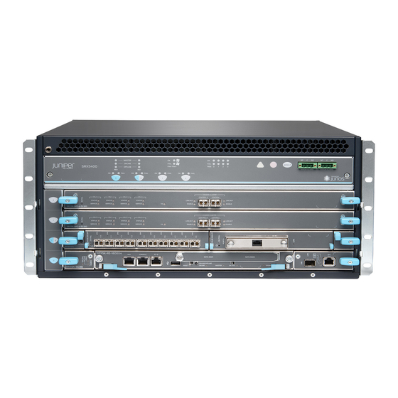
CHAPTER 2 SRX5400 Services Gateway Hardware Components Nearly all components of the SRX5400 Services Gateway are field-replaceable units (FRUs), including the Switch Control Board (SCB), Routing Engine (RE), Services Processing Cards (SPCs), Modular PIC Concentrators (MPCs), the power supplies, the fan tray, and the air filter. - Page 22 SRX5400 Services Gateway Hardware Guide around your bare wrist. Failure to use an ESD strap can result in damage to the services gateway. WARNING: The services gateway must be connected to earth ground during normal operation. Figure 1: Front View of a Fully Configured Services Gateway Chassis...
-
Page 23: Srx5400 Services Gateway Card Cage And Slots
Chapter 2: SRX5400 Services Gateway Hardware Components Figure 3: Rear View of a Fully Configured DC-Powered Services Gateway Chassis Related Preventing Electrostatic Discharge Damage to the SRX5400 Services Gateway on Documentation page 155 SRX5400 Services Gateway Physical Specifications on page 4... -
Page 24: Srx5400 Services Gateway Midplane Description
The SRX5400 Services Gateway does not support the I/O cards (IOCs) or Flex IOCs supported by the SRX5600 and SRX5800 Services Gateways. MPCs are the only supported interface cards for the SRX5400 Services Gateway. If a slot in the card cage is not occupied by a card, you must install a blank panel to shield the empty slot and to allow cooling air to circulate properly through the services gateway. -
Page 25: Srx5400 Services Gateway Spc Description
Documentation Installing an SRX5400 Services Gateway MIC on page 126 Maintaining SPCs and MPCs on the SRX5400 Services Gateway on page 84 Troubleshooting SRX5400 Services Gateway MPCs on page 97 SRX5400 Services Gateway Card Cage and Slots on page 9... -
Page 26: Srx5400 Services Gateway Host Subsystem Description
Installing an SRX5400 Services Gateway SPC on page 133 Documentation SRX5400 Services Gateway Card Cage and Slots on page 9 Maintaining SPCs and MPCs on the SRX5400 Services Gateway on page 84 Troubleshooting SRX5400 Services Gateway SPCs on page 99 SRX5400 Services Gateway FRUs on page 103... -
Page 27: Srx5400 Services Gateway Scb Description
SRX5400, SRX5600, and SRX5800 Services Gateway Card Reference www.juniper.net/techpubs/ Related SRX5400 Services Gateway Card Cage and Slots on page 9 Documentation Maintaining the SRX5400 Services Gateway Host Subsystem on page 83 Replacing the SRX5400 Services Gateway SCB on page 113... -
Page 28: Srx5400 Services Gateway Routing Engine Description
SRX5400 Services Gateway Craft Interface SRX5400 Services Gateway Craft Interface Overview on page 15 SRX5400 Services Gateway Craft Interface Alarm LEDs and Alarm Cutoff/Lamp Test Button on page 16 SRX5400 Services Gateway Craft Interface Host Subsystem LEDs on page 17... -
Page 29: Srx5400 Services Gateway Craft Interface
Chapter 2: SRX5400 Services Gateway Hardware Components SRX5400 Services Gateway Craft Interface Overview The craft interface shows you status and troubleshooting information at a glance and lets you perform many system control functions. It is hot-insertable and hot-removable. The craft interface is located on the front of the services gateway above the upper fan tray. - Page 30 SRX5400 Services Gateway Chassis on page 7 SRX5400 Services Gateway Card Cage and Slots on page 9 SRX5400 Services Gateway Craft Interface Alarm LEDs and Alarm Cutoff/Lamp Test Button Two large alarm LEDs are located at the upper right of the craft interface. The circular red LED lights to indicate a major alarm condition that can result in a system shutdown.
- Page 31 SRX5400 Services Gateway Craft Interface Overview on page 15 Documentation SRX5400 Services Gateway Craft Interface Alarm Relay Contacts on page 21 SRX5400 Services Gateway Craft Interface Host Subsystem LEDs on page 17 SRX5400 Services Gateway Craft Interface Host Subsystem LEDs The host subsystem has three LEDs, located on the upper left of the craft interface, that indicate its status.
- Page 32 SRX5400 Services Gateway Craft Interface Overview on page 15 Documentation SRX5400 Services Gateway Craft Interface Host Subsystem LEDs on page 17 SRX5400 Services Gateway Craft Interface Card OK/Fail LEDs on page 18 SRX5400 Services Gateway Craft Interface Card OK/Fail LEDs Each slot in the card cage has a pair of LEDs on the craft interface that indicates the status of the card installed in it.
- Page 33 Related SRX5400 Services Gateway Craft Interface Overview on page 15 Documentation SRX5400 Services Gateway Craft Interface Card OK/Fail LEDs on page 18 SRX5400 Services Gateway Craft Interface Online/Offline Buttons on page 19 SRX5400 Services Gateway Craft Interface Online/Offline Buttons The craft interface has a row of Online/Offline buttons along its lower edge. Each button corresponds to one slot in the card cage.
- Page 34 SRX5400 Services Gateway Hardware Guide user@host> request chassis fpc slot 2 offline node0: -------------------------------------------------------------------------- Offline initiated, use "show chassis fpc" to verify {primary:node0} user@host> show chassis fpc node0: -------------------------------------------------------------------------- Temp CPU Utilization (%) Memory Utilization (%) Slot State Total Interrupt...
- Page 35 Documentation SRX5400 Services Gateway Craft Interface Fan LEDs on page 19 SRX5400 Services Gateway Craft Interface Alarm Relay Contacts on page 21 SRX5400 Services Gateway Craft Interface Alarm Relay Contacts The craft interface has two alarm relay contacts for connecting the device to external...
-
Page 36: Srx5400 Services Gateway Power System Description
Connecting the Alarm Relay Wires to the SRX5400 Services Gateway Craft Interface on page 108 Alarm Relay Contact Wire Specifications for the SRX5400 Services Gateway on page 207 SRX5400 Services Gateway Power System Description SRX5400 Services Gateway Power System Overview on page 23... - Page 37 For detailed power supply specifications, see “SRX5400 Services Gateway AC Power Supply Specifications” on page 194 “SRX5400 Services Gateway DC Power Supply Specifications” on page 197. Table 13: Power Supply Type Summary Power Supply...
- Page 38 SRX5400 Services Gateway AC Power Supply LEDs on page 25 Troubleshooting the SRX5400 Services Gateway Power System on page 101 Replacing an SRX5400 Services Gateway AC Power Supply on page 137 SRX5400 Services Gateway AC Power Supply Specifications on page 194...
-
Page 39: Srx5400 Services Gateway Ac Power Supply
LEDs for more information. AC OK DC OK Related SRX5400 Services Gateway Power System Overview on page 23 Documentation SRX5400 Services Gateway AC Power Supply on page 24 SRX5400 Services Gateway DC Power Supply Each DC power supply consists of one DC input (–48 VDC and return), one 40 A (–48 VDC) circuit breaker, a fan, and LEDs to monitor the status of the power supply. -
Page 40: Srx5400 Services Gateway Dc Power Supply Leds
SRX5400 Services Gateway DC Power Supply LEDs on page 26 Troubleshooting the SRX5400 Services Gateway Power System on page 101 Removing an SRX5400 Services Gateway DC Power Supply on page 139 SRX5400 Services Gateway DC Power Supply Specifications on page 197... -
Page 41: Srx5400 Services Gateway Cooling System Description
DC input is present, but not in valid operating range or connected in reverse polarity. Related SRX5400 Services Gateway Craft Interface Power Supply LEDs on page 18 Documentation SRX5400 Services Gateway Power System Overview on page 23 SRX5400 Services Gateway DC Power Supply on page 25... - Page 42 SRX5400 Services Gateway Hardware Guide Figure 13: Airflow Through the Chassis The host subsystem monitors the temperature of the services gateway components. When the device is operating normally, the fans function at lower than full speed. If a fan fails or the ambient temperature rises above a threshold, the speed of the remaining fans is automatically adjusted to keep the temperature within the acceptable range.
- Page 43 Chapter 2: SRX5400 Services Gateway Hardware Components Related Maintaining the Fan Tray on the SRX5400 Services Gateway on page 82 Documentation Maintaining the Air Filter on the SRX5400 Services Gateway on page 82 Troubleshooting the SRX5400 Services Gateway Cooling System on page 96...
- Page 44 SRX5400 Services Gateway Hardware Guide Copyright © 2014, Juniper Networks, Inc.
-
Page 45: Setting Up The Srx5400 Services Gateway
Setting Up the SRX5400 Services Gateway SRX5400 Services Gateway Installation on page 33 Preparing the Site for the SRX5400 Services Gateway Installation on page 35 Unpacking the SRX5400 Services Gateway on page 43 Installing the SRX5400 Services Gateway Mounting Hardware on page 47... - Page 46 SRX5400 Services Gateway Hardware Guide Copyright © 2014, Juniper Networks, Inc.
-
Page 47: Srx5400 Services Gateway Installation
Installing the SRX5400 Services Gateway Using a Mechanical Lift on page 53 Installing the SRX5400 Services Gateway Chassis in the Rack Manually on page 216 Connect cables to the network and external devices. - Page 48 Connect the AC power cord or DC power cables: Connecting Power to an AC-Powered SRX5400 Services Gateway on page 65 Connecting Power to a DC-Powered SRX5400 Services Gateway on page 67 Power on the services gateway:...
-
Page 49: Preparing The Site For The Srx5400 Services Gateway Installation
CHAPTER 4 Preparing the Site for the SRX5400 Services Gateway Installation Site Preparation Checklist for the SRX5400 Services Gateway on page 35 SRX5400 Services Gateway Rack Requirements on page 36 SRX5400 Services Gateway Cabinet Requirements on page 40 Site Preparation Checklist for the SRX5400 Services Gateway... -
Page 50: Srx5400 Services Gateway Rack Requirements
SRX5400 Services Gateway” on page 205,“Calculating Power Margin for Fiber-Optic Cable for the SRX5400 Services Gateway” on page 205 Related Overview of Installing the SRX5400 Services Gateway on page 33 Documentation Unpacking the SRX5400 Services Gateway on page 43 SRX5400 Services Gateway Rack Requirements The services gateway can be installed in a rack. -
Page 51: Srx5400 Services Gateway Rack Size And Strength Requirements
The rack requirements are described in the following topics: SRX5400 Services Gateway Rack Size and Strength Requirements on page 37 Spacing of Rack Mounting Bracket Holes for the SRX5400 Services Gateway on page 38 Connection to Building Structure for the SRX5400 Services Gateway Rack on page 39... - Page 52 Documentation Site Preparation Checklist for the SRX5400 Services Gateway on page 35 Spacing of Rack Mounting Bracket Holes for the SRX5400 Services Gateway on page 38 Connection to Building Structure for the SRX5400 Services Gateway Rack on page 39 Clearance Requirements for SRX5400 Services Gateway Airflow and Hardware...
- Page 53 Overview of Installing the SRX5400 Services Gateway on page 33 Documentation SRX5400 Services Gateway Rack Size and Strength Requirements on page 37 Spacing of Rack Mounting Bracket Holes for the SRX5400 Services Gateway on page 38 Clearance Requirements for SRX5400 Services Gateway Airflow and Hardware Maintenance on page 39...
-
Page 54: Srx5400 Services Gateway Cabinet Requirements
Documentation Site Preparation Checklist for the SRX5400 Services Gateway on page 35 Spacing of Rack Mounting Bracket Holes for the SRX5400 Services Gateway on page 38 SRX5400 Services Gateway Cabinet Airflow Requirements on page 40 SRX5400 Services Gateway Cabinet Airflow Requirements When you mount the device in a cabinet, you must ensure that ventilation through the cabinet is sufficient to prevent overheating. - Page 55 Chapter 4: Preparing the Site for the SRX5400 Services Gateway Installation Site Preparation Checklist for the SRX5400 Services Gateway on page 35 Spacing of Rack Mounting Bracket Holes for the SRX5400 Services Gateway on page 38 SRX5400 Services Gateway Cabinet Size and Clearance Requirements on page 40...
- Page 56 SRX5400 Services Gateway Hardware Guide Copyright © 2014, Juniper Networks, Inc.
-
Page 57: Unpacking The Srx5400 Services Gateway
CHAPTER 5 Unpacking the SRX5400 Services Gateway Tools and Parts Required to Unpack the SRX5400 Services Gateway on page 43 Unpacking the SRX5400 Services Gateway on page 43 Verifying the SRX5400 Services Gateway Parts Received on page 45 Tools and Parts Required to Unpack the SRX5400 Services Gateway... - Page 58 Figure 18: Contents of the Shipping Crate Related Tools and Parts Required to Unpack the SRX5400 Services Gateway on page 43 Documentation Overview of Installing the SRX5400 Services Gateway on page 33...
-
Page 59: Verifying The Srx5400 Services Gateway Parts Received
Chapter 5: Unpacking the SRX5400 Services Gateway Verifying the SRX5400 Services Gateway Parts Received A packing list is included in each shipment. Check the parts in the shipment against the items on the packing list. The packing list specifies the part numbers and descriptions of each part in your order. - Page 60 Overview of Installing the SRX5400 Services Gateway on page 33 Documentation Site Preparation Checklist for the SRX5400 Services Gateway on page 35 Tools and Parts Required to Unpack the SRX5400 Services Gateway on page 43 Unpacking the SRX5400 Services Gateway on page 43 Copyright © 2014, Juniper Networks, Inc.
-
Page 61: Installing The Srx5400 Services Gateway Mounting Hardware
CHAPTER 6 Installing the SRX5400 Services Gateway Mounting Hardware Tools and Parts Required to Install the SRX5400 Services Gateway Mounting Hardware for a Rack or Cabinet on page 47 Installing the SRX5400 Services Gateway Mounting Hardware for a Rack or... - Page 62 SRX5400 Services Gateway Hardware Guide Table 19: Four-Post Rack or Cabinet Mounting Hole Locations (continued) Hole Distance Above U Division 0.88 in. (2.2 cm) 0.50 U 0.25 in. (0.6 cm) 0.14 U To install the mounting shelf on the front rails of a four-post rack or cabinet, or the rails...
- Page 63 Chapter 6: Installing the SRX5400 Services Gateway Mounting Hardware Figure 19: Installing the Front Mounting Hardware for a Four-Post Rack or Cabinet Copyright © 2014, Juniper Networks, Inc.
- Page 64 SRX5400 Services Gateway Hardware Guide Figure 20: Installing the Mounting Hardware for an Open-Frame Rack Related Tools and Parts Required to Install the SRX5400 Services Gateway Mounting Hardware Documentation for a Rack or Cabinet on page 47 Overview of Installing the SRX5400 Services Gateway on page 33...
- Page 65 Overview of Installing the SRX5400 Services Gateway on page 33 Documentation Site Preparation Checklist for the SRX5400 Services Gateway on page 35 Tools Required to Install the SRX5400 Services Gateway with a Mechanical Lift on page 53 Unpacking the SRX5400 Services Gateway on page 43 Installing the SRX5400 Services Gateway Using a Mechanical Lift on page 53 Copyright ©...
- Page 66 SRX5400 Services Gateway Hardware Guide Copyright © 2014, Juniper Networks, Inc.
-
Page 67: Tools Required To Install The Srx5400 Services Gateway With A Mechanical
Tools Required to Install the SRX5400 Services Gateway with a Mechanical Lift on page 53 Installing the SRX5400 Services Gateway Using a Mechanical Lift on page 53 Tools Required to Install the SRX5400 Services Gateway with a Mechanical Lift To install the services gateway, you need the following tools:... - Page 68 SRX5400 Services Gateway Hardware Guide Using the lift, position the services gateway in front of the rack or cabinet, centering it in front of the mounting shelf. Lift the chassis approximately 0.75 in. above the surface of the mounting shelf and position it as close as possible to the shelf.
- Page 69 Site Preparation Checklist for the SRX5400 Services Gateway on page 35 Unpacking the SRX5400 Services Gateway on page 43 Tools and Parts Required for SRX5400 Services Gateway Connections on page 57 Overview of Installing the SRX5400 Services Gateway on page 33...
- Page 70 SRX5400 Services Gateway Hardware Guide Copyright © 2014, Juniper Networks, Inc.
-
Page 71: Connecting The Srx5400 Services Gateway
CHAPTER 8 Connecting the SRX5400 Services Gateway Tools and Parts Required for SRX5400 Services Gateway Connections on page 57 Connecting the SRX5400 Services Gateway to Management and Alarm Devices on page 58 Tools and Parts Required for SRX5400 Services Gateway Connections... -
Page 72: Connecting The Srx5400 Services Gateway To A Management Console Or An Auxiliary Device
Connecting the SRX5400 Services Gateway to Management and Alarm Devices Connecting the SRX5400 Services Gateway to a Network for Out-of-Band Management on page 58 Connecting the SRX5400 Services Gateway to a Management Console or an Auxiliary Device on page 59 Connecting an SRX5400 Services Gateway to an External Alarm-Reporting... - Page 73 Chapter 8: Connecting the SRX5400 Services Gateway Connecting the SRX5400 Services Gateway to a Management Console or an Auxiliary Device To use a system console to configure and manage the Routing Engine, connect it to the appropriate CONSOLE port on the Routing Engine. To use a laptop, modem, or other auxiliary device, connect it to the port on the Routing Engine.
-
Page 74: Connecting Network Cables To Srx5400 Services Gateway Mics
SRX5400 Services Gateway Hardware Guide Connecting an SRX5400 Services Gateway to an External Alarm-Reporting Device on page 60 Connecting Network Cables to SRX5400 Services Gateway MICs on page 61 Connecting an SRX5400 Services Gateway to an External Alarm-Reporting Device To connect the services gateway to external alarm-reporting devices, attach wires to... - Page 75 Attach the other end of the wires to the external device. To attach a reporting device for the other kind of alarm, repeat the procedure. Related Tools and Parts Required for SRX5400 Services Gateway Connections on page 57 Documentation Overview of Installing the SRX5400 Services Gateway on page 33...
- Page 76 Related Tools and Parts Required for SRX5400 Services Gateway Connections on page 57 Documentation Overview of Installing the SRX5400 Services Gateway on page 33...
-
Page 77: Grounding And Providing Power To The Srx5400 Services Gateway
CHAPTER 9 Grounding and Providing Power to the SRX5400 Services Gateway Tools and Parts Required for SRX5400 Services Gateway Grounding and Power Connections on page 63 Grounding the SRX5400 Services Gateway on page 64 Connecting Power to an AC-Powered SRX5400 Services Gateway on page 65... -
Page 78: Grounding The Srx5400 Services Gateway
Dress the grounding cable and verify that it does not touch or block access to device components, and that it does not drape where people could trip on it. Related Preventing Electrostatic Discharge Damage to the SRX5400 Services Gateway on Documentation page 155... -
Page 79: Connecting Power To An Ac-Powered Srx5400 Services Gateway
Chapter 9: Grounding and Providing Power to the SRX5400 Services Gateway Overview of Installing the SRX5400 Services Gateway on page 33 Tools and Parts Required for SRX5400 Services Gateway Grounding and Power Connections on page 63 Connecting Power to an AC-Powered SRX5400 Services Gateway on page 65... -
Page 80: Powering On An Ac-Powered Srx5400 Services Gateway
SRX5400 Services Gateway Hardware Guide Figure 29: Connecting AC Power to the Services Gateway Related AC Power Cord Specifications for the SRX5400 Services Gateway on page 195 Documentation Preventing Electrostatic Discharge Damage to the SRX5400 Services Gateway on page 155... -
Page 81: Connecting Power To A Dc-Powered Srx5400 Services Gateway
Chapter 9: Grounding and Providing Power to the SRX5400 Services Gateway installed and functioning normally, the LEDs light steadily, and the AC OK DC OK LED is not lit. PS FAIL If any of the status LEDs indicates that the power supply is not functioning normally, repeat the installation and cabling procedures. - Page 82 See “Grounding the SRX5400 Services Gateway” on page 64 for instructions. CAUTION: Do not mix AC and DC power supplies within the same services gateway.
- Page 83 Chapter 9: Grounding and Providing Power to the SRX5400 Services Gateway The cable with very low resistance (indicating a closed circuit) to chassis ground is CAUTION: You must ensure that power connections maintain the proper polarity. The power source cables might be labeled to indicate (–)
-
Page 84: Powering On A Dc-Powered Srx5400 Services Gateway
Documentation page 155 Overview of Installing the SRX5400 Services Gateway on page 33 Tools and Parts Required for SRX5400 Services Gateway Grounding and Power Connections on page 63 Grounding the SRX5400 Services Gateway on page 64 Powering On a DC-Powered SRX5400 Services Gateway on page 70... - Page 85 Chapter 9: Grounding and Providing Power to the SRX5400 Services Gateway If power is not present: Verify that the fuse is installed correctly and turn on the breaker at the battery distribution fuse board or fuse bay. Check the voltage with a meter at the terminals of the power supply for correct voltage level and polarity.
-
Page 86: Powering Off The Srx5400 Services Gateway
). On a DC-powered services gateway, switch the circuit breaker on each power supply to the off position ( Related Preventing Electrostatic Discharge Damage to the SRX5400 Services Gateway on Documentation page 155 Overview of Installing the SRX5400 Services Gateway on page 33... -
Page 87: Configuring Junos Os For The Srx5400 Services Gateway
CHAPTER 10 Configuring Junos OS for the SRX5400 Services Gateway SRX5400 Services Gateway Software Configuration Overview on page 73 Initially Configuring the SRX5400 Services Gateway on page 74 SRX5400 Services Gateway Software Configuration Overview The services gateway is shipped with the Junos operating system (Junos OS) preinstalled and ready to be configured when the device is powered on. -
Page 88: Initially Configuring The Srx5400 Services Gateway
SRX5400 Services Gateway Hardware Guide Initially Configuring the SRX5400 Services Gateway This procedure connects the device to the network but does not enable it to forward traffic. For complete information about enabling the device to forward traffic, including examples, see the appropriate Junos OS configuration guides. - Page 89 Chapter 10: Configuring Junos OS for the SRX5400 Services Gateway Configure the traffic interface. [edit] admin@# set interfaces xe-2/0/0 unit 0 family inet address address/prefix-length admin@# set interfaces xe-2/2/5 unit 0 family inet address address/prefix-length Configure the default route. [edit] admin@# set routing-options static route 0.0.0.0/0 next-hop gateway...
- Page 90 SRX5400 Services Gateway Hardware Guide interface xe-0/0/0.0; syslog { user * { any emergency; file messages { any any; authorization info; file interactive-commands { interactive-commands any; license { autoupdate { url https://ae1.juniper.net/junos/key_retrieval; interfaces { xe-0/0/0 { unit 0; xe-2/0/0 {...
- Page 91 Chapter 10: Configuring Junos OS for the SRX5400 Services Gateway interfaces { xe-2/0/0.0; policies { from-zone trust to-zone untrust { policy bob { match { source-address any; destination-address any; application any; then { permit; Commit the configuration to activate it on the device.
- Page 92 SRX5400 Services Gateway Hardware Guide Copyright © 2014, Juniper Networks, Inc.
- Page 93 SRX5400 Services Gateway Hardware Maintenance, Replacement, and Troubleshooting Procedures Maintaining the SRX5400 Services Gateway Hardware Components on page 81 Troubleshooting the SRX5400 Services Gateway Hardware Components on page 93 Replacing SRX5400 Services Gateway Hardware Components on page 103 Copyright © 2014, Juniper Networks, Inc.
- Page 94 SRX5400 Services Gateway Hardware Guide Copyright © 2014, Juniper Networks, Inc.
-
Page 95: Maintaining The Srx5400 Services Gateway Hardware Components
Maintaining the SRX5400 Services Gateway Hardware Components Tools and Parts Required to Maintain the SRX5400 Services Gateway on page 81 Routine Maintenance Procedures for the SRX5400 Services Gateway on page 81 Maintaining the Air Filter on the SRX5400 Services Gateway on page 82... -
Page 96: Maintaining The Air Filter On The Srx5400 Services Gateway
Routine Maintenance Procedures for the SRX5400 Services Gateway on page 81 Documentation Tools and Parts Required to Maintain the SRX5400 Services Gateway on page 81 Replacing the SRX5400 Services Gateway Air Filter on page 110 Maintaining the Fan Tray on the SRX5400 Services Gateway on page 82... -
Page 97: Maintaining The Srx5400 Services Gateway Host Subsystem
Routine Maintenance Procedures for the SRX5400 Services Gateway on page 81 Documentation Tools and Parts Required to Maintain the SRX5400 Services Gateway on page 81 Replacing the SRX5400 Services Gateway Fan Tray on page 108 Maintaining the SRX5400 Services Gateway Host Subsystem Purpose For optimum services gateway performance, verify the condition of the host subsystem. -
Page 98: Maintaining The Srx5400 Packet Forwarding Engine Components
Routine Maintenance Procedures for the SRX5400 Services Gateway on page 81 Documentation Tools and Parts Required to Maintain the SRX5400 Services Gateway on page 81 Replacing the SRX5400 Services Gateway SCB on page 113 Replacing the SRX5400 Services Gateway Routing Engine on page 116... - Page 99 Chapter 11: Maintaining the SRX5400 Services Gateway Hardware Components up to 3 SPCs and MPCs mounted horizontally in the card cage at the front of the chassis. To maintain SPCs and MPCs, perform the following procedures regularly. Action On a regular basis: Check the LEDs on the craft interface corresponding to each SPC and MPC slot.
- Page 100 Routine Maintenance Procedures for the SRX5400 Services Gateway on page 81 Documentation Tools and Parts Required to Maintain the SRX5400 Services Gateway on page 81 Replacing SRX5400 Services Gateway MPCs on page 120 Replacing SRX5400 Services Gateway SPCs on page 131...
-
Page 101: Handling And Storing Srx5400 Services Gateway Cards
Routine Maintenance Procedures for the SRX5400 Services Gateway on page 81 Documentation Tools and Parts Required to Maintain the SRX5400 Services Gateway on page 81 Replacing an SRX5400 Services Gateway Network Cable on page 129 Replacing SRX5400 Services Gateway Transceivers on page 135... - Page 102 Routine Maintenance Procedures for the SRX5400 Services Gateway on page 81 Documentation Tools and Parts Required to Maintain the SRX5400 Services Gateway on page 81 Holding an SRX5400 Services Gateway Card on page 88 Storing an SRX5400 Services Gateway Card on page 90 Holding an SRX5400 Services Gateway Card When carrying a card, you can hold it either vertically or horizontally.
- Page 103 Chapter 11: Maintaining the SRX5400 Services Gateway Hardware Components You can rest the faceplate of the card against your body as you carry it. As you carry the card, do not bump it against anything. Card components are fragile. Never hold or grasp the card anywhere except those places that this topic indicates are appropriate.
- Page 104 Routine Maintenance Procedures for the SRX5400 Services Gateway on page 81 Documentation Tools and Parts Required to Maintain the SRX5400 Services Gateway on page 81 SRX5400 Services Gateway Card Terminology on page 88 Storing an SRX5400 Services Gateway Card on page 90...
-
Page 105: Maintaining Srx5400 Services Gateway Power Supplies
Routine Maintenance Procedures for the SRX5400 Services Gateway on page 81 Documentation Tools and Parts Required to Maintain the SRX5400 Services Gateway on page 81 SRX5400 Services Gateway Card Terminology on page 88 Holding an SRX5400 Services Gateway Card on page 88... - Page 106 SRX5400 Services Gateway Hardware Guide SRX5400 Services Gateway DC Power Supply LEDs on page 26 Troubleshooting the SRX5400 Services Gateway with the Junos OS CLI on page 93 Copyright © 2014, Juniper Networks, Inc.
-
Page 107: Troubleshooting The Srx5400 Services Gateway With The Junos Os Cli
CHAPTER 12 Troubleshooting the SRX5400 Services Gateway Hardware Components Troubleshooting the SRX5400 Services Gateway with the Junos OS CLI on page 93 Troubleshooting the SRX5400 Services Gateway with Chassis and Interface Alarm Messages on page 94 Troubleshooting the SRX5400 Services Gateway with Alarm Relay Contacts on page 94... -
Page 108: Troubleshooting The Srx5400 Services Gateway With Alarm Relay Contacts
Interface alarms—Indicate a problem with a specific network interface. Related Troubleshooting the SRX5400 Services Gateway with the Junos OS CLI on page 93 Documentation Troubleshooting the SRX5400 Services Gateway with Alarm Relay Contacts on page 94... -
Page 109: Leds
FAIL . The fan LEDs are located on the upper left of the craft interface. Related Troubleshooting the SRX5400 Services Gateway with the Junos OS CLI on page 93 Documentation Troubleshooting the SRX5400 Services Gateway with Chassis and Interface Alarm... -
Page 110: Juniper Networks Technical Assistance Center
Power supply LEDs—Three or four LEDs on each power supply faceplate indicate the status of that power supply. Related Troubleshooting the SRX5400 Services Gateway with the Junos OS CLI on page 93 Documentation Troubleshooting the SRX5400 Services Gateway with Chassis and Interface Alarm... -
Page 111: Troubleshooting Srx5400 Services Gateway Mpcs
The temperature of the services gateway exceeds the maximum (“temperature hot”) threshold (major alarm and automatic shutdown of the power supplies). Related Troubleshooting the SRX5400 Services Gateway with the Junos OS CLI on page 93 Documentation Troubleshooting the SRX5400 Services Gateway with Alarm Relay Contacts on page 94... - Page 112 For further description of the output from the command, see Junos OS System Basics and Services Command Reference at www.juniper.net/techpubs/ Related Troubleshooting the SRX5400 Services Gateway with the Junos OS CLI on page 93 Documentation Copyright © 2014, Juniper Networks, Inc.
-
Page 113: Troubleshooting Srx5400 Services Mics
For further description of the output from the command, see Junos OS System Basics and Services Command Reference at www.juniper.net/techpubs/ Related Troubleshooting the SRX5400 Services Gateway with the Junos OS CLI on page 93 Documentation Troubleshooting the SRX5400 Services Gateway with the Craft Interface LEDs on page 94... - Page 114 SRX5400 Services Gateway Hardware Guide user@host> show chassis fpc Slot State Total Interrupt DRAM (MB) Heap Buffer Online 1024 Online 1024 Online 2048 user@host> request chassis fpc slot 2 offline node0: -------------------------------------------------------------------------- Offline initiated, use "show chassis fpc" to verify {primary:node0} user@host>...
-
Page 115: Troubleshooting The Srx5400 Services Gateway Power System
For further description of the output from the command, see Junos OS System Basics and Services Command Reference at www.juniper.net/techpubs/ Related Troubleshooting the SRX5400 Services Gateway with the Junos OS CLI on page 93 Documentation Troubleshooting the SRX5400 Services Gateway with the Craft Interface LEDs on page 94... - Page 116 Replace the power supply with a spare. Related Troubleshooting the SRX5400 Services Gateway with the Junos OS CLI on page 93 Documentation Troubleshooting the SRX5400 Services Gateway with the Craft Interface LEDs on...
-
Page 117: Replacing Srx5400 Services Gateway Hardware Components
Replacing SRX5400 Services Gateway MPCs on page 120 Replacing SRX5400 Services Gateway MICs on page 124 Installing an MPC and MICs in an Operating SRX5400 Services Gateway Chassis Cluster on page 127 Replacing an SRX5400 Services Gateway Network Cable on page 129... -
Page 118: Tools And Parts Required To Replace Srx5400 Services Gateway Hardware
Craft interface SPCs AC and DC power supplies (if redundant) interface transceivers Related Tools and Parts Required to Replace SRX5400 Services Gateway Hardware Documentation Components on page 104 Tools and Parts Required to Replace SRX5400 Services Gateway Hardware Components To replace hardware components, you must have the tools listed in Table 21 on page 104. -
Page 119: Replacing The Srx5400 Services Gateway Craft Interface
Replacing the SRX5400 Services Gateway Craft Interface To replace the craft interface, perform the following procedures in sequence: Disconnecting the Alarm Relay Wires from the SRX5400 Services Gateway Craft Interface on page 106 Removing the SRX5400 Services Gateway Craft Interface on page 106... -
Page 120: Disconnecting The Alarm Relay Wires From The Srx5400 Services Gateway Craft Interface
Connecting the Alarm Relay Wires to the SRX5400 Services Gateway Craft Interface on page 108 Disconnecting the Alarm Relay Wires from the SRX5400 Services Gateway Craft Interface To disconnect the alarm relay wires from the services gateway and an alarm-reporting... - Page 121 Chapter 13: Replacing SRX5400 Services Gateway Hardware Components Figure 35: Removing the Craft Interface Captive Screws Installing the SRX5400 Services Gateway Craft Interface To install the craft interface (see Figure 36 on page 107): Attach an electrostatic discharge (ESD) grounding strap to your bare wrist, and connect the strap to one of the ESD points on the chassis.
-
Page 122: Replacing The Srx5400 Services Gateway Fan Tray
SRX5400 Services Gateway Hardware Guide Connecting the Alarm Relay Wires to the SRX5400 Services Gateway Craft Interface To connect the alarm relay wires between a services gateway and an alarm-reporting device (see Figure 37 on page 108): Prepare the required length of replacement wire with gauge between 28-AWG and 14-AWG (0.08 and 2.08 mm... - Page 123 Chapter 13: Replacing SRX5400 Services Gateway Hardware Components Removing the SRX5400 Services Gateway Fan Tray NOTE: To prevent overheating, install the replacement fan tray immediately after removing the existing fan tray. To remove the fan tray (see Figure 38 on page...
-
Page 124: Replacing The Srx5400 Services Gateway Air Filter
Tighten the captive screws on the fan tray faceplate to secure it in the chassis. Figure 39: Installing the Fan Tray Related Removing the Fan Tray Before Installing an SRX5400 Services Gateway Without a Lift Documentation on page 213 Reinstalling the Fan Tray After Installing the SRX5400 Services Gateway Without a... -
Page 125: Installing The Srx5400 Services Gateway Air Filter
Chapter 13: Replacing SRX5400 Services Gateway Hardware Components pull small bits of wire or other materials into the device through the unfiltered air intake. This could damage the services gateway components. To remove the air filter (see Figure 40 on page... -
Page 126: Replacing Srx5400 Services Gateway Host Subsystem Components
SRX5400 Services Gateway Hardware Guide Figure 41: Installing the Air Filter Related Maintaining the Air Filter on the SRX5400 Services Gateway on page 82 Documentation Replacing SRX5400 Services Gateway Host Subsystem Components Taking the SRX5400 Services Gateway Host Subsystem Offline on page 112... -
Page 127: Replacing The Srx5400 Services Gateway Scb
Chapter 13: Replacing SRX5400 Services Gateway Hardware Components Related Operating and Positioning the SRX5400 Services Gateway SCB Ejectors on page 113 Documentation Removing the SRX5400 Services Gateway SCB on page 114 Installing an SRX5400 Services Gateway SCB on page 114... - Page 128 SRX5400 Services Gateway Hardware Guide Removing the SRX5400 Services Gateway SCB To remove the SCB (see Figure 42 on page 114): NOTE: The SCB and Routing Engine are removed as a unit. You can also remove the Routing Engine separately.
- Page 129 Chapter 13: Replacing SRX5400 Services Gateway Hardware Components Attach an electrostatic discharge (ESD) grounding strap to your bare wrist, and connect the strap to one of the ESD points on the chassis. Power off the services gateway. Carefully align the sides of the SCB with the guides inside the chassis.
-
Page 130: Removing The Srx5400 Services Gateway Routing Engine
Documentation Taking the SRX5400 Services Gateway Host Subsystem Offline on page 112 Operating and Positioning the SRX5400 Services Gateway SCB Ejectors on page 113 Replacing the SRX5400 Services Gateway Routing Engine on page 116 Replacing the Management Ethernet Cable on the SRX5400 Services Gateway on... - Page 131 Chapter 13: Replacing SRX5400 Services Gateway Hardware Components Figure 44: Removing the Routing Engine Routing Engine Place the Routing Engine on the antistatic mat. Installing the SRX5400 Services Gateway Routing Engine To install the Routing Engine into the SCB (see...
-
Page 132: Ports
Replacing the Management Ethernet Cable on the SRX5400 Services Gateway on page 118 Replacing the SRX5400 Services Gateway Console or Auxiliary Cable on page 119 Replacing the Management Ethernet Cable on the SRX5400 Services Gateway One Ethernet cable with RJ-45 connectors is provided with the services gateway. To... - Page 133 155 Replacing the SRX5400 Services Gateway Routing Engine on page 116 Replacing the SRX5400 Services Gateway Console or Auxiliary Cable on page 119 Replacing the SRX5400 Services Gateway Console or Auxiliary Cable To use a system console to configure and manage the Routing Engine, connect it to the port on the Routing Engine.
-
Page 134: Replacing Srx5400 Services Gateway Mpcs
Preventing Electrostatic Discharge Damage to the SRX5400 Services Gateway on Documentation page 155 Replacing the SRX5400 Services Gateway Routing Engine on page 116 Replacing the Management Ethernet Cable on the SRX5400 Services Gateway on page 118 Replacing SRX5400 Services Gateway MPCs To replace an MPC, perform the following procedures:... - Page 135 Chapter 13: Replacing SRX5400 Services Gateway Hardware Components Disconnect the cables from the MICs installed in the MPC. WARNING: Do not look directly into a fiber-optic transceiver or into the ends of fiber-optic cables. Fiber-optic transceivers and fiber-optic cable connected to a transceiver emit laser light that can damage your eyes.
-
Page 136: Installing An Srx5400 Services Gateway Mpc
If you are not reinstalling an MPC into the emptied line card slots within a short time, install a blank DPC panel over each slot to maintain proper airflow in the card cage. Installing an SRX5400 Services Gateway MPC An MPC installs horizontally in the front of the services gateway. A fully configured MPC can weigh up to 18.35 lb (8.3 kg). - Page 137 Chapter 13: Replacing SRX5400 Services Gateway Hardware Components Figure 50: Installing an MPC in the SRX5400 Services Gateway Slide the MPC all the way into the card cage until you feel resistance. Grasp both ejector handles, and rotate them clockwise simultaneously until the MPC is fully seated.
-
Page 138: Replacing Srx5400 Services Gateway Mics
PIC 2 Online 10x 10GE SFP+ Related Maintaining SPCs and MPCs on the SRX5400 Services Gateway on page 84 Documentation Troubleshooting SRX5400 Services Gateway MPCs on page 97 Replacing SRX5400 Services Gateway MICs To replace an MIC, perform the following procedures:... - Page 139 Chapter 13: Replacing SRX5400 Services Gateway Hardware Components Removing an SRX5400 Services Gateway MIC The MICs are located in the MPCs installed in the front of the services gateway. A MIC weighs less than 2 lb (0.9 kg). To remove a MIC: Place an electrostatic bag or antistatic mat on a flat, stable surface to receive the MIC.
- Page 140 If you are not reinstalling a MIC into the emptied MIC slot within a short time, install a blank MIC panel over the slot to maintain proper airflow in the MPC card cage. Installing an SRX5400 Services Gateway MIC To install a MIC: Attach an electrostatic discharge (ESD) grounding strap to your bare wrist, and connect the strap to one of the ESD points on the chassis.
-
Page 141: Installing An Mpc And Mics In An Operating Srx5400 Services Gateway Chassis Cluster
Connecting Network Cables to SRX5400 Services Gateway MICs on page 61 Documentation Troubleshooting SRX5400 Services MICs on page 99 Installing an MPC and MICs in an Operating SRX5400 Services Gateway Chassis Cluster on page 127 Installing an MPC and MICs in an Operating SRX5400 Services Gateway Chassis Cluster If your services gateway is part of a chassis cluster, you can install an additional MPC in the services gateways in the cluster without incurring downtime on your network. - Page 142 Wait for the secondary services gateway to completely shut down. Install the new MPCs in the powered-off services gateway using the procedure in “Installing an SRX5400 Services Gateway MPC” on page 122. Install MICs in the MPCs in the powered-off services gateway using the procedure in “Installing an SRX5400 Services Gateway MIC”...
-
Page 143: Replacing An Srx5400 Services Gateway Network Cable
Installing an SRX5400 Services Gateway MIC on page 126 Replacing an SRX5400 Services Gateway Network Cable Removing an SRX5400 Services Gateway Network Cable on page 130 Installing an SRX5400 Services Gateway Network Cable on page 130 Copyright © 2014, Juniper Networks, Inc. -
Page 144: Removing An Srx5400 Services Gateway Network Cable
SRX5400 Services Gateway Hardware Guide Removing an SRX5400 Services Gateway Network Cable Removing and installing network cables does not affect services gateway function, except that the component does not receive or transmit data while its cable is disconnected. To remove a fiber-optic cable from a MIC: If the component connects to fiber-optic cable, have ready a rubber safety cap for each cable and transceiver. -
Page 145: Replacing Srx5400 Services Gateway Spcs
Related Connecting Network Cables to SRX5400 Services Gateway MICs on page 61 Documentation Maintaining SRX5400 Services Gateway Network Cables on page 86 Replacing SRX5400 Services Gateway SPCs... - Page 146 SRX5400 Services Gateway Hardware Guide To remove an SPC (see Figure 53 on page 133): Have ready a replacement SPC or blank panel and an antistatic mat for the SPC. Also have ready rubber safety caps for each SPC you are removing that uses an optical interface.
-
Page 147: Installing An Srx5400 Services Gateway Spc
Chapter 13: Replacing SRX5400 Services Gateway Hardware Components CAUTION: The weight of the SPC is concentrated in the back end. Be prepared to accept the full weight—up to 18.3 lb (8.3 kg)—as you slide the SPC out of the chassis. - Page 148 SRX5400 Services Gateway Hardware Guide If the SPC uses fiber-optic cable, remove the rubber safety cap from each transceiver and cable. WARNING: Do not look directly into a fiber-optic transceiver or into the ends of fiber-optic cables. Fiber-optic transceivers and fiber-optic cable connected to a transceiver emit laser light that can damage your eyes.
-
Page 149: Replacing Srx5400 Services Gateway Transceivers
Chapter 13: Replacing SRX5400 Services Gateway Hardware Components Figure 55: Attaching a Cable to an SPC Related Maintaining SPCs and MPCs on the SRX5400 Services Gateway on page 84 Documentation Troubleshooting SRX5400 Services Gateway SPCs on page 99 Replacing SRX5400 Services Gateway Transceivers... -
Page 150: Installing An Srx5400 Services Gateway Transceiver
After removing a transceiver from the card, wait at least 30 seconds before reinserting it or inserting a transceiver into a different socket. Installing an SRX5400 Services Gateway Transceiver Transceivers that are installed in an MIC or SPC. Transceivers are hot-insertable and hot-removable. -
Page 151: Replacing An Srx5400 Services Gateway Ac Power Supply
Replacing an SRX5400 Services Gateway AC Power Supply To replace an AC power supply, perform the following procedures: Removing an SRX5400 Services Gateway AC Power Supply on page 137 Installing an SRX5400 Services Gateway AC Power Supply on page 138 Removing an SRX5400 Services Gateway AC Power Supply The power supplies are located at the rear of the chassis. -
Page 152: Installing An Srx5400 Services Gateway Ac Power Supply
Remove the power cord from the power supply. Pull the power supply straight out of the chassis. Figure 57: Removing an AC Power Supply Installing an SRX5400 Services Gateway AC Power Supply To install an AC power supply (see Figure 58 on page... -
Page 153: Replacing An Srx5400 Services Gateway Dc Power Supply
Documentation SRX5400 Services Gateway AC Power Supply LEDs on page 25 Replacing an SRX5400 Services Gateway AC Power Supply Cord on page 143 SRX5400 Services Gateway AC Power Supply Specifications on page 194 Replacing an SRX5400 Services Gateway DC Power Supply... - Page 154 SRX5400 Services Gateway Hardware Guide CAUTION: Do not leave a power supply slot empty for more than 30 minutes while the services gateway is operational. For proper airflow, the power supply must remain in the chassis, or a blank panel must be used in an empty slot.
-
Page 155: Installing An Srx5400 Services Gateway Dc Power Supply
Chapter 13: Replacing SRX5400 Services Gateway Hardware Components Installing an SRX5400 Services Gateway DC Power Supply To install a DC power supply: Ensure that the voltage across the DC power source cable leads is 0 V and that there is no chance that the cable leads might become active during installation. - Page 156 SRX5400 Services Gateway Hardware Guide Remove the nuts and washers from the terminal studs. Secure each power cable lug to the terminal studs, first with the washer, then with the nut. Apply between 23 lb-in. (2.6 Nm) and 25 lb-in. (2.8 Nm) of torque to each nut.
-
Page 157: Replacing An Srx5400 Services Gateway Ac Power Supply Cord
SRX5400 Services Gateway DC Power Supply Specifications on page 197 Replacing an SRX5400 Services Gateway AC Power Supply Cord To replace an SRX5400 Services Gateway AC power supply cord, perform the following procedures: Disconnecting an SRX5400 Services Gateway AC Power Supply Cord on page 143... -
Page 158: Connecting An Srx5400 Services Gateway Ac Power Supply Cord
SRX5400 Services Gateway AC Power Supply Specifications on page 194 Replacing an SRX5400 Services Gateway DC Power Supply Cable To replace an SRX5400 Services Gateway DC power supply cable, perform the following procedures: Disconnecting an SRX5400 Services Gateway DC Power Supply Cable on page 144... -
Page 159: Connecting An Srx5400 Services Gateway Dc Power Supply Cable
Loosen the captive screws on the power supply faceplate. Carefully move the power cable out of the way. Connecting an SRX5400 Services Gateway DC Power Supply Cable To install a replacement power cable for a DC power supply (see Figure 63 on page... - Page 160 SRX5400 Services Gateway DC Power Supply on page 25 Documentation SRX5400 Services Gateway DC Power Supply LEDs on page 26 Replacing an SRX5400 Services Gateway DC Power Supply on page 139 SRX5400 Services Gateway DC Power Supply Specifications on page 197 Copyright © 2014, Juniper Networks, Inc.
-
Page 161: Appendixes
Cable and Wire Guidelines and Specifications for the SRX5400 Services Gateway on page 203 Cable Connector Pinouts on page 209 Installing the SRX5400 Services Gateway Without a Mechanical Lift on page 211 Contacting Customer Support and Returning the SRX5400 Services Gateway Hardware on page 221... - Page 162 SRX5400 Services Gateway Hardware Guide Copyright © 2014, Juniper Networks, Inc.
- Page 163 Additional SRX5400 Services Gateway Warnings on page 152 SRX5400 Services Gateway Installation Safety Guidelines and Warnings on page 157 SRX5400 Services Gateway Laser and LED Safety Guidelines and Warnings on page 163 SRX5400 Services Gateway Maintenance and Operational Safety Guidelines and...
- Page 164 SRX5400 Services Gateway Hardware Guide involved with electrical circuitry and be familiar with standard practices for preventing accidents. Waarschuwing Dit waarschuwingssymbool betekent gevaar. U verkeert in een situatie die lichamelijk letsel kan veroorzaken. Voordat u aan enige apparatuur gaat werken, dient u zich bewust te zijn van de bij elektrische schakelingen betrokken risico's en dient u op de hoogte te zijn van standaard maatregelen om ongelukken te voorkomen.
-
Page 165: Appendix A Safety And Regulatory Compliance Information
Related SRX5400 Services Gateway General Safety Guidelines and Warnings on page 151 Documentation Preventing Electrostatic Discharge Damage to the SRX5400 Services Gateway on... -
Page 166: Additional Srx5400 Services Gateway Warnings
Avoid touching uninsulated electrical wires or terminals that have not been disconnected from their power source. Such an action could cause electrical shock. Related SRX5400 Services Gateway Definition of Safety Warning Levels on page 149 Documentation Preventing Electrostatic Discharge Damage to the SRX5400 Services Gateway on... -
Page 167: Restricted Access Area Warning
Restricted Access Area Warning on page 153 Documentation SRX5400 Services Gateway General Safety Guidelines and Warnings on page 151 SRX5400 Services Gateway Definition of Safety Warning Levels on page 149 Preventing Electrostatic Discharge Damage to the SRX5400 Services Gateway on... - Page 168 Related Qualified Personnel Warning on page 152 Documentation SRX5400 Services Gateway General Safety Guidelines and Warnings on page 151 SRX5400 Services Gateway Definition of Safety Warning Levels on page 149 Preventing Electrostatic Discharge Damage to the SRX5400 Services Gateway on...
- Page 169 Appendix A: Safety and Regulatory Compliance Information Preventing Electrostatic Discharge Damage to the SRX5400 Services Gateway Many services gateway hardware components are sensitive to damage from static electricity. Some components can be impaired by voltages as low as 30 V. You can easily generate potentially damaging static voltages whenever you handle plastic or foam packing material or if you move components across plastic or carpets.
-
Page 170: Equipment
Documentation Restricted Access Area Warning on page 153 SRX5400 Services Gateway General Safety Guidelines and Warnings on page 151 SRX5400 Services Gateway Definition of Safety Warning Levels on page 149 SRX5400 Services Gateway Fire Safety Requirements and Fire Suppression Equipment... -
Page 171: Srx5400 Services Gateway Installation Safety Guidelines And Warnings
To keep warranties effective, do not use a dry chemical fire extinguisher to control a fire at or near a Juniper Networks services gateway. If a dry chemical fire extinguisher is used, the unit is no longer eligible for coverage under a service agreement. - Page 172 Keep your knees bent and your back relatively straight and avoid twisting your body as you lift. Balance the load evenly and be sure that your footing is solid. Related SRX5400 Services Gateway General Safety Guidelines and Warnings on page 151 Documentation Installation Instructions Warning on page 158...
- Page 173 De onderstaande richtlijnen worden verstrekt om uw veiligheid te verzekeren: De Juniper Networks services gateway moet in een stellage worden geïnstalleerd die aan een bouwsel is verankerd. Dit toestel dient onderaan in het rek gemonteerd te worden als het toestel het enige in het rek is.
- Page 174 Les directives ci-dessous sont destinées à assurer la protection du personnel: Le rack sur lequel est monté le Juniper Networks services gateway doit être fixé à la structure du bâtiment. Si cette unité constitue la seule unité montée en casier, elle doit être placée dans le bas.
- Page 175 Vær nøye med at systemet er stabilt. Følgende retningslinjer er gitt for å verne om sikkerheten: Juniper Networks services gateway må installeres i et stativ som er forankret til bygningsstrukturen. Denne enheten bør monteres nederst i kabinettet hvis dette er den eneste enheten i kabinettet.
-
Page 176: Ramp Warning
Om ställningen är försedd med stabiliseringsdon skall dessa monteras fast innan enheten installeras eller underhålls på ställningen. Related SRX5400 Services Gateway General Safety Guidelines and Warnings on page 151 Documentation Chassis Lifting Guidelines on page 157 Installation Instructions Warning on page 158... -
Page 177: Srx5400 Services Gateway Laser And Led Safety Guidelines And Warnings
¡Atención! No usar una rampa inclinada más de 10 grados Varning! Använd inte ramp med en lutning på mer än 10 grader. Related SRX5400 Services Gateway General Safety Guidelines and Warnings on page 151 Documentation Chassis Lifting Guidelines on page 157... -
Page 178: Class 1 Laser Warning
SRX5400 Services Gateway Hardware Guide Class 1 Laser Warning WARNING: Class 1 laser product. Waarschuwing Klasse-1 laser produkt. Varoitus Luokan 1 lasertuote. Attention Produit laser de classe I. Warnung Laserprodukt der Klasse 1. Avvertenza Prodotto laser di Classe 1. Advarsel Laserprodukt av klasse 1. -
Page 179: Laser Beam Warning
Related General Laser Safety Guidelines on page 163 Documentation Class 1 Laser Warning on page 164 Class 1 LED Product Warning on page 164 Radiation from Open Port Apertures Warning on page 166 Copyright © 2014, Juniper Networks, Inc. - Page 180 SRX5400 Services Gateway Hardware Guide Radiation from Open Port Apertures Warning WARNING: Because invisible radiation might be emitted from the aperture of the port when no fiber cable is connected, avoid exposure to radiation and do not stare into open apertures.
-
Page 181: Srx5400 Services Gateway Maintenance And Operational Safety Guidelines
Appendix A: Safety and Regulatory Compliance Information SRX5400 Services Gateway Maintenance and Operational Safety Guidelines and Warnings Battery Handling Warning on page 167 Jewelry Removal Warning on page 168 Lightning Activity Warning on page 169 Operating Temperature Warning on page 170... - Page 182 SRX5400 Services Gateway Hardware Guide ¡Atención! Existe peligro de explosión si la batería se reemplaza de manera incorrecta. Reemplazar la batería exclusivamente con el mismo tipo o el equivalente recomendado por el fabricante. Desechar las baterías gastadas según las instrucciones del fabricante.
- Page 183 Varoitus Älä työskentele järjestelmän parissa äläkä yhdistä tai irrota kaapeleita ukkosilmalla. Attention Ne pas travailler sur le système ni brancher ou débrancher les câbles pendant un orage. Copyright © 2014, Juniper Networks, Inc.
- Page 184 104°F (40°C). To prevent airflow restriction, allow at least 6 in. (15.2 cm) of clearance around the ventilation openings. Waarschuwing Om te voorkomen dat welke services gateway van de Juniper Networks services gateway dan ook oververhit raakt, dient u deze niet te bedienen op een plaats waar de maximale aanbevolen omgevingstemperatuur van 40°C wordt overschreden.
-
Page 185: Product Disposal Warning
15,2 cm à volta das aberturas de ventilação. ¡Atención! Para impedir que un encaminador de la serie Juniper Networks services gateway se recaliente, no lo haga funcionar en un área en la que se supere la temperatura ambiente máxima recomendada de 40°C. -
Page 186: In Case Of Electrical Accident
Jewelry Removal Warning on page 168 Lightning Activity Warning on page 169 Operating Temperature Warning on page 170 SRX5400 Services Gateway Electrical Safety Guidelines and Warnings In Case of Electrical Accident on page 172 General Electrical Safety Guidelines and Warnings on page 173... - Page 187 Varoitus Tämä laitteisto on tarkoitettu maadoitettavaksi. Varmista, että isäntälaite on yhdistetty maahan normaalikäytön aikana. Attention Cet équipement doit être relié à la terre. S'assurer que l'appareil hôte est relié à la terre lors de l'utilisation normale. Copyright © 2014, Juniper Networks, Inc.
- Page 188 SRX5400 Services Gateway Hardware Guide Warnung Dieses Gerät muß geerdet werden. Stellen Sie sicher, daß das Host-Gerät während des normalen Betriebs an Erde gelegt ist. Avvertenza Questa apparecchiatura deve essere collegata a massa. Accertarsi che il dispositivo host sia collegato alla massa di terra durante il normale utilizzo.
- Page 189 Avvertenza Prima di lavorare su un telaio o intorno ad alimentatori, scollegare il cavo di alimentazione sulle unità CA; scollegare l'alimentazione all'interruttore automatico sulle unità CC. Advarsel Før det utføres arbeid på kabinettet eller det arbeides i nærheten av strømforsyningsenheter, skal strømledningen trekkes ut p Copyright © 2014, Juniper Networks, Inc.
- Page 190 SRX5400 Services Gateway Hardware Guide vekselstrømsenheter og strømmen kobles fra ved strømbryteren på likestrømsenheter. Aviso Antes de trabalhar num chassis, ou antes de trabalhar perto de unidades de fornecimento de energia, desligue o cabo de alimentação nas unidades de corrente alternada; desligue a corrente no disjuntor nas unidades de corrente contínua.
-
Page 191: Dc Power Electrical Safety Guidelines And Warnings
DC Power Disconnection Warning DC Power Grounding Requirements and Warning DC Power Wiring Sequence Warning DC Power Wiring Terminations Warning DC Power Electrical Safety Guidelines The following electrical safety guidelines apply to a DC-powered Services Gateway: Copyright © 2014, Juniper Networks, Inc. - Page 192 SRX5400 Services Gateway Hardware Guide A DC-powered Services Gateway is equipped with a DC terminal block that is rated for the power requirements of a maximally configured Services Gateway. To supply sufficient power, terminate the DC input wiring on a facility DC source capable of supplying at least 58 A @ –48 VDC for the system, or at least 32 A @ –48 VDC for...
- Page 193 Apagado (OFF), y sujetar con cinta la palanca del interruptor automático en posición de Apagado (OFF). Copyright © 2014, Juniper Networks, Inc.
- Page 194 SRX5400 Services Gateway Hardware Guide Varning! Innan du utför någon av följande procedurer måste du kontrollera att strömförsörjningen till likströmskretsen är bruten. Kontrollera att all strömförsörjning är BRUTEN genom att slå AV det överspänningsskydd som skyddar likströmskretsen och tejpa fast överspänningsskyddets omkopplare i FRÅN-läget.
- Page 195 Ao conectar a potência, a seqüência apropriada da fiação é moída para moer, +RTN a +RTN, então –48 V a –48 V. Ao desconectar a potência, a seqüência apropriada da fiação é –48 V a –48 V, Copyright © 2014, Juniper Networks, Inc.
- Page 196 SRX5400 Services Gateway Hardware Guide +RTN a +RTN, moeu então para moer. Anote que o fio à terra deve sempre ser conectado primeiramente e desconectado por último. Anote que o fio à terra deve sempre ser conectado primeiramente e desconectado por último.
-
Page 197: Srx5400 Services Gateway Agency Approvals
In Case of Electrical Accident on page 172 Documentation General Electrical Safety Guidelines and Warnings on page 173 SRX5400 Services Gateway Agency Approvals The services gateway complies with the following standards: Safety CSA 60950-1 (2003) Safety of Information Technology Equipment... -
Page 198: Srx5400 Services Gateway Compliance Statements For Emc Requirements
SRX5400 Services Gateway Environmental Specifications on page 187 Documentation SRX5400 Services Gateway Physical Specifications on page 4 SRX5400 Services Gateway Compliance Statements for EMC Requirements on page 184 SRX5400 Services Gateway Compliance Statements for EMC Requirements Canada on page 184... -
Page 199: Japan
Related SRX5400 Services Gateway Environmental Specifications on page 187 Documentation SRX5400 Services Gateway Physical Specifications on page 4 SRX5400 Services Gateway Agency Approvals on page 183 Copyright ©... - Page 200 SRX5400 Services Gateway Hardware Guide Copyright © 2014, Juniper Networks, Inc.
-
Page 201: Srx5400 Services Gateway Environmental Specifications
APPENDIX B SRX5400 Services Gateway Environmental Specifications SRX5400 Services Gateway Environmental Specifications on page 187 SRX5400 Services Gateway Environmental Specifications Table 22 on page 187 specifies the environmental specifications required for normal services gateway operation. In addition, the site should be as dust-free as possible. - Page 202 SRX5400 Services Gateway Hardware Guide SRX5400 Services Gateway Compliance Statements for EMC Requirements on page 184 Copyright © 2014, Juniper Networks, Inc.
-
Page 203: Srx5400 Services Gateway Power Guidelines, Requirements, And
SRX5400 Services Gateway Power Guidelines, Requirements, and Specifications Calculating Power Requirements for the SRX5400 Services Gateway on page 189 SRX5400 Services Gateway Chassis Grounding Specifications on page 192 SRX5400 Services Gateway AC Power Specifications and Requirements on page 194 SRX5400 Services Gateway DC Power Specifications and Requirements on page 197... - Page 204 SRX5400 Services Gateway Hardware Guide The following sample configuration shows an SRX5400 Services Gateway chassis with various power supplies and: One SRX5K-SPC-4-15-320 Services Processing Card (SPC) (slots 1 and 2) One SRX5K-MPC with two MICs installed in it (slot 1/0)
- Page 205 Appendix C: SRX5400 Services Gateway Power Guidelines, Requirements, and Specifications Table 24: Calculating Power Budget, AC-Powered Chassis Maximum Output Power of Power Supply Maximum Output Power for System Unused Power 1167 W (low-line) 3501 W 3501 - 2020 = 1481 W...
-
Page 206: Srx5400 Services Gateway Chassis Grounding Specifications
SRX5400 Services Gateway Hardware Guide Related SRX5400 Services Gateway AC Power Supply Specifications on page 194 Documentation SRX5400 Services Gateway DC Power Supply Specifications on page 197 SRX5400 Services Gateway Environmental Specifications on page 187 SRX5400 Services Gateway Chassis Grounding Specifications... - Page 207 Appendix C: SRX5400 Services Gateway Power Guidelines, Requirements, and Specifications To ground the services gateway, you must connect a grounding cable to earth ground and then attach it to the chassis grounding point using the two screws provided. NOTE: Additional grounding is provided to an AC-powered services gateway when you plug its power supplies into grounded AC power receptacles.
-
Page 208: Srx5400 Services Gateway Ac Power Specifications And Requirements
SRX5400 Services Gateway AC Power Specifications and Requirements SRX5400 Services Gateway AC Power Supply Specifications on page 194 AC Power Circuit Breaker Requirements for the SRX5400 Services Gateway on page 195 AC Power Cord Specifications for the SRX5400 Services Gateway on page 195... -
Page 209: Ac Power Cord Specifications For The Srx5400 Services Gateway
Appendix C: SRX5400 Services Gateway Power Guidelines, Requirements, and Specifications AC Power Circuit Breaker Requirements for the SRX5400 Services Gateway on page 195 AC Power Cord Specifications for the SRX5400 Services Gateway on page 195 AC Power Circuit Breaker Requirements for the SRX5400 Services Gateway Each AC power supply has a single AC appliance inlet located on the power supply that requires a dedicated AC power feed. - Page 210 SRX5400 Services Gateway Hardware Guide Table 31: AC Power Cord Specifications (continued) Country Model Number Electrical Specification Plug Type Japan CBL-PWR-RA-JP15 125 VAC, 50 or 60 Hz AC JIS 8303 CBL-M-PWR-RA-JP 220 VAC, 50 or 60 Hz AC NEMA L6-20P...
-
Page 211: Srx5400 Services Gateway Dc Power Specifications And Requirements
Documentation SRX5400 Services Gateway AC Power Supply Specifications on page 194 AC Power Circuit Breaker Requirements for the SRX5400 Services Gateway on page 195 SRX5400 Services Gateway DC Power Specifications and Requirements SRX5400 Services Gateway DC Power Supply Specifications on page 197... - Page 212 Calculating Power Requirements for the SRX5400 Services Gateway on page 189 Documentation DC Power Circuit Breaker Requirements for the SRX5400 Services Gateway on page 198 DC Power Source Cabling for the SRX5400 Services Gateway on page 199 DC Power Cable Specifications for the SRX5400 Services Gateway on page 200...
- Page 213 Appendix C: SRX5400 Services Gateway Power Guidelines, Requirements, and Specifications DC Power Cable Lug Specifications for the SRX5400 Services Gateway on page 200 DC Power Source Cabling for the SRX5400 Services Gateway Figure 69 on page 199 shows a typical DC source cabling arrangement.
- Page 214 SRX5400 Services Gateway Hardware Guide DC Power Cable Lug Specifications for the SRX5400 Services Gateway on page 200 DC Power Cable Specifications for the SRX5400 Services Gateway Table 34 on page 200 summarizes the specifications for the power cables, which you must supply.
-
Page 215: Srx5400 Services Gateway Electrical Wiring Guidelines
Documentation SRX5400 Services Gateway DC Power Supply Specifications on page 197 DC Power Circuit Breaker Requirements for the SRX5400 Services Gateway on page 198 DC Power Source Cabling for the SRX5400 Services Gateway on page 199 DC Power Cable Specifications for the SRX5400 Services Gateway on page 200 SRX5400 Services Gateway Electrical Wiring Guidelines Distance limitations for signaling—Improperly installed wires can emit radio interference. - Page 216 SRX5400 Services Gateway Hardware Guide and protect against lightening surges and commercial power disturbances, the intrabuilding ports must not be metallically connected to interfaces that connect to the OSP or its wiring. The intrabuilding ports on the services gateway are suitable for connection to intrabuilding or unexposed wiring or cabling only.
-
Page 217: Gateway
Network Cable Specifications and Guidelines for the SRX5400 Services Gateway on page 203 Alarm Relay Contact Wire Specifications for the SRX5400 Services Gateway on page 207 Console Port Cable and Wire Specifications for the SRX5400 Services Gateway on page 208... - Page 218 (including those from dispersion), and a safety margin for unexpected losses. Related Signal Loss in Multimode and Single-Mode Fiber-Optic Cable for the SRX5400 Services Documentation Gateway on page 203 Copyright © 2014, Juniper Networks, Inc.
- Page 219 Appendix D: Cable and Wire Guidelines and Specifications for the SRX5400 Services Gateway Calculating Power Budget for Fiber-Optic Cable for the SRX5400 Services Gateway on page 205 Calculating Power Margin for Fiber-Optic Cable for the SRX5400 Services Gateway on page 205...
- Page 220 SRX5400 Services Gateway Hardware Guide Table 35: Estimated Values for Factors That Cause Link Loss Link-Loss Factor Estimated Link-Loss Value Higher-order mode losses Single-mode—None Multimode—0.5 dB Modal and chromatic dispersion Single-mode—None Multimode—None, if product of bandwidth and distance is less than 500 MHz–km Connector 0.5 dB...
-
Page 221: Alarm Relay Contact Wire Specifications For The Srx5400 Services
Appendix D: Cable and Wire Guidelines and Specifications for the SRX5400 Services Gateway = 5.5 dB In both examples, the calculated power margin is greater than zero, indicating that the link has sufficient power for transmission and does not exceed the maximum receiver input power. - Page 222 Connecting an SRX5400 Services Gateway to an External Alarm-Reporting Device on page 60 Troubleshooting the SRX5400 Services Gateway with Alarm Relay Contacts on page 94 Console Port Cable and Wire Specifications for the SRX5400 Services Gateway Table 38 on page 208...
-
Page 223: Appendix E Cable Connector Pinouts
APPENDIX E Cable Connector Pinouts RJ-45 Connector Pinouts for the SRX5400 Services Gateway Routing Engine Ethernet Port on page 209 RJ-45 Connector Pinouts for the SRX5400 Services Gateway Routing Engine Auxiliary and Console Ports on page 210 RJ-45 Connector Pinouts for the SRX5400 Services Gateway Routing Engine Ethernet... -
Page 224: Connector Pinouts For The Srx5400 Services Gateway Routing Engine Auxiliary And Console Ports
Receive Data DSR/DCD Data Set Ready Clear to Send Related Console Port Cable and Wire Specifications for the SRX5400 Services Gateway on Documentation page 208 Connecting the SRX5400 Services Gateway to a Network for Out-of-Band Management on page 58 Copyright © 2014, Juniper Networks, Inc. -
Page 225: Appendix F Installing The Srx5400 Services Gateway Without A Mechanical Lift
Removing Components from the SRX5400 Chassis Before Installing It Without a Lift on page 212 Installing the SRX5400 Services Gateway Chassis in the Rack Manually on page 216 Reinstalling Components in the SRX5400 Services Gateway Chassis After Installing It Without a Lift on page 218... -
Page 226: Without A Lift
Removing Components from the SRX5400 Chassis Before Installing It Without a Lift on page 212 Installing the SRX5400 Services Gateway Chassis in the Rack Manually on page 216 Reinstalling Components in the SRX5400 Services Gateway Chassis After Installing It Without a Lift on page 218... - Page 227 Pull the power supply straight out of the chassis. Figure 71: Removing a Power Supply Before Installing the Device Removing the Fan Tray Before Installing an SRX5400 Services Gateway Without a Lift To remove the fan tray (see Figure 72 on page 214 Attach an electrostatic discharge (ESD) grounding strap to your bare wrist, and connect the strap to one of the ESD points on the chassis.
- Page 228 SRX5400 Services Gateway Hardware Guide Figure 72: Removing the Fan Tray Removing Cards Before Installing an SRX5400 Services Gateway Without a Lift The services gateway holds up to four cards (MPCs, SCB, and SPCs), which are installed horizontally in the front of the device. Each card weighs up to 18.3 lb (8.3 kg), be prepared to accept its full weight.
- Page 229 Appendix F: Installing the SRX5400 Services Gateway Without a Mechanical Lift CAUTION: Avoid bending fiber-optic cable beyond its minimum bend radius. An arc smaller than a few inches in diameter can damage the cable and cause problems that are difficult to diagnose.
-
Page 230: Installing The Srx5400 Services Gateway Chassis In The Rack Manually
SRX5400 Services Gateway Hardware Guide Figure 73: Removing a Card (MPC Shown, Other Card Types Similar) Related Installing the SRX5400 Services Gateway Chassis in the Rack Manually on page 216 Documentation Reinstalling Components in the SRX5400 Services Gateway Chassis After Installing... - Page 231 This illustration depicts the services gateway being installed in an open-frame rack. Related Overview of Installing the SRX5400 Services Gateway Without a Mechanical Lift on Documentation page 211 Tools Required to Install the SRX5400 Services Gateway Without a Mechanical Lift on page 212 Copyright ©...
-
Page 232: Reinstalling Components In The Srx5400 Services Gateway Chassis After Installing It Without A Lift
SRX5400 Services Gateway Hardware Guide Removing Components from the SRX5400 Chassis Before Installing It Without a Lift on page 212 Reinstalling Components in the SRX5400 Services Gateway Chassis After Installing It Without a Lift on page 218 Reinstalling Components in the SRX5400 Services Gateway Chassis After Installing... - Page 233 Appendix F: Installing the SRX5400 Services Gateway Without a Mechanical Lift Figure 75: Reinstalling a Power Supply Reinstalling the Fan Tray After Installing the SRX5400 Services Gateway Without a Lift To reinstall the fan tray (see Figure 76 on page...
- Page 234 Tools Required to Install the SRX5400 Services Gateway Without a Mechanical Lift on page 212 Removing Components from the SRX5400 Chassis Before Installing It Without a Lift on page 212 Installing the SRX5400 Services Gateway Chassis in the Rack Manually on page 216 Copyright © 2014, Juniper Networks, Inc.
-
Page 235: Contacting Customer Support And Returning The Srx5400 Services
Contacting Customer Support to Obtain Return Materials Authorization for the SRX5400 Services Gateway on page 225 Packing the SRX5400 Services Gateway or a Component for Shipment on page 226 Return Procedure for the SRX5400 Services Gateway If a problem cannot be resolved by the JTAC technician, a Return Materials Authorization (RMA) is issued. -
Page 236: Locating Srx5400 Services Gateway Component Serial Numbers
Information You Might Need to Supply to JTAC on page 225 Contacting Customer Support on page 226 Required Tools and Parts for Packing the SRX5400 Services Gateway on page 226 Packing the SRX5400 Services Gateway for Shipment on page 227... - Page 237 Appendix G: Contacting Customer Support and Returning the SRX5400 Services Gateway Hardware Figure 78: Serial Number ID Label Related Return Procedure for the SRX5400 Services Gateway on page 221 Documentation Locating the SRX5400 Services Gateway Chassis Serial Number Label on page 223...
- Page 238 Figure 79: AC Power Supply Serial Number Label Figure 80: DC Power Supply Serial Number Label Related Listing the SRX5400 Services Gateway Component Serial Numbers with the CLI on Documentation page 222 Locating the SRX5400 Services Gateway Chassis Serial Number Label on page 223...
-
Page 239: Contacting Customer Support To Obtain Return Materials Authorization For The Srx5400 Services Gateway
223 Information You Might Need to Supply to JTAC on page 225 Required Tools and Parts for Packing the SRX5400 Services Gateway on page 226 Packing SRX5400 Services Gateway Components for Shipment on page 228 Contacting Customer Support to Obtain Return Materials Authorization for the... -
Page 240: Contacting Customer Support
Information You Might Need to Supply to JTAC on page 225 Packing the SRX5400 Services Gateway or a Component for Shipment Required Tools and Parts for Packing the SRX5400 Services Gateway on page 226 Packing the SRX5400 Services Gateway for Shipment on page 227... -
Page 241: Packing The Srx5400 Services Gateway For Shipment
Appendix G: Contacting Customer Support and Returning the SRX5400 Services Gateway Hardware Rubber safety cap for fiber-optic interfaces or cable Wire cutters Related Return Procedure for the SRX5400 Services Gateway on page 221 Documentation Information You Might Need to Supply to JTAC on page 225... - Page 242 Information You Might Need to Supply to JTAC on page 225 Contacting Customer Support on page 226 Required Tools and Parts for Packing the SRX5400 Services Gateway on page 226 Packing SRX5400 Services Gateway Components for Shipment on page 228...
- Page 243 PART 5 Index Index on page 231 Copyright © 2014, Juniper Networks, Inc.
- Page 244 SRX5400 Services Gateway Hardware Guide Copyright © 2014, Juniper Networks, Inc.
- Page 245 1 laser warning.............164 attenuation in fiber-optic cable........204 class 1 LED warning..............164 Copyright © 2014, Juniper Networks, Inc.
- Page 246 SRX5400 Services Gateway Hardware Guide clearance, around rack............39 description.................15 host subsystem LEDs.............17 as troubleshooting tool..........93 LEDs command alarm (major and minor)........16 to display chassis alarm messages....94 offline buttons..............19 to display serial number........222 online buttons..............19 cold-swap-only components, description....103 power supply LEDs............18...
- Page 247 (JTAC)................96, humidity (relative), acceptable........187 laser beam warning..............165 installation laser safety guidelines............163 instructions warning............158 LEDs parts received, verifying..........45 AC power supplies............25 unpacking the services gateway......43 alarm (major and minor on craft interface) description..............16 card OK/Fail..............18 Copyright © 2014, Juniper Networks, Inc.
- Page 248 SRX5400 Services Gateway Hardware Guide DC power supplies............26 power host subsystem..............17 budget calculation for fiber-optic cable....205 components..............95 cables and cords See AC power supply cord; power supplies..............18 DC power cables lightning activity warning...........169 margin calculation............205 link loss, calculating............205 surges................201 lugs for DC power cables..........200...
- Page 249 Switch Control Board See SCB command..............222 syntax conventions..............xii services gateway parts list................45 physical specifications............7 technical support returning................221 contacting JTAC..............xiii unpacking................43 temperature, acceptable range........187 weight..................7 thermal output...............187 Services Processing Card See SPC tolerances Services Processing Unit See SPU environmental..............187 Copyright © 2014, Juniper Networks, Inc.
- Page 250 SRX5400 Services Gateway Hardware Guide tools required chassis returning for repair or replacement....226 hardware components returning for repair or replacement....226 maintaining...............81 replacement..............104 traceroute command............93 transceiver description..............135 installing................136 removing................135 transmission distances, fiber-optic cable....203 troubleshooting commands..............93 cooling system..............96 fans..................96 power system..............101 unpacking the services gateway........43...
Need help?
Do you have a question about the SRX5400 and is the answer not in the manual?
Questions and answers