Advertisement
Frequency central
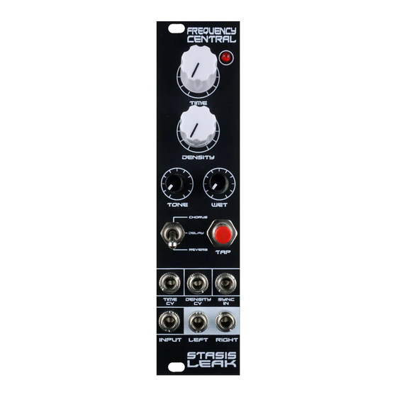
Stasis Leak is a 48kHz DSP effects module, providing a choice of stereo chorus, stereo plate reverb
and tap tempo delay. Stasis Leak is based around a Belton ABE-FX sub board, which in turn is based
around a Coolaudio V1000 chip.
What's not included on this build doc: How to wire the whole thing together within an enclosure.
Maybe you know this bit already. Some hints on page 4.
Bypass LED resistor
Stasis Leak features 2 PCBs:
•
Main PCB (schematic)
•
Belton
ABE-FX, a fully populated SMD PCB which plugs into the Pots 'n' sockets PCB
Please observe correct polarity of the electrolytic caps and ICs!
Build documentation for:
Stasis Leak
Chorus/tap delay/plate reverb
Tap LED resistor
Advertisement
Table of Contents

Subscribe to Our Youtube Channel
Related Manuals for Frequency Central Stasis Leak


Summary of Contents for Frequency Central Stasis Leak
- Page 1 Stasis Leak is a 48kHz DSP effects module, providing a choice of stereo chorus, stereo plate reverb and tap tempo delay. Stasis Leak is based around a Belton ABE-FX sub board, which in turn is based around a Coolaudio V1000 chip.
- Page 2 Bill of Materials 33R x 1 470pF x 4 Belton ABE-FX B100K x 4 100R x 1 100nF x 1 You can buy this from Pin Header 1K x 1 10uF x 3 me, or some other SPDT toggle x 1 3K9 x 4 47uF x 2 place.
- Page 3 Main PCB: Populate the Main PCB front first, as shown on the silkscreen, starting with the lowest profile components, so: • Resistors, diode • IC sockets • Header for Belton. You will need to space this off the board by 1mm or so. Wedge a credit card between it and the PCB, then solder it in place.
- Page 4 Building your Stasis Leak into an enclosure The Stasis Leak PCB is designed to fit into a 1590BB enclosure. The Bypass LED needs to have it’s pad on the PCB grounded, as part of your 3PDT wiring. Please note that there are centre holes for the potentiometers on the PCB, you can use these to mark your enclosure.
Need help?
Do you have a question about the Stasis Leak and is the answer not in the manual?
Questions and answers