CoolLED pE-800 User Manual
8-channel led illumination
Hide thumbs
Also See for pE-800:
- Quick start manual (9 pages) ,
- Setup manual (8 pages) ,
- Quick start manual (4 pages)
Table of Contents
Advertisement
Quick Links
Advertisement
Table of Contents

Related Manuals for CoolLED pE-800


Summary of Contents for CoolLED pE-800
- Page 1 User Manual pE-800 8-channel LED illumination DOC-058 Iss 3...
-
Page 2: Table Of Contents
Introduction ..................... 3 Safety Precautions ................... 3 Getting Started – System Components ............ 6 Installation and Setup ................7 pE-800 LEDs overview ................10 Control Overview ................... 11 LightBridge – Standard/TTL mode ............15 LightBridge – Analogue Mode ..............18 LightBridge –... -
Page 3: Introduction
This manual should give you all the information required to install and operate your new light source. Additional information can be found on our website at www.coolled.com. Safety Precautions While LEDs are a much safer illumination system than the mercury and metal halide lamps that they replace in microscopy applications, precautions should still be taken with this product. - Page 4 2.4. Disconnecting the mains supply is achieved by unplugging the power cord from the power supply block or the Light Source. Only plug in the power cable, once the Light Source is attached to the microscope. 2.5. There are no serviceable parts within the Light Source. Removing any of the screws and covers will result in the safety of the Light Source being impaired.
- Page 5 2.9. EMC compliance This product is tested to the requirements of standard IEC/EN 61326-1 concerning electromagnetic compatibility. This is a Class A product. In a domestic environment this product may cause radio interference in which case the user may be required to take adequate measures. DOC-058 Iss 3...
-
Page 6: Getting Started - System Components
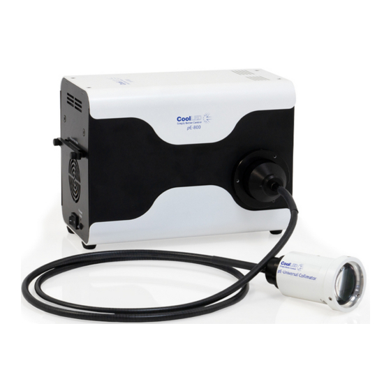
Getting Started – System Components The CoolLED pE-800 Light Source is supplied with the following components: • Main Light Source with Optical Output for 3 mm liquid light guide. • DC Power Supply type GST160A12-R7B. • IEC Power Cable. •... -
Page 7: Installation And Setup
Installation and Setup 4.1. Carefully unpack the components from the shipping material. 4.2. Insert the power connector from the DC power supply as shown, with the flat of the connector body facing up. At this stage do not connect the mains power lead to the DC power supply. - Page 8 4.5. Connect the second end of the liquid light guide into the desired microscope using the required coupling mechanism. If using the pE-Universal Collimator, refer to the dedicated User Manual for correct installation (www.coolled.com/products/accessories/pe-universal-collimator/). DOC-058 Iss 3...
- Page 9 Connect the mains lead supplied to a convenient socket, plug the IEC connector into the DC power supply and switch the power on at the mains. The pE-800 can now be switched on using the rocker switch shown in the below image.
-
Page 10: Pe-800 Leds Overview
LEDs overview 5.1. The pE-800 is an eight-channel Illumination System, with each of the eight channels covering a distinct spectral region to suit use with common fluorophores and their relevant filter sets, from DAPI in the UV to Cy7 in the near infra-red. -
Page 11: Control Overview
LightBridge. The LightBridge software can be downloaded either from the User Guide (USB stick) that is provided with the pE-800 or from the CoolLED website (www.coolled.com/support/imaging-software/). Details of the operation of the LightBridge can be found in the relevant section of this User Manual. - Page 12 (www.coolled.com/support/imaging-software/). 6.4. The pE-800 can be controlled directly by TTL signals to control the ON/OFF state of the Light Source. To define the LED irradiance or to set a sequence, the TTL signals will need to be applied in combination with communication from the LightBridge application.
- Page 13 The details of the physical TTL connections for the pE-800 are shown below. TTL Port 15 Position D-Sub, High Density Receptacle, Female Sockets Connector Pin # Name Type Maximum Rate Input/Output Voltages 635 nm Digital Input 0 ≤ V ≤ 5.5 V...
- Page 14 6.5. Analogue The irradiance of the LEDs in the pE-800 can be set by applying an Analogue Voltage to the relevant connections. A signal of 0-10 V can be applied to the Analogue inputs and relates to 0-100 % irradiance. For example, a 6.5 V signal applied to an input will set the channel to 65 % irradiance.
-
Page 15: Lightbridge - Standard/Ttl Mode
LightBridge – Standard/TTL mode 7.1. When the CoolLED LightBridge is opened the below display will be shown (if the pE-800 is not switched on). The status will be shown in the bottom right corner as Offline. 7.2. Once the power switch of the Light Source is turned on and the System is connected to the PC with a USB cable, the LightBridge will detect the presence of the Light Source and show the status as “Online”. - Page 16 7.3. The irradiance of each of the eight channels can be adjusted by either clicking and moving the slider with your mouse, typing the irradiance figure in the text box or adjusting the irradiance using the arrows. 7.4. Checking the box below the irradiance figure will put that channel into a selected state.
- Page 17 7.5. Pressing the On/Off button in the bottom left corner of the display will cause all wavelengths in the selected state to illuminate at their defined irradiance. DOC-058 Iss 3...
-
Page 18: Lightbridge - Analogue Mode
LightBridge – Analogue Mode Checking the Analogue mode box removes the ability to control the On/Off status and the channel irradiance through the LightBridge. The pE-800 irradiance level will now be controllable from a voltage between 0-10 V to the relevant Analogue input pin. The On/Off state of the Light Source will be controllable with a TTL signal. -
Page 19: Lightbridge - Sequence Runner Mode
LightBridge – Sequence Runner Mode 9.1. To access Sequence Runner Mode click on the dropdown tab at the top of the page that is labelled “Standard/TTL” under normal operating conditions. Select “Sequence” from the dropdown list. 9.2. Once “Sequence Runner Mode” is selected the following display will be shown. - Page 20 9.3. Define the triggering order by checking the boxes of the required channels in the order you would like them to illuminate. The first box checked will select the first channel of a triggering sequence, the second box will select the second channel and so on.
- Page 21 9.5. “Sequence is running” will be displayed to show that the sequence is active. The pE-800 will now trigger the defined channels in the order selected with every TTL high signal to the “Global TTL” input. channel channel channel channel...
- Page 22 9.6. To stop the sequence, click the “Stop” button. 9.7. If you wish to change the defined triggering order, press the “Clear” button. DOC-058 Iss 3...
-
Page 23: Lightbridge - Demo Mode
All the checkboxes will now be reset and list “0” next to all channels. LightBridge – Demo Mode 10.1. The CoolLED LightBridge includes a Demo mode, which allows some of the features and a level of automation to be demonstrated without the need for additional hardware or software. - Page 24 10.3. Once “Demo Mode” is selected the following display will be shown. All channels will be set to the off state at 0 % irradiance. 10.4. Set the required channel irradiance levels by adjusting the relevant slider, typing in the text box or using the arrows. Define the selected channels by clicking in the designated check box.
- Page 25 10.5. Select whether you would like the light output to be a pulse or to ramp up by checking the box for one of these fields. 10.6. Define the pulsing interval or ramp duration by typing in the text box or using the arrows.
- Page 26 10.7. To start the demonstration sequence, press the “OFF” button to change the state to “ON”. 10.8. Whilst the sequence is running the selected channels, order of triggering and interval cannot be adjusted. To stop the sequence, press the “ON” button to change the state to “OFF”. DOC-058 Iss 3...
- Page 27 10.9. To change the channels that will be triggered or adjust the order, the clear button will need to be pressed. 10.10. All channels will have their sequence order returned to “0”. The other settings will remain. DOC-058 Iss 3...
-
Page 28: Lightbridge - Additional Settings
11.1. Power Up Configurator The Power Up Configurator allows you to determine the mode of operation, channel intensities and selected state that the pE-800 will default to when powered up connected to the LightBridge. 11.1.1. The Power Up Configurator can be accessed from the “Tools” drop-down menu at the top of the page. - Page 29 Channel selected state 11.1.4. Alternatively, the pE-800 can be set to initialise in “Analogue Mode” by selecting the “Analogue enable” option from the dropdown menu. The channel selection and irradiance levels will be unavailable, as these will be defined by the Analogue signals applied to the pE-800.
- Page 30 11.1.5. For the chosen settings to be selected upon power-up, the “Irradiance level set, LEDs on” or “Irradiance level set, LEDs off” option needs to be selected from the dropdown menu. 11.1.6. To confirm the settings, press the “Save & Exit” button. Alternatively, if you do not wish to confirm the settings press the “Exit”...
- Page 31 11.2. System information Information about the pE-800 can be accessed using the LightBridge. 11.2.1. To access the system information, please select the ‘About’ option from the ‘File’ dropdown menu. 11.2.2. The following window will be displayed. The ‘Software version’ refers to the version of LightBridge that is being operated.
- Page 32 11.3. LightBridge display settings 11.3.1. The LightBridge application window can be increased or decreased in size by using the ‘+’ or ‘-‘ buttons at the top of the window. 11.3.2. To ensure that the Lightbridge application is always accessible when using multiple applications, it is possible to set the LightBridge to always appear in front of other windows.
- Page 33 11.4. Saving and loading settings 11.4.1. It is possible to save the current settings in the LightBridge to be recalled later. With the desired settings in place, select the “Save as” option from the “File” dropdown menu. 11.4.2. A window similar to the below example shall be displayed. Choose the location to save, name the file and press the “Save”...
- Page 34 11.4.3. The saved settings will be confirmed at the bottom of the LightBridge window. 11.4.4. To load previously saved settings, select the “Load mode from file” option from the “File” dropdown menu. DOC-058 Iss 3...
- Page 35 11.4.5. Select the desired preset file from your saved location and press the “Open” button. 11.4.6. The loaded settings will be shown on the LightBridge window. DOC-058 Iss 3...
- Page 36 Pressing the “Exit – pE-800 LED’s shut down” option will close the LightBridge and change the state of the Light Source to OFF. Pressing the “Exit – pE-800 LED’s on with last settings” option will close the LightBridge but maintain the current state of all channels. This may be required if continuing to control the Light Source externally (for example via TTL).
-
Page 37: Fitting Excitation Filters
Fitting Excitation Filters 12.1. An Excitation Filter Holder is provided with all pE-800 Systems as standard. This will arrive installed into the Light Source. 12.2. The Excitation Filter Holder can be removed from the pE-800 by loosening the two thumbscrews. - Page 38 365 nm (This side faces LED Light sources) An example of the label fitted to an Excitation Filter Holder for an SB variant pE-800. 12.4. The Excitation Filter Holder has been designed so that it is only possible to fit into the Light Source in one orientation.
- Page 39 To ensure the optimal performance of installed excitation filters, it is important that these are fitted in the correct orientation. The arrow in the below image shows the direction of light through the pE-800. Most excitation filters have a directional arrow on the side. Excitation filters should be installed in the holder with this arrow pointing down (as shown in the image below).
- Page 40 12.6. The excitation filters are secured into the holder with a single grubscrew per filter. A suitable hex key will be provided with the pE-800. Grubscrew locations 12.7. The Excitation Filter Holder should be fully inserted into its channel and secured in position using the two thumbscrews.
-
Page 41: Software Updates
Occasionally it may be necessary to upgrade the firmware of the Light Source. This can be carried out in the field by following the steps below. Please contact support@coolled.com for the necessary firmware file. 13.2. To upgrade the Light Source firmware using the LightBridge, the System needs to be put into Firmware update mode. - Page 42 13.4. When the LightBridge is opened the window below will be shown. Click on the box labelled “…” and select the required firmware file from the saved location on your PC. 13.5. Once the file has been selected, the file path length will populate the “File” box.
- Page 43 13.6. Once the firmware programming has been completed a message will display “Programming complete”. Pressing the “Exit” button will return you to the default workbench page. 13.7. The Light Source shall remain in Firmware Update mode, as indicated at the bottom of the LightBridge window, until the power is cycled using the rocker switch.
-
Page 44: Additional Information
Grounding pin For particularly sensitive applications, such as Electrophysiology, it may be desirable ground the pE-800 to avoid any electrical interference. The pE-800 has a designated location to allow for a grounding pin to be attached. This is located on the right-hand side of the Light Source and has an internal M3 thread for connection. -
Page 45: Product Specifications
-weight 0.58 kg 15.4. Environmental Conditions The pE-800 is designed for indoor use only. Operating Altitude: ≤ 3,000 m asl Working Temperature: 5 ~ 35 °C Working Humidity: 20 % ~ 90 % RH non-condensing Storage Temp. & Humidity: -40 ~ +85°C, 10 ~ 95 % RH... -
Page 46: Warranty And Repairs
Light Sources. You can help us by filling in our online contact form and providing us with your contact details and the serial number of the CoolLED Light Source that you wish to return, and we will collect it free of charge. -
Page 47: Contact Details
Contact Details 19.1. Headquarters Address CoolLED Ltd 26 Focus Way Andover Hants SP10 5NY 19.2. Telephone Worldwide - +44 (0)1264 323040 USA & Canada - 1-800-877-0128 19.3. Worldwide - +44 (0)1264 723897 19.4. Email General - info@coolled.com 19.5. Website www.coolled.com... - Page 48 Appendix 1 Installing your CoolLED system on Windows machines 20.1. Windows 10 When you first plug your CoolLED system into your PC with the USB cable, Windows will automatically install the driver files. 20.2. Windows 8 and earlier The first time your CoolLED Illumination System is connected to your PC via...
- Page 49 20.2.3. The window shown below will be displayed. Select the ‘Browse my computer for driver software’ option. DOC-058 Iss 3...
- Page 50 20.2.4. Select the ‘Let me pick from a list of device drivers on my computer’. DOC-058 Iss 3...
- Page 51 20.2.5. Select ‘Port (COM & LPT)’ and then click the ‘Next’ button. DOC-058 Iss 3...
- Page 52 20.2.6. Select the ‘(Standard port types)’ from the ‘Manufacturer’ field, select ‘Communications Port’ from the ‘Model’ field and press the ‘Have Disk…’ button. 20.2.7. Press the ‘Browse…’ button on the ‘Install From Disk’ window. DOC-058 Iss 3...
- Page 53 Locate the CoolLED pE Driver file and press the ‘Open’ button. The ‘Copy manufacturer’s files from:’ field will now be populated with the server location of the pE-Driver. Press ‘OK’ to confirm this. DOC-058 Iss 3...
- Page 54 20.2.8. Select ‘CoolLED USB Virtual Serial Port A’ in the ‘Model’ field and press ‘Next’. 20.2.9. A warning window will be displayed. Press the ‘Yes’ button to confirm. DOC-058 Iss 3...
- Page 55 ‘Always trust software from “CoolLED Ltd”’ and press the ‘Install’ button. 20.2.11. A window will be displayed confirming that the driver software has been updated. Press the ‘Close’ button. The pE-800 will now be ready to use via USB. DOC-058 Iss 3...
- Page 56 With the pE-800 now recognised by Windows, the specific Virtual COM port that has been assigned can be found in ‘Device Manager’ by expanding the ‘Ports (COM & LPT)’ field. The pE-800 will be listed as ‘CoolLED USB Virtual Serial Port A’.
Need help?
Do you have a question about the pE-800 and is the answer not in the manual?
Questions and answers