Table of Contents
Advertisement
Quick Links
Advertisement
Table of Contents

Related Manuals for Foxtech T30s


Summary of Contents for Foxtech T30s
- Page 1 Hand-held GCS T30s User manual V 1.2.3 video&data module V20 V30 2020.08...
-
Page 2: Table Of Contents
3.2. Item list (V30: 15km grade)..........- 7 - 4. Product Instruction ................ - 8 - 4.1. T30S main components name ..........- 8 - 4.2. V20 Airborne Unit Indicator&Interface Instruction ..- 9 - 4.3. V20 Receiver Installation and Connection ...... - 10 - 4.4. - Page 3 10.3. V20 Video&Data Transmission Module Parameters ..- 50 - 10.4. V30 Video&Data Transmission Module Parameters ..- 51 - 10.5. T30s Remote Controller Port Instruction ..... - 51 - 11. Firmware Upgrading Procedure ..........- 54 - 11.1. HID Controller ..............- 54 - 11.2.
-
Page 4: Disclaimer
2. Product Precautions 1) T30s, the ground terminal (hereinafter referred to as ground unit) is used with the airborne unit (hereinafter referred to as airborne unit). 2) T30s has different versions based on the different data link. -
Page 5: Installation Note
It takes about 5-6hs to be fully charged. 3. Product Introduction T30s is a hand-held ground control station that integrates remote control, data transmission and ground station. T30s is highly integrated, small size, easy operation, multichannel adjustable, dual S-BUS outputs and so on. - Page 6 It can be widely used in the field of control and data transmission for industrial drones. 3.1. Item List (V20: 5km grade ) T30s remote controller ×1 V20 receiver x 1 TNC 2.3G ZYJB antenna×2 SMA 2.3GZYJB antenna×2...
- Page 7 3.2. Item list (V30: 10km grade) T30s remote controller×1 V30 receiver x 1 TNC 1430-1444MHz ZYJB antenna×2 SMA 1430-1444MHz ZYJB antenna×1 Accessories 1、power plug XT30 power cable * 1 Charger×1 Wire Power for remote controller 2、SBUS, TTL signal wire GH 3pin * 3...
-
Page 8: Product Instruction
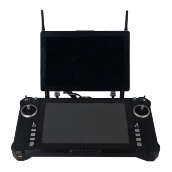
4. Product Instruction 4.1. T30S main components name ①T30S secondary display: Used for extended display of host video ②Left and right rockers: corresponding T1, T2, T3 and T4, used for flight control ③Four three-position switches: corresponding SA, SB, SD, SE... -
Page 9: V20 Airborne Unit Indicator&Interface Instruction
④Left and right rotary knobs: corresponding LD and RD ⑤Two buttons(or three-position switches): corresponding S1, S2 (or SC, SF) ⑥9 key channels: corresponding F1~F9 ⑦Power button and indicator: used for power on and power off the device ⑧Power, signal strength, transmitting and receiving indicator: used for indicating power, working status ⑨Left and right deflector rods: corresponding T5 and T6(return to center mode) ⑩RF antenna interfaces*2: used for connecting RF antennas... -
Page 10: V20 Receiver Installation And Connection
③Date transmitting indicator: light will flicker in the condition of data transmitting. ④Signal strength indicator: S3 ON, signal is weak; S3 and S2 ON, signal is moderate; S3, S2 and S1 ON, signal is strong. ⑤Key switch: used for firmware upgrading, out-of-control protection settings, restore the default transmission settings. - Page 11 3. As shown in the above photo, connecting TTL port/ S-Bus port of the V20 receiver to your device by lead wire of servo. SBUS interface TTL interface Receiver Flight controller or Receiver Flight controller other device or other device 4.With 7.4-12v DC power input, S1-S3 indicators will flicker.
-
Page 12: V30 Airborne Unit Indicator&Interface Instruction
4.4. V30 Airborne Unit Indicator&Interface Instruction Front View ①Video transmission CPU indicator: light will be continuously ON in normal working condition. ②Data transmitting indicator: light will be continuously ON after successful connection of airborne unit and ground unit. ③Signal strength indicator: S3 ON, signal is weak; S3 and S2 ON, signal is moderate; S3, S2 and S1 ON, signal is strong. -
Page 13: V30 Receiver Installation And Connection
⑤HDMI video input interface: connecting camera ⑥USB port: used for firmware upgrading and parameters setting ⑦CVBS video input interface: used for analog video input. By default, the S-BUS1 and S-BUS2 interfaces output the CH1 to CH16 of the remote control to 1-16 channels. 4.5. -
Page 14: T30S Second Display Instruction
1-16 channels. 5. T30S Second Display Instruction 1. Before powering on the T30S, connect the HDMI and USB ports of the main display to the HDMI and Type-c ports of the secondary screen respectively. 2. After successful connection of the Type-c port to the secondary screen, the split- screen and touch function can be realized, but if you plug in the 5V port, the touch function of the secondary screen cannot be enabled. -
Page 15: Split-Screen Setting
4. In the ‘Display Options’ of the tablet PC settings, select ‘1. move the tablet display’ and ‘2. LONTIUM to do calibration. Once calibrated, it can be used normally. 5.2. Split-Screen Setting The factory setting of the screen display is split up and down. If the user is not used to it, right mouse click on the desktop and select "Display Settings"... - Page 16 When T30s is switched on and off, please pay attention to the power button, power indicator, and 4pcs power capacity indicators (25%,50%,75%,100%) and 5pcs data link indicators(RS1, RS2, RS3, TX, RX) 1. Press and hold the power button, the power indicator light will be on, then release the button according to the speed of action to decide whether the computer is on.
-
Page 17: Remote Controller & Receiver Indicator Instruction
6.2. Remote Controller & Receiver Indicator Instruction 6.2.1. Remote Controller Indicator Instruction V20: the module with data Indicator Status Define flicker transmitting Receiving and V30: working indicator transmitting V20: the module without data indicator TX transmitting V30: no communication V20: the module with data flicker receiving Receiving and... -
Page 18: V20 Receiver Indicator Instruction
25%、50%、75%, 100% Full capacity 100% 4 lights flicker and the High temperature protection buzzer with continuous condition short sound Indicator light shows normal, buzzer with Remote controller idle alarm continuous short sound 6.2.2. V20 Receiver Indicator Instruction flicker No video signal input Indicator Status Define... -
Page 19: Remote Controller Antenna
RS2, RS3 6.3. Remote Controller Antenna The T30s is available in several versions such as the R20 version, V20 video&data link version, and no communications version. Different version, the type and frequency of the two antennas A1 (right) and A2 (left) mounted on the remote control are different. -
Page 20: Channel Monitoring And Calibration
7.2. Channel monitoring and calibration The above diagram shows the channel monitoring interface, showing the status of each channel of the remote control. When your remote control is not centered properly or there is rudder shake. Triple click on the upper left corner of the red box to bring up the remote control calibration function options, to calibrate each analog channel. -
Page 21: Channel Configuration
neutral, then click to finish calibration. The RD, LD knob will make a dripping sound once when the switch is in the neutral position. The channel display of the remote control is divided into three parts. The left part shows the output value of SBUS-1, the middle part shows the corresponding status of each channel, and the right part shows the output value of SBUS-2. - Page 22 middle position, the adjustment range is from -125 to 125, and the linear servo stroke amount -31 to 31. The steering stroke can be adjusted from -150 to 150. The default is -100 to 100. Do not adjust if there is no special need. 3.
- Page 23 Write data: Click once to write a new configuration data Load configuration: call different storage profiles Save configuration: save the current configuration as a configuration file for easy finding Restore default: restore all parameters of the current page to default values After each configuration change, click <write data button>...
-
Page 24: Fail-Safe Setting
Right Turn left Turn right The default control mode of T30s is the American mode. This manual uses the American mode as an example to illustrate how the remote control is operated. 7.4. Fail-safe Setting 1. Fail-safe setting, click the small white box of the channel you need to open fail-safe, when there is √... -
Page 25: Channel Hold
▲Fail-safe data is output by the R20 receiver only when there is no signal connection. ▲After each successful configuration, it can be verified by the flight control, ground station or servo. ▲If the R20 is powered down or the SBUS signal cable is disconnected during verification, the fail-safe data will not be received by the third-party device. -
Page 26: Throttle Hold
7.6. Throttle Hold 1. Select throttle control switch 2. Select the gear position where the control switch trigger remains. ‘0’ represents low gear, ‘1’ represents middle gear and ‘2’ represents high gear. Three gears can be used separately. 3. Enter throttle retention value. 4. -
Page 27: Alarm Instructions For Remote Control
9. Restore Factory Setting. T30s is with powerful function, so there are many parameters that can be set. We can restore the factory settings of T30s with one key. Step as below: ①Enter the restoring factory setting interface and click it, and the system will pop up a warning prompt to confirm the option again. -
Page 28: Charge The Remote Controller
T30s with built-in 10200mAH lithium battery, the data link module will work normally with 1W power; T30s can work about 3.5h with the full battery capacity. If the battery indicator shows low power, please stop the flight and charge the T30s in time. -
Page 29: V20 Video&Data Link Serial Port Operation
User name: admin Default Parameters of the video&data link module Password: ADMIN LAN port IP: 192.168.168.11 (receiver); 192.168.168.12 (remote control) Serial port baud rate: 115200, 8N1 8.2. V20 Video&Data link Serial Port Operation Default baud rate of the serial port is 115200, pls refer to the following steps to connect the flight control, ground station software. - Page 30 ④ Open the browser and put the IP address (airborne end: 192.168.168.11; Ground end: 192.168.12) to the address bar. ⑤Then enter user name and password. User name: admin; Password: ADMIN; - 30 -...
-
Page 31: V20 Lan Port
V20 and LAN camera by Lan-to-4pin cable, set the IP address, video can be transmitted. 1. The default IP address of T30S and V20 is set to the same network segment before leaving the factory. Airborne end: 192.168.168.11 Ground end: 192.168.168.12. - Page 32 2. Before connecting the LAN port of the airborne unit to the camera or other network devices, please make sure the IP address of the device is in the same network segment as the airborne terminal. 3. First time you use the camera, please make sure the IP address is in 192.168.168.XXX network segment.
-
Page 33: Fast Reset And Configuration Of Video Transmission Module
8.4. Fast Reset and Configuration of Video Transmission Module If your video transmission device becomes unresponsive during use, you need to restore to factory settings. The airborne end needs to be configured to master mode and the ground end needs to be configured in slave mode. Pls refer to the below steps: 8.4.1. - Page 34 2)The computer must set its network Settings (TCP/IP properties) to automatically obtain the IP address (refer to baud rate modification of serial port ). 3)Open the browser, in the address bar input IP: 192.168.168.1 4)Pls log in. User name: admin; Password: admin; The first log after the reset, you will be asked to change the password.
- Page 35 7)After log in, pls select wireless->RF, pls refer to the below parameters to do configuration and then click submit. (choose the frequency and transmission power based on your requirement) Note!Channel Bandwidth, Channel Frequency, Network ID of the airborne end and ground terminal need to be configured the same.
- Page 36 9) Choose Serial->USB0, this port is used to configure serial port parameters. Baud rate can be adjusted according to the own requirement. Click submit when the write is complete. - 36 -...
-
Page 37: Fast Configuration Of Video Transmission Module Of
10)Choose Admin->Logout, click Logout Now. 8.4.3. Fast Configuration of Video Transmission Module of 1) Enter the parameter configuration interface (refer to airborne end, the only difference is that the input IP address is 192.168.168.2). 2) After log in, pls choose Network->LAN->Edit. 3) Configure the parameters as shown in the figure below, and click submit after the configuration is completed. - Page 38 communication can be established. 5) Click Serial->Settings, choose Data. After parameters configuration, click submit. The baud rate of port must be set 115200. It cannot be modified, otherwise the communication will be affected. 6) Choose Serial->USB0, this port is used for parameters configuration of serial port.
-
Page 39: V30 Video&Data Transmission Module Operation
For LAN version, cannot enter to set the IP address, after connecting with the camera, in the T30S computer network settings (TCP/IP properties) set to the same IP network segment with the camera and then video can be obtained. -
Page 40: Video Connection Instruction For Hdmi Version
1. After powering on the airborne unit, connect it to the camera, CPU indicator is always on when video is input normally. 2. The LAN port of the internal module of the T30S remote control has been connected to the network port. After the signal connection is normal, check the computer, and set its network setting (TCP/IPV4 attribute) to ‘192.168.168.xxx’... -
Page 41: Video Connection Instruction For Lan Version
9.2. Video Connection Instruction for LAN Version 1. Connect the V30 and network camera by the standard 4-pin to Ethernet cable, then connect the 7-12V power supply, the LAN port of the internal module of T30S remote control has been connected to the Ethernet port. - Page 42 The above figure takes the network camera IP address of 192.168.168.20 as an example. 3. As shown above, computer network settings (TCP / IPV4 properties) address set to 192.168.168.15 (must be in the same network segment with the network camera). After finishing the setting, click on the confirmation.
-
Page 43: Display The Video In Mission Planner
5. Enter the address of your network camera rtsp://192.168.168.20:554/user=admin&password=&channel=1&stream=0.sdp? 6. The other characters are filled in according to the camera's settings parameters, the corresponding camera is usually equipped with software or set, such as the following examples rtsp://192.168.168.20:554/user=admin&password=&channel=1&stream=0.sd 192.168.168.20 This is the IP address of the connected device :554 This is the port number of the RTSP service, which can be changed in the device's network service. - Page 44 3.Click GetGstreamer source 4.Enter the following address (Note size set and half symbols) rtspsrc location=rtsp://192.168.168.13/stream0 latency=0 ! decodebin ! videoconvert ! video/x-raw,format=BGRA ! appsink name=outsink 5.Download the relevant software package for the first time and wait for the download to complete. And restart the software. 6.After finishing steps 1-4, you will get the camera video source.
-
Page 45: Display Image In Qgc
7.Right - click to zoom in on the ground 9.4. Display image in QGC First, verify the video stream is available in video software such as VLC and then open MISSIONPLANER; 1. Currently, GQC does not support H.265 encoding, it is needed to input in the browser IP:192.168.168.13 to log in V30 Transmitter. -
Page 46: V30 Parameters Setting
2. Change the video encoding mode to H.264 3. Open QGC software, Click general and find video. VIDEO source chooses RTSP VIDEO STREAM in RTSP URL: input RTSP: / / 192.168.168.13 / stream0 10. V30 Parameters Setting 10.1. Connecting the device 1. - Page 47 About 3s after the device is powered on, the CPU light flashes, indicating the successful device initialization. 3. Enter serial port configuration mode The T30 is matched with COM6 and the V30 is matched with the port number of the tool. In the computer, by using serial port tool, set the baud rate as 115200bps, data bit as 8, stop bit as 1, no check bit, no flow control.
- Page 48 10.2. Command Configuration List Low power 15DBM Type Command Value Instruction Moderate power 20DBM AT^SPWR= High power 25ddm Setting RF power 9600 Baud rate 9600 14400 Baud rate 14400 19200 Baud rate 19200 38400 Baud rate 38400 AT^SBR= 56000 Baud rate 56000 Setting serial 57600 Baud rate 57600...
- Page 49 Center node(main mode) AT^SMOD= Slave node(secondary Setting main and mode) secondary mode Type=0 cancel fixed frequency mode Type=1 set fixed frequency AT^SFIX=type,Fre mode Setting fixed Freq 8060-8259,14279- frequency mode 14478,24015- 24814,17850-18050 If you want to query the current configuration value of the device, input the following command to query.
-
Page 50: V20 Video&Data Transmission Module Parameters
5.Exit the serial port configuration mode Enter three characters "ATE" in the serial tool. Wait for the device to return "Exit Config Mode!", indicating successful exit from serial port configuration mode. 10.3. V20 Video&Data Transmission Module Parameters 2.304 - 2.390GHz Can be modified in the V20(5Km grade video and data link) 2.402 - 2.482GHz... -
Page 51: V30 Video&Data Transmission Module Parameters
XT30 10.5. T30s Remote Controller Port Instruction The T30s computer is with 6 COM ports. Among these COM ports, COM5 and COM6 are only for internal use. COM5 is the special port for the debugging software, and COM6 is the serial port for the remote controller data transmission. - Page 52 The corresponding relationship between interface and port is as follows: 4-wire Correspondin 4-wire sequence pin1-3.3V,pin 2-GND,pin 3-TXD,pin 4-RXD COM1 interface g port 5-(From top to bottom) pin1-3.3V,pin 2-GND,pin 3-TXD,pin 4-RXD RS232 COM2 pin1-3.3V,pin 2-GND,pin 3-A,pin 4-B RS485 COM3 pin1-3.3V,pin 2-GND,pin 3-Z,pin 4-Y RS422 COM3 pin1-TX1+,pin 2-TX1+,pin 3-TX2-,pin 4-TX2-...
- Page 53 3.Select to enter the Advanced interface and select Super IO Configuration. 4.Select Serial Port 3 Configuration。 5.Select 422 MODE, press F4 to save, press ENTER to confirm and restart. - 53 -...
-
Page 54: Firmware Upgrading Procedure
In order to meet more customer needs, we have integrated all the channels into the HID device gamepad in T30s. If you don't find HID device gamepad in your remote control, don't be confused, you may be using an older hardware version of T20 or T21, which doesn't support HID function. - Page 55 3.If the device named "chinowing HZY-JOY" is in the device list, it means your remote control has HID gamepad function. If it doesn't, it doesn't support. 4. Right mouse button, select Game Controller Settings. - 55 -...
- Page 56 5.Select "chinowing hzy-joy" and click on the Properties. You can see each channel in the test bar. Operate the rocker and the corresponding channel state will change accordingly. The X-axis/Y-axis, z-axis, x-rotation, y-rotation, z-rotation, dial-up and slider are analog channels. The visual helmet is mapping one of the rockers, the button is mapping the three-gear switch, button and other digital channels.
-
Page 57: T30S Remote Controller Firmware Upgrading
11.2. T30S Remote Controller Firmware Upgrading 1.Click on the official website to download the firmware, select the appropriate version of the firmware and save it locally. 2.Set all three switches (SA, SB, SD and SE) of the remote control to the mid-range position to ensure that all buttons are in the release state. -
Page 58: V20 Receiver Firmware Upgrading
6.Wait for firmware upgrade until a dialog box pops up indicating the completion of firmware upgrade. Close the firmware upgrade tool. 11.3. V20 Receiver Firmware Upgrading 1. Visit the official website to download the firmware, select the appropriate firmware version and save the firmware locally. 2. -
Page 59: Common Questions
Please check that the ID of each set must be different and the channel must be set differently to avoid interference of the same frequency. 5.The parameters setting software shows <Remote control port not found> Verify that the remote-control port number is correct. - 59 - 13. T30S Remote Controller Parameters... - Page 60 Control range V20: 5km grade V30: 15km grade RF transmitting power V20: 0.1w-1w adjustable V30: 0.1w-0.5w adjustable Remote control latency 30ms Battery capacity 12V/12000mAh or external battery can be connected Operating hours 4.5hs with full capacity Overall weight 3200g Display screen 10.1 inch+ industrial touch screen +800cd/sunlight readable Definition...
Need help?
Do you have a question about the T30s and is the answer not in the manual?
Questions and answers