Table of Contents
Advertisement
Quick Links
Advertisement
Table of Contents

Related Manuals for Duratool D03125


Summary of Contents for Duratool D03125
- Page 1 MODEL: D03125 3½ DIGITAL MULTIMETER...
- Page 2 IMPORTANT SAFETY INFORMATION Please read these instructions carefully before use and retain for future reference. Important safety information. Read the instructions carefully. High voltage. Danger. Ground. Double Insulation (Class II safety equipment). Fuse must be replaced as per the specification herein. 200mA/250V •...
- Page 3 MAINTENANCE • Before moving the rear cover, disconnect the probe from the circuit to be measured. • To protect the internal circuit, replace the fuse with one of the same specification: F1 250mA/250V F2 10A/250V • Do not use the instrument until the rear cover is put back in place and the screws have been tightened.
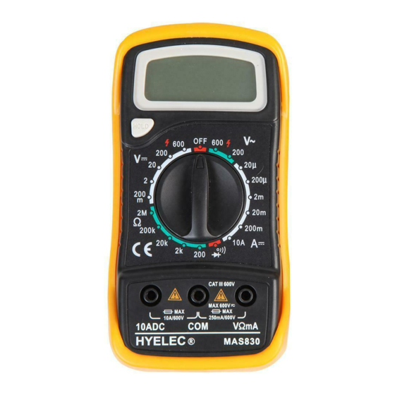
- Page 4 Display • 3½ digital, 15mm height, 7 sections LCD display. Backlight • Press the BACKLIGHT button to turn on the backlights, which will last for five seconds. To turn it on again, press the button when required. Function and Range Switch •...
- Page 5 10mV ±0.5% of reading, ±3 digits 200V 100mV ±0.5% of reading, ±3 digits 600V ±0.8% of reading, ±5 digits • Overload protection: 200mV range: 250V DC or RMS; • The rest ranges: 600V DC or RMS. Direct Current Measurement Range Resolution Accuracy 20μA...
- Page 6 Diode and Circuit On-Off Measurement Range Description When the on-resistance is smaller than (70±30) Ω, the built-in buzzer will sound. Displays the approximate diode postive voltage. • Overload protection: 250V DC or RMS. AC. Temperature Measurement Range Resolution Measurement Accuracy -20°C to 0°C ±10% Range, ±2 digits °C...
- Page 7 Direct Current Measurement • Place the black probe into the COM jack. For current, not exceeding 200mA, to be measured, put the red one into the “VΩmA” jack. For current to be measured between 200mA and 10A, insert the red probe into the 10A jack.
- Page 8 pole of the diode being measured and the black one to the negative pole. Read the approximate forward voltage drop of the diode on the display. Circuit On-Off Measurement Insert the black probe into the COM jack and the red one into the V.Ω.mA •...
Need help?
Do you have a question about the D03125 and is the answer not in the manual?
Questions and answers