Ruckus Wireless ZoneDirector 5000 Getting Started Manual
Hide thumbs
Also See for ZoneDirector 5000:
- User manual (467 pages) ,
- Configuration manual (30 pages) ,
- User manual (322 pages)

Related Manuals for Ruckus Wireless ZoneDirector 5000


Summary of Contents for Ruckus Wireless ZoneDirector 5000
- Page 1 Ruckus Wireless ZoneDirector 5000 Getting Started Guide Part Number 800-70310-001 Rev F Published June 2013 www.ruckuswireless.com...
-
Page 2: Before You Begin
This Getting Started Guide describes the necessary equipment and environment for setting up a ZoneDirector 5000, the physical features and general layout of the device, and instructions for accessing the user interface for the first time. This guide is written for those responsible for installing and managing network equipment. -
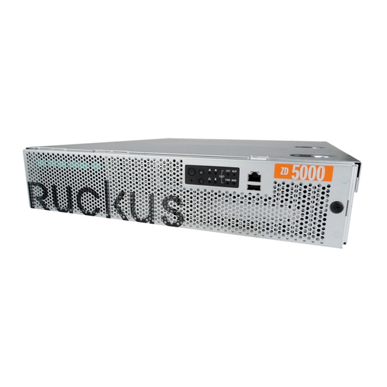
Page 3: Physical Features
Physical Features Front Panel Front panel features Number Description Control panel (see detailed description below) RJ45 serial port (COM2 / serial B) USB port (not used) Front bezel lock Front Panel (bezel removed) Front panel features (bezel removed) Number Description ESD ground strap attachment Hard drive bays (not used) Control panel (buttons and status indicators) -
Page 4: Control Panel
Control Panel Control panel buttons and indicators Number Description Power button System reset button System status LED Fan status LED Critical alarm (not used) MJR alarm LED (not used) NMI pin hole button (factory reset button) Chassis ID button NIC1/NIC2 activity LED HDD activity LED (not used) PWR alarm LED (not used) Minor alarm (Amber: system unavailable;... -
Page 5: Rear Panel
Rear Panel 9 10 11 Note: Power supply location is for AC or DC power. AC power supply is pictured. Rear panel features Number Description Cable connector (not used) Two low-profile PCIe add-in cards (not used) Three full-length PCIe add-in cards (not used) Power supply 2 (backup AC power) Power supply 1 (primary AC power) RJ45 serial port (COM2/serial B) - Page 6 Server Rack Installation ZoneDirector 5000 is a 2U form factor server designed for mounting in a standard EIA 19” server rack. The enclosed mounting hardware supports mounting on racks 22.5” to 32.5” deep. For racks of depth less than 22.5”, use rack mount kit TMLCMOUNT21 (available at Avnet, manufactured by Kontron).
-
Page 7: Outer Parts
Figure 1: Rail assemblies and rail screws Step 1: Separate the Slide Rails into the Inner and Outer Parts Extend the inner rail (see 1 in Figure 2) until it locks. Press down the spring safety lock (see 2 in Figure 2) to release the inner rail. Remove the inner rail from the rail assembly (see 3 in Figure 2). - Page 8 Step 2: Install the Outer Rail Slides to the Rack Posts NOTE: The two rail assemblies that are included are NOT interchangeable. Each assembly needs to be installed into the rack by its orientation (right or left) when standing in front of the rack. The right rail assembly is identified with a BLUE sticker and the left rail assembly is identified with a GREEN sticker.
- Page 9 Step 4: Install the Inner Rails on the Server Install the inner rails onto the hex head shoulder screws, and then slide the inner rails forward. Figure 5: Installing the inner rails Step 5: Fasten the Inner Rails to the Server Secure the inner rails with one #6-32 x 1/4 screw for each rail.
- Page 10 Use the rack screws (#8-32 x 3/4) to secure the chassis and rack handles into the rack. See 3 in Figure 8. Figure 8: Securing the server to the rack Congratulations! You have completed mounting the ZoneDirector 5000 into your server rack. page 10 of 18...
-
Page 11: Using Ac Power
Connect the other end of the power cable(s) to an electrical outlet. Connect one end of an Ethernet cable to one of the RJ45 GbE ports on the rear panel of the ZoneDirector 5000, and connect the other end to an Ethernet port on your Admin PC. -
Page 12: Using Dc Power
PSU handle. To insert the PSU, slide the entire unit (green locking tab toward the top) fully into the ZoneDirector 5000 chassis until it locks in place. If using DC power, connect 48V DC input power to the PSU. The DC input polarity is marked on the DC PSU case. - Page 13 DC Power Supply Input Voltage and Current Requirements DC Input Voltage Nominal -48Vdc Minimum -38Vdc Rated -48Vdc to -60Vdc Maximum -75Vdc DC Input Current Maximum 13A @ -38Vdc Grounding the rack installation: To avoid the potential for an electrical shock hazard, for AC power you must include a third wire safety ground conductor with the rack installation.
- Page 14 Use the following IP address (if it’s not already active) and make the Select following entries: • IP Address : 192.168.0.22 ( or any address in the 192.168.0.x network other than 192.168.0.2, in use by the ZoneDirector 5000 ) • Subnet mask : 255.255.255.0 • Default gateway : 192.168.0.2...
-
Page 15: Web Interface
Accessing the ZoneDirector 5000 There are two ways to access the ZoneDirector 5000: • Web Interface (GUI) : Access the Web interface using an Internet browser to connect to ZoneDirector’s static IP address. • Command Line Interface (CLI) : Access the CLI using a terminal program (such as PuTTy or Hyperterminal) connected to ZoneDirector via the RJ45 Serial port on the front panel. -
Page 16: Appendix A: Psu Replacement
Appendix A: PSU Replacement The ZoneDirector 5000 includes two redundant, hot-swappable power supply units (2 AC PSUs or 2 DC PSUs). No chassis components need to be removed to add or replace a PSU. To remove and replace a PSU: Identify the faulty PSU by looking at the PSU status LED (red indicates PSU failure, green indicates normal operation). -
Page 17: Appendix B: Fan Replacement
ESD ground strap attachment on the front panel of the chassis. Open the front chassis cover of the ZoneDirector 5000. It may be necessary to extend the ZoneDirector into a maintenance position. Identify the faulty fan. Each fan has a “service required” LED that lights Amber when the fan is malfunctioning. -
Page 18: Federal Communications Commission Notices
Connect the equipment to an outlet other than the receiver’s • Consult a dealer or an experienced radio/TV technician for assistance Changes or modifications to this equipment that have not been approved by Ruckus Wireless may void the user’s authority to operate this equipment. Industry Canada Statement This device complies with Industry Canada ICES-003 rules.
Need help?
Do you have a question about the ZoneDirector 5000 and is the answer not in the manual?
Questions and answers