
Related Manuals for Vivotek AM-520


Summary of Contents for Vivotek AM-520
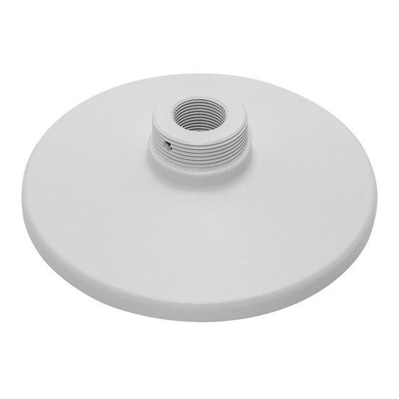
- Page 1 VIVOTEK Fixed Dome & PTZ Series Mounting Cap Installation Guide Using AM-520 mounting cap and compatible accessories Rev. 1.5 IP Sur veillance...
- Page 2 FE8172V / FE8171V / FE8174/ FE8174V / FE8181 / FE8181V / FE9181-H / FE9182-H / FE9381-EHV / FE9382-EHV / FE9191 / FE9391-EV / FE9582-EHNV You may also refer to VIVOTEK's website for the list of supported models. Support for other models can be available through time.
-
Page 3: Installation
Installation Mounting Hole Definitions Above are the locations of different groups of mounting holes for matching different cameras: Hole Applicable Cameras Screw No. of Screw Type screws pack FD8361 / FD8361L / FD8362 /FD8362E / FD8363 M5X10 round / FD8335H/ FD8372 head FD8162 / FD8135H / FD8163 / FE8181 / M4X12 round... - Page 4 For cabling and configuration details with each network camera, please refer to their documentation. Refer to the table below for the description of the included screws: Screw Description No. of Material char. screws M5X10 (A) M4X12 (B) M3X6 (C/E/F/K) M3X8 (D/L/J) M3X6 (H) M3X8 (I) Hex wrench and hex...
- Page 5 Configuration - Pendant Pipe AM-118 AM-116 AM-520 180 mm AM-118 AM-117 AM-520 180 mm AM-118 AM-522 3/4" Female adapter 3/4" pendent pipe AM-520 180 mm Note: The 3/4" female adapter is separately purchased.
- Page 6 Configuration - Wall Mount AM-212 HEX SOCKET SCREW AM-520...
- Page 7 Configuration - Gooseneck AM-221 AM-520 HEX SOCKET SCREW NOTE: When installing the mounting cap, take note that the orientation of the mounting cap can affect the camera's shooting direction. You may need to remove the mounting cap, rotate, and re-install it for the best orientation. Use the hex wrench to tighten its retention hex...
- Page 8 Installing Camera to Mounting Cap Refer to the matching table on page 4 for the mounting hole information for your camera. 1. You should route cables through other accessories before you install cameras to the mounting cap. 2. Route power lines and other cables through the mounting cap. 3.
- Page 9 Note that for cameras that come with cable glands, e.g., FD8134 and FD8134V, it can be tricky passing them through a 3/4" pendant pipe. From local network 1. You can pass the cable gland and other wires into or through the pendant pipe, while leaving the RJ-45 connector behind.
- Page 10 You can then connect the RJ-45 from the camera with that from the local network using an RJ-45 coupler. When done, press the coupler and the cables into the recess of the bracket. RJ-45 coupler Align and install the camera to the bracket.
- Page 11 FD8134V M3X6 Screws C holes FD8135H M4X12 Screws B holes...
- Page 12 FD8362E A HOLES...
- Page 13 MD8562 M3X6 Screws E holes Press and route cables through here...
- Page 14 FE8172V / FE8174V / FE9381-EHV For details routing and preparing for waterproof cabling, please refer to the camera's Quick Installation Guide. M3X8 Screws D holes FD8164 / FD8137H F holes...
- Page 15 FD8361L M5X10 A holes Route cables through here...
- Page 16 FD8361 1. Secure 2 of the mounting screws (those that are away from the routing hole). Do not completely tighten the screws yet. Refer to the previous page for mounting hole positions. 2. Pass cable assembly through the adapter and the 3/4" pipe. M5X10 5 ~ 10 cm 3.
- Page 17 FE8172 / FE8173 / FE8174 / FE9181-H / FE9191 I holes FD8164V / FD8137HV K holes...
- Page 18 FE8181 / FE8181V / FE9182-H / FE9382-EHV / FE9391-EV / FE9582- EHNV B holes B holes...
- Page 19 FD8167 / FD8167-V / FD8138-H J holes...
- Page 20 FD8367-V / FD8367-TV / FD8338-HV L holes...
Need help?
Do you have a question about the AM-520 and is the answer not in the manual?
Questions and answers