Advertisement
Table of Contents
- 1 Table of Contents
- 2 Features
- 3 Front Panel Diagram
- 4 Rear Panel Diagram
- 5 System Design & Operation Considerations
- 6 System Design Examples
- 7 Diagram 4 Multi Room Installation
- 8 Diagram 5 Multi Zone Installation #1
- 9 Diagram 6 Multi Zone Installation #2
- 10 Diagram 7 Home Theater/Multi Room Installation
- 11 Installation Considerations
- 12 Installation
- 13 Operation
- 14 Troubleshooting
- 15 Speci Cations
- Download this manual
Advertisement
Table of Contents

Related Manuals for Pyle PT8000CH


Summary of Contents for Pyle PT8000CH
- Page 1 PT8000CH 8-Channel Home Theater Amplifier Multi-Zone Audio Source Control, Rack Mount Amp, 8000 Watt...
-
Page 2: Table Of Contents
Keep this manual for future reference. The PT8000CH contains the excellent performance and reliability that PYLEUSA products have been recognized for. The PT8000CH features the exibility needed for demanding custom installation applications. It is ideal for use in home theater, stereo, multi-room, multi-zone and commercial applications. -
Page 3: Features
FEATURES Audiophile Design Sophisticated design and superior internal components result in outstanding sound quality, performance and long term reliability. Advanced Protection Each channel is individually protected. If the circuitry determines that a channel must be shutdown for protection, a rare occurrence, only the channel a ected will be turned o . -
Page 4: Front Panel Diagram
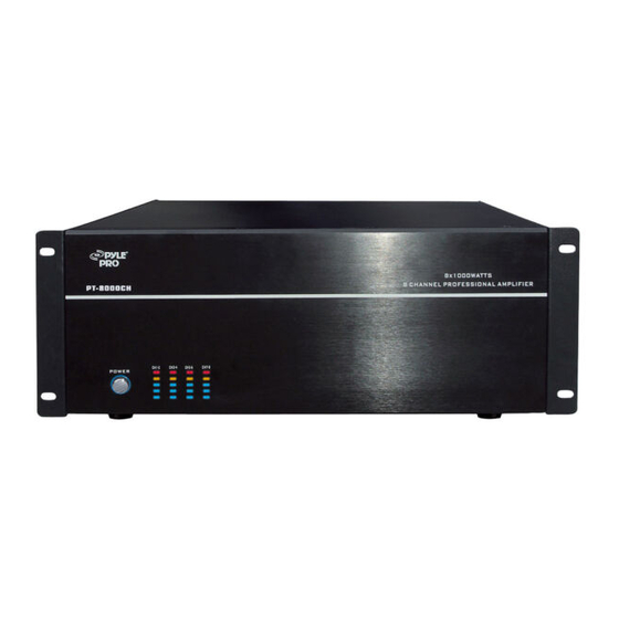
DIAGRAM 1 FRONT PANEL 1. POWER SWITCH Master power switch. Turns o power to ampli er and Power Mode Circuitry. 2. POWER OUTPUT LEVEL INDICATOR This is level meter which shows outputs levels of ch 1-2 ch 3-4 ch 5-6 & ch 7-8 condition on the operation. - Page 5 1-2. Main bus inputs allow outputs from receivers, CD players, TVs, or any stereo audio sources to be ampli ed across all channels for easy multi-room applications. Auxiliary inputs allows an addition audio source to be played on any channel that is switched to AUX . 3-4.
-
Page 6: System Design & Operation Considerations
A distinct unit of the ampli er that provides output to one speaker. On the PT8000CH the input to each channel can be con gured to select from the BUS INPUT, the AUX INPUT or that channel’s unique CHANNEL INPUT. Two adjacent channels can be bridged to provide higher power to one speaker. - Page 7 BUS* AUX* LINE Switch Allows each channel to play a variety of di erent inputs. Depending on the switch position the channel ampli es the signal connected to the BUS input, the AUX input, or its own LINE input. R R + L L Switch When either a BUS or AUX input is selected, this switch is used to direct the channel to play the left signal from the input “L”...
-
Page 8: System Design Examples
Power Input Jack Output Jack SYSTEM DESIGN EXAMPLES There are many ways to con gure the PT8000CH ampli er. The following pages contain some typical installation examples. Use these examples to generate ideas for your system design. Multi-Room Installation Example (Diagram 4) This illustrates the simplest use of the PT8000CH, distributing audio throughout the home. -
Page 9: Diagram 4 Multi Room Installation
Home Theater / Multi-Room Example (Diagram 7) This con guration allows the user to access the sources connected to a home theater receiver for use in a multi-room installation. It relies on the home theater receiver having a multi-room or similar output. The Input Selection switch on each channel is set to “BUS”... -
Page 10: Diagram 5 Multi Zone Installation #1
DIAGRAM 5 MULTI ZONE INSTALLATION #1 www.PyleUSA.com... -
Page 11: Diagram 6 Multi Zone Installation #2
DIAGRAM 6 MULTI ZONE INSTALLATION #2 www.PyleUSA.com... -
Page 12: Diagram 7 Home Theater/Multi Room Installation
DIAGRAM 7 HOME THEATER/MULTI ROOM INSTALLATION www.PyleUSA.com... -
Page 13: Installation Considerations
INSTALLATION CONSIDERATIONS • Place the amplifier with the feet resting on a solid flat level surface. • Place the amplifier in a well-vented area to provide proper cooling. In areas that lack proper ventilation, such as tight cabinets or racks, it may be necessary to install small fans to create air movement. -
Page 14: Installation
INSTALLATION CAUTION: All connections and switching must be done with the ampli er’s master power switch positioned to “o ”. Select the Power Mode Selection Refer to the Power Mode Selection area under installation considerations to determine which setting to use to turn the ampli er on. Once you have determined which mode you will be using set the switches as outlined in the following chart: SELECTION MODE... - Page 15 Selecting Inputs (See Diagrams 8 & 9) Each channel is capable of delivering the source from many inputs. The three main inputs are BUS, AUX and LINE IN. The selection for these inputs is done via the Input Selection switch, marked “BUS-AUX-LINE”. To select a source for each channel, follow the steps below: 1.
- Page 16 The speaker must be connected to the terminals immediately under the “BRIDGED” text as indicated in Diagram 10. All input selection and settings for the bridged channels will be done on the channel to the left. Do not connect more than one speaker to the outputs of the bridged channel. To “ON”...
- Page 17 Using Standard Connections (See Diagram 11) For best performance use high quality speaker cables. The banana plug outputs on the back of the ampli er allow for a variety of ways to connect your speakers to the ampli er. Diagram 11: Binding Post Detail Turn to tighten Insert Banana Plug Insert speaker wire or spade connector...
-
Page 18: Operation
OPERATION See Diagram 1 for the location of the following: Power Switch The switch marked “Power” on the front panel of the ampli er will turn o all ampli er circuitry no matter which turn on mode is selected. Refer to the “Power Mode Selection” section for further information. Active LED When lit, the Active LED indicates that the ampli er is operating. -
Page 19: Troubleshooting
TROUBLESHOOTING The ampli er is designed to function trouble-free. Most problems occur because of operating errors. If you have a problem please check the troubleshooting list rst. If the problem persists, contact your authorized dealer. PROBLEM POSSIBLE CAUSES AND SOLUTIONS Audio cable to the source component is not No sound is heard on all connected properly or the cable is bad. - Page 20 PROBLEM POSSIBLE CAUSES AND SOLUTIONS Audio cable to the source component is not No sound is heard on all connected properly or the cable is bad. Use another channels cable that you know is good. The Input Selection switch is positioned incorrectly. Refer to installation instructions for proper settings.
-
Page 21: Speci Cations
FEATURES: • Multi-Zone Audio Source Ampli er System • High-Powered & Distortion-Free Audio Distribution • 8-Channel Sound Processing Amp Design • Integrated 4-Channel Bridgeable (Bridge) Switches • Front Panel Color LED Graphic Audio Level Display • Independent Channel Rotary Level Control Knobs •... - Page 22 Questions? Issues? We are here to help! Phone: (1) 718-535-1800 Email: support@pyleusa.com...
Need help?
Do you have a question about the PT8000CH and is the answer not in the manual?
Questions and answers