Acom 1000 User Manual
Hf+6m, linear amplifier
Hide thumbs
Also See for 1000:
- Instruction manual (24 pages) ,
- User manual (52 pages) ,
- Installation (3 pages)

Related Manuals for Acom 1000


Summary of Contents for Acom 1000
- Page 1 OU T S TANDING HF P OWER PRODUC T S ACOM 1000 HF + 6m Linear Amplifier User's Manual Installation, Operation and Maintenance August 2020...
- Page 2 User's Manual | ACOM 1000 | HF + 6m Linear Amplifier This manual is for electronic distribution mainly. If you have it on paper and you no longer need it, please, recycle it! The latest versions of our User's Manuals are available at www.acom-bg.com...
-
Page 3: About Documentation
ACOM products and services. Further, this User's Manual is provided AS IS and ACOM shall not be liable for possible errors contained herein. - Page 4 User's Manual | ACOM 1000 | HF + 6m Linear Amplifier Title of Documentation ACOM 1000 HF + 6m Linear Amplifier User's Manual Installation, Operation and Maintenance Type of Documentation User's Manual Purpose of Documentation This manual explains Installation, Operation and Maintenance of the ACOM 1000 HF + 6m Linear Amplifier.
-
Page 5: Table Of Contents
User's Manual | ACOM 1000 | HF + 6m Linear Amplifier Contents ABOUT DOCUMENTATION ..........................3 GENERAL INFORMATION ........................... 7 1.1. Introduction and Description ......................7 1.2. Owner Assistance ..........................7 1.3. Equipment Supplied ........................7 1.4. Features ............................8 1.5. - Page 6 User's Manual | ACOM 1000 | HF + 6m Linear Amplifier SPECIFICATIONS ............................32 7.1. Parameters ............................ 32 7.2. Functions ............................33 7.3. Storage and Shipment ........................34 Figures Figure 2-1 Connections ........................... 13 Figure 3-1 ACOM 1000 Display and Control ....................16 Figure 3-2 Information Screens and Control Functions Structure ..............
-
Page 7: General Information
Congratulations on purchasing one of the finest HF amplifiers in the world today. ACOM is pleased that you have chosen one of our products, and we will endeavor to provide you with the information and support you need to enjoy your purchase for many years. -
Page 8: Features
Easy maintenance. Signatures of the amplifier internal status are stored in a nonvolatile memory for 7 most recent auto protection trips. This information can be forwarded to your dealer for diagnostics. Using an EXCEL APPLICATION (available from ACOM or your dealer free of charge) and a PC you can decode the signatures by yourself, too. -
Page 9: Safety Considerations, Explicit Definitions
1.5. Safety Considerations, Explicit Definitions The ACOM 1000 HF + 6 meters Linear Amplifier is a Safety Class I unit. The third grounding lead of its mains cord (which is colored yellow with two green stripes) and the ground stud on the rear panel of the amplifier (marked GND) must be connected to the station's grounding system for safe operation. - Page 10 User's Manual | ACOM 1000 | HF + 6m Linear Amplifier PRECAUTIONS: D A N G E R ! H I G H V O L T A G E ! The amplifier works with high voltages up to 3000V, which are LETHAL! For your safety, pull the amplifier power plug out of the mains wall outlet and WAIT AT LEAST 30 minutes EACH TIME BEFORE you remove the cover of the amplifier.
-
Page 11: Installation
N O T E Before you install your amplifier, thoroughly read this manual. First, carefully inspect the cardboard carton and its contents for physical damage. ACOM ships amplifiers in highly protected containers, but it cannot assure that mistreatment by shippers will not occur. -
Page 12: Amplifier Location Selection
User's Manual | ACOM 1000 | HF + 6m Linear Amplifier 2.3. Amplifier Location Selection N O T E The weight of the unit is about 22kg, which should preferably be handled by two persons. Position the amplifier near the place where it will be used. You will need an easy access to the command knobs and indicator's area, as well as to the rear panel cabling. -
Page 13: Figure 2-1 Connections
User's Manual | ACOM 1000 | HF + 6m Linear Amplifier Figure 2-1 Connections First, connect the ground stud of the amplifier (on the rear panel, marked GND) to the station’s grounding system (see Figure 2-1 Connections Connect a coaxial cable with a PL-259 plug from the transceiver output to the amplifier rear panel RF INPUT socket. - Page 14 User's Manual | ACOM 1000 | HF + 6m Linear Amplifier N O T E Your amplifier will not work if KEY-IN is not connected properly. Transceiver producers give different names to this output and they are for instance TX- GND, SEND, T/R-LINE, etc.
-
Page 15: Installation Of External Fan
User's Manual | ACOM 1000 | HF + 6m Linear Amplifier It is preferable that you use the wall outlet closest to the source. The installation leads should be at least 1.5mm² (AWG 15 or SWG 17). Check if the respective fuses can handle current up to 10A as well, and whether the voltage corresponds to the voltage for which the amplifier is set (see Section 2.2 Line Voltage... -
Page 16: Power On, Controls And Indicators
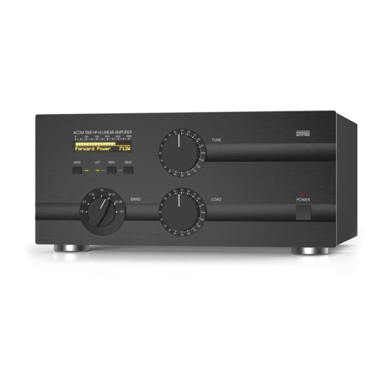
"LINE" on the rear panel (see ). The LED indicator above the red ON/OFF button Figure 2-1 Connections located on the front panel must light red and "ACOM 1000" will appear on the OLED (see Figure 3-1 ACOM 1000 Display and Control Figure 3-1 ACOM 1000 Display and Control You'll note that the upper line of the OLED always reads the peak forward power, even in STBY mode. -
Page 17: Figure 3-2 Information Screens And Control Functions Structure
User's Manual | ACOM 1000 | HF + 6m Linear Amplifier In this position (called OFF LINE hereafter) only the micro-controller is operational, while the amplifier itself is still turned off (the tube is not powered at all). The control of the amplifier is accessible during OFF LINE and ON LINE states, each having several... -
Page 18: Operation
User's Manual | ACOM 1000 | HF + 6m Linear Amplifier 4. OPERATION Operation of the amplifier is simplified due to the TRI tuning aid, Auto-Operate function, and automatic protection system, so you'll be able to begin using the amplifier immediately after the installation. -
Page 19: Changing Operate And Standby Modes
User's Manual | ACOM 1000 | HF + 6m Linear Amplifier After the indicated period expires, the ON/OFF button stops flashing and lights green constantly. If the auto-operate function is selected to ON (see Section ), the green 5.2 Auto-Operate enabling and disabling OPER LED lights too. - Page 20 User's Manual | ACOM 1000 | HF + 6m Linear Amplifier The amplifier can operate safely as long as the REFLECTED POWER is LESS THAN 300W. Also, impedance matching is assured for loads presenting a VSWR of up to 3:1. Although for some loads and bands, matching is possible at even higher VSWR levels, the drive power must be reduced to prevent the REFLECTED POWER from exceeding 300W.
-
Page 21: Table 4-1 Approximate Tuning Preset
User's Manual | ACOM 1000 | HF + 6m Linear Amplifier We recommend that you tune-up at the center frequencies of the preferred frequency band. First select the band switch (never with RF applied!). Then use (see ) in order to... -
Page 22: Table 4-2 Using Tri Tuning Aid
User's Manual | ACOM 1000 | HF + 6m Linear Amplifier Tuning Procedure While a continuous (CW) signal at the desired frequency is still applied: Look at the upper scale (forward power). Obtain maximum power using the upper (TUNE) •... -
Page 23: On Line Information Screens And Control Functions
User's Manual | ACOM 1000 | HF + 6m Linear Amplifier Tuning to the left of the center would lead to the opposite: less gain and more power attainable. Of course, this requires more drive power, more plate current, and more plate heat, which shortens tube's-expected life, as its cathode would be faster exhausted. -
Page 24: Auto-Protection System
User's Manual | ACOM 1000 | HF + 6m Linear Amplifier 4.5. Auto-Protection System When any abnormal condition is detected, the amplifier will evaluate the risk and may use three different degrees of protection, depending on the nature of the problem. Each event is accompanied by a text telling you the reason. -
Page 25: Off Line Operation
User's Manual | ACOM 1000 | HF + 6m Linear Amplifier 5. OFF LINE OPERATION There is a control function and 14 information screens available in this state of the amplifier. You can enable/disable the Auto-Operate feature. You can also list the auto - protection signatures. The tube is not powered at all (only the micro-controller is active) during these operations. -
Page 26: Reading Auto-Protection Signatures
User's Manual | ACOM 1000 | HF + 6m Linear Amplifier 5.3. Reading Auto-protection Signatures On every Hard Fault protection trip of the amplifier, signature information is stored in its nonvolatile memory. The 7 most recent auto-protection trip signatures related to the amplifier internal status are stored there, which you can copy and forward to your dealer for diagnostics. -
Page 27: Maintenance
User's Manual | ACOM 1000 | HF + 6m Linear Amplifier 6. MAINTENANCE 6.1. Cleaning W A R N I N G Do not use solvents for cleaning - they may be dangerous both for you and for the amplifier paint or plastics. -
Page 28: Acom 1000 Simplified Schematic Diagram
Many software-derived protections are based on this information. N O T E Забележка! Note! Detailed electrical schematic diagrams are available from ACOM or from your dealer on request. Page 28 of 36 | S e c t i o n MAINTENANCE August 2020... -
Page 29: Figure 6-1 Acom 1500 Simplified Schematic Diagram
User's Manual | ACOM 1000 | HF + 6m Linear Amplifier Figure 6-1 ACOM 1500 Simplified Schematic Diagram August 2020 S e c t i o n MAINTENANCE | Page 29 of 36... -
Page 30: Troubleshooting
User's Manual | ACOM 1000 | HF + 6m Linear Amplifier 6.5. Troubleshooting Please, see Section for the method of reading the auto-protection 5.3 Reading Auto-protection Signatures signatures. You can decode them using the information below. The signatures are structured in two lines, three groups by six symbols for every one event of auto- protection. - Page 31 N O T E Additional information is available from ACOM or from your dealer on how to interpret these values. Using an Excel application available from ACOM or your dealer free of charge, and a PC, you can decode these signatures.
-
Page 32: Specifications
User's Manual | ACOM 1000 | HF + 6m Linear Amplifier 7. SPECIFICATIONS 7.1. Parameters Frequency Coverage: All amateur bands 1.8-54MHz, extensions and/or changes on request; Power Output: 1000W PEP or continuous carrier, no mode limit; In continuous carrier modes (RTTY etc.) for transmissions longer than 15 minutes (up to several hours depending on ambient temperature), the external auxiliary fan must be mounted. -
Page 33: Functions
User's Manual | ACOM 1000 | HF + 6m Linear Amplifier 7.2. Functions Antenna Impedance Matching Process: plate-load True Resistance Indicator (TRI) aided; T/R System: QSK operation with built-in, vacuum RF antenna relay (special quiet installation)' Protections: Cover interlock for operator's safety;... -
Page 34: Storage And Shipment
User's Manual | ACOM 1000 | HF + 6m Linear Amplifier 7.3. Storage and Shipment W A R N I N G Should you need to transport the amplifier, use the original packing as described below. First, switch off the amplifier. Pull the mains plug out of the outlet. Disconnect all cables from the rear panel of the amplifier (remove the ground connection the last). - Page 35 User's Manual | ACOM 1000 | HF + 6m Linear Amplifier This manual is for electronic distribution mainly. If you have it on paper and you no longer need it, please, recycle it! The latest versions of our User's Manuals are available at www.acom-bg.com...
- Page 36 о support@acom-bg.com www.acom-bg.com ACOM and the ACOM logo are registered trademarks of ACOM Ltd. in many countries, including the EU and United States. I The used images are illustrative only. Subject to change without notice. I Printed in Bulgaria. All rights reserved. I Design and content by ACOM Ltd. I August 2020.
Need help?
Do you have a question about the 1000 and is the answer not in the manual?
Questions and answers