Acom 1010 Manual
- User manual (40 pages) ,
- Operating manual (20 pages) ,
- Schematic diagrams (15 pages)
Advertisement
GENERAL INFORMATION
ACOM is pleased that you have chosen one of our products, and we will endeavor to provide you with the information and support you need to enjoy your purchase for many years.
We urge you to read all of the following materials before you embark on operating your new amplifier.
Introduction and Description
This manual explains:
- Installation
- Operation and
- Maintenance of the ACOM 1010 HF linear amplifier.
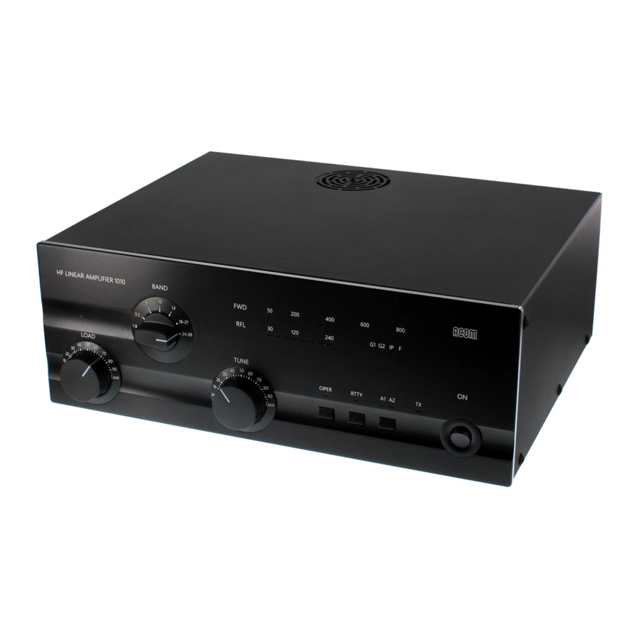
The ACOM 1010 is a self-contained linear amplifier that covers all amateur bands, from 1.8 through 29.7 MHz. It provides over 700 W PEP of output power (or 500 W in continuous-duty operation) with less than 60 W of drive. The amplifier is designed to tolerate SWR levels of up to 3:1 throughout its operating range, and tuning is simplified by ACOM's exclusive True Resistance Indicator (TRI). Also, a built-in antenna selector switch with two outputs is included to provide instant choice of antennas. Importantly, a variety of system parameters are continuously monitored and available to the operator to assure safe and efficient amplifier operation.

Owner Assistance
If assistance is needed, you should contact your local dealer first. If necessary, your dealer will contact ACOM for additional guidance.
If you still have an issue you need to discuss with one of ACOM's specialists, the contact information is as follows:
ACOM Ltd.
E-mail: support@acom-bg.com
Bulgaria | Bozhurishte 2227
Sofia-Bozhurishte Economic Zone | 6 Valeri Petrov Str. GPS coordinates: 42.748616о | 23.209801о
Equipment Supplied
The ACOM 1010 amplifier and this User's Manual are shipped in a cardboard carton.
Features
- Easy to operate
The plate-load True Resistance Indicator (TRI) is an ACOM innovation that provides quick and precise tuning, typically in less than 10 seconds. The AUTO-OPERATE function will return the amplifier to the OPERATE mode automatically after each protection trip, saving time and avoiding manual switching. - No antenna tuner needed
No external antenna tuner is required as long as the antenna SWR is 3:1 or lower. The amplifier will perform the functions of an antenna tuner, enabling you to change antennas faster and use them over wide frequency ranges. - User-friendly and durable
This amplifier is both user-friendly and self-monitoring. It is designed to safely withstand up to 240 W of reflected power, up to 100 milliseconds of drive spikes (RF "tails" after a PTT or KEY release), and even operator tuning errors. It is also capable of operating at more than half its designed output power at only 75% of nominal line (mains) voltage. Because it can tolerate deep voltage drops (down to zero for 10 milliseconds) and 15% line voltage spikes, it is particularly suited for use in portable environments, such as field days and DXpeditions. - LED bar-graph display
The upper LED bar-graph always reads peak forward power (except for the service functions) while the lower LED bar-graph is for the reflected power. LED warning indicators are provided for abnormal conditions of grid 1, grid 2, and plate parameters. - Antenna selection
Two antenna outputs are selectable on the front panel of the amplifier. - Efficient tuning
Antenna matching can be achieved in less than 10 seconds and at a quarter of nominal output power, which produces lower risk of interference to other stations and greater safety to the amplifier components. - Transceiver-independent
The amplifier operates without special signaling from the transceiver. It needs only "ground on TX" and 60 W RF drive power to operate at full output power. - Broadband input matching
Broadband input matching circuitry offers excellent loading characteristics for the driving transceiver, from 1.8 MHz to 30 MHz. - Single tube operation
A single Svetlana 4CX800A (GU74B) high-performance ceramic-metal tetrode with plate dissipation of 800 W (forced air cooling, grid-driven) is used for maximum efficiency. - Permanent monitoring and protection of the plate and grids currents
The Bias Optimizer minimizes heat dissipated by the tube, assuring tube longevity. - High voltage protection
Design of the high-voltage power supply eliminates the danger of turn-on transients affecting sensitive devices connected to the same line (mains) circuit. Moreover, the amplifier can be configured for 8 different nominal line voltages: 100, 110, 120, 200, 210, 220, 230, or 240 VAC, 50 or 60 Hz.
INSTALLATION
Unpacking and Initial Inspection
 Before you install your amplifier, thoroughly read this manual.
First, carefully inspect the cardboard carton and its contents for physical damage. ACOM ships amplifiers in highly protected containers, but it cannot assure that mistreatment by shippers will not occur. If damage is evident, notify your dealer immediately. Delay may void the carrier's warranty.
Keep all packing materials for possible future amplifier shipment (see Section Returning to the Service Provider).
Line Voltage Selection
 NOTICE
To avoid damage, which will not be covered under your warranty, check carefully to be certain that the voltage for which the amplifier is set corresponds to your mains nominal voltage.
Normally, the amplifier is supplied set for a nominal line voltage of 240 V. If your mains voltage is not 240 V, you must contact your dealer for instructions. The only exception to this is if the unit has been custom ordered, in which case the voltage selection will be noted in the Table of Individual Data (see Table 2-1 Amplifier individual data).
Table 2-1 Amplifier individual data:

The amplifier power supply can be configured for 8 different nominal line voltages: 100, 110, 120, 200, 210, 220, 230, or 240 VAC, 50 or 60 Hz.
Amplifier Location Selection

The weight of the unit is about 17 kg, which should preferably be handled by two persons.
Position the amplifier near the place where it will be used. You will need an easy access to the command knobs and indicator's area, as well as to the rear panel cabling.
No magnetic-field sensitive devices (such as microphones) should be located next to the right side of the amplifier because its power transformer is located there. It is advisable to position the amplifier to the right of your transceiver.
No temperature-sensitive devices should be located above the exhaust hot air area. This means that the amplifier should not be located under a shelf or other structure that could impede the free movement of air away from the amplifier.
NOTICE
Do not under any circumstances obstruct the air intake (bottom) and exhaust (top cover) areas of the amplifier. Keep a minimum clearance distance of 50 cm (20 inches) above the exhaust opening.
NOTICE
Do not leave accidental paper, cloth or other lightweight pieces around and under the amplifier. They may be drawn in by the cooling air stream and block the vents. This will lead to overheating and accelerated material aging, not covered by the warranty.
Connections
Please, see Figure 2-1 Rear panel - Connections.

Figure 2-1 Rear panel - Connections
Connection to your station must be accomplished in the order described below, before you apply mains voltage to the amplifier.
Before you connect the amplifier to external grounding, you should advise with a licensed electrician and confirm such kind of connection is allowed by your national and local electrical code, safety rules, and regulations in force. Simultaneous connection to the earth grounding and protective earth may be inadmissible or may fall under special requirements in some countries!

Never use the gas installation for grounding. This can cause an EXPLOSION!
Do not use the steam-heating or water-supply network for grounding! You may expose to dangerous voltage not only yourself but also other people using the same installation.
- GND stud
First, connect the wing-nut grounding stud of the amplifier (on the rear panel, marked GND) to the station's grounding system (see Figure 2-1 Rear panel - Connections, Pos. (a)).
![]()
Note that the grounding system may have to withstand currents over 15 A with insignificant voltage drop on it. Therefore, it may be necessary to improve it considerably, i.e., to become less resistive, with heavier leads and lower-resistive ground path. The grounding leads should be at least 4 mm² (AWG 11 or SWG 13). - RF INPUT socket
Connect a suitable coaxial cable from the transceiver output to the amplifier RF INPUT SO-239 socket (see Figure 2-1 Rear panel - Connections, Pos. (b)), using PL-259 plug.
![warning]() NOTICE
NOTICE
In order to avoid a damage, turn off your transceiver's internal antenna tuner. - ANT1 and ANT2 sockets
![warning]() NOTICE
NOTICE
If this is the first time you will use a power amplifier in your station, pay attention to the coaxial cable type from the amplifier's output to the antenna. It must handle the increased power safely, particularly on the 10-meter band. It is suggested that, at a minimum, RG8X (including RG8MINI, RK50-4-11, RK50-4-13) or, even better, RG213 (including RK50-7-11) coaxial cable be used.
Connect a suitable coaxial cable with a PL-259 plug from the amplifier output ANT1 or ANT2 (see Figure 2-1 Rear panel - Connections, Pos. (c)) to the antenna selector or tuner, or to the antenna for the respective frequency band. - KEY-IN socket
This is the amplifier's input for receive/transmit control from the transceiver.
The transceiver controls the amplifier from receive mode into transmit mode (RX/TX) by grounding of the KEY-IN input.
Run a shielded cable from the "ground on transmit" socket or terminal on your transceiver to the amplifier KEY-IN socket (see Figure 2-1 Rear panel - Connections, Pos. (d)). The KEY-IN socket uses a standard RCA phono plug.
![information]() Voltage on the KEY-IN socket does not exceed 12 V and the current is below 6 mA.
Voltage on the KEY-IN socket does not exceed 12 V and the current is below 6 mA.
![information]() Your amplifier will not work if KEY-IN input is not connected properly.
Your amplifier will not work if KEY-IN input is not connected properly.
Transceiver producers give different names to this output and they are for instance TX-GND, SEND, T/R-LINE, PTT, etc. Some transceivers require that "ground on transmit" is implemented via a software command, or by changing the setting of a switch on the rear panel, or interior of the transceiver. Check your transceiver's manual. - Main fuses
![warning]() NOTICE
NOTICE
Make sure you check whether the main fuses installed in your amplifier (see Figure 2-1 Rear panel - Connections, Pos. (e)) correspond to your local mains nominal voltage and if necessary, replace them as described in Section Fuse Replacement!
![]()
If your amplifier is only fitted with one line (mains) fuse, it is suitable for European Community ONLY. Your dealer will check that your amplifier is correctly fused before it is shipped to you. Customers should check with a qualified electrician if the amplifier is to be used outside the country in which it was purchased. - The IEC 320 Power inlet
Please, see Figure 2-1 Rear panel - Connections, Pos. (f).
Due to the different standards in different countries, the power supply cable and mains plug are supplied and mounted by the dealer. He connects to the mains cord end a standard mains supply plug which meets the Safety Class I unit standard in your country. - Preparation of wall outlet
![]()
Before connecting the amplifier to your mains supply using a licensed electrician, check that the supply is correctly wired, and is adequate for power consumption up to 1200 VA. Make certain that the grounding lead is connected properly and that it has a cross section not less than the cross section of the phase conductor in the wall outlet for the amplifier.
It is preferable that you use the wall outlet closest to the source. The installation leads should be at least 1.0 mm² (AWG 17 or SWG 18) at operating 200-240VAC and 1.5 mm² (AWG 15 or SWG 17) at 100-120VAC (recommended values if there are no stricter requirements by your local standard).
Check that the panel fuse has a free capacity for the additional load from the amplifier as specified in Sections Fuse Replacement and 6.1.i) Mains Power Consumption. If you connect the amplifier to a different mains outlet, be sure that you check it, too.
Make sure the main Power switch (marked "ON", see Figure 3-1 Front panel - Display and Controls) on the front panel is in OFF position (see Figure 2-2 Power rocker switch in OFF or ON position) and insert amplifier's mains plug into the wall outlet prepared for it. The amplifier remains switched off (with the "ON" indicator dark).

Figure 2-2 Power rocker switch in OFF or ON position

POWER ON, CONTROLS AND INDICATORS
NOTICE
Do not turn the amplifier on for at least 2 hours after unpacking it in the room where it will be used. Pay particular attention when you move it from a very cold into a warm place - condensation is likely and this could result in damage to the high voltage circuits. In such a case, wait at least 4 hours. A similar effect can occur after a rapid warming of the operating room (for instance after switching on a powerful heater in a cold shack).
NOTICE
In order to avoid any damage (not covered by the warranty), check carefully to be certain that the voltage for which the amplifier is set corresponds to your mains nominal voltage (see Section Line Voltage Selection and Table 2-1 Amplifier individual data).
After following all instructions in Section INSTALLATION, you may turn on the main power switch (marked "ON") on the front panel (see Figure 3-1 Front panel - Display and Controls and Figure 2-2 Power rocker switch in OFF or ON position). The green LED indicator above the switch will illuminate.

Figure 3-1 Front panel - Display and Controls
You will note that the upper LED bar-graph always reads peak forward power, except for the service functions (see Section Service Functions). The 800 W scale resolution is 50 W. Note also that levels below 50 W may be not detected.
The lower LED bar-graph will indicate reflected power up to 240 W. The scale resolution is 30 W.
The OPER button alternatively switches between the OPERATE and STANDBY modes once the amplifier has completed its 150-second warm-up period (see Section Changing OPERATE and STANDBY Modes). The RTTY button reduces the output power of the amplifier to 500 W (see Section RTTY Mode).
The button labeled A1-A2 (see Section Antenna Change) changes the antenna output to either Antenna 1 or Antenna 2, according to the operator's choice. It is the operator's responsibility to connect suitable antennas to the ANT1 and ANT2 connectors (see Figure 2-1 Rear panel - Connections, Pos. (c)).
The red TX LED illuminates whenever the KEY-IN input is keyed (closed to ground), i.e., when the transceiver goes into the transmit mode (see Section Connections.d) KEY-IN socket).
The BAND knob controls the band switch, and LOAD and TUNE are used to adjust the respective variable air capacitors in the amplifier's output circuit. The settings of these three controls must be changed at each band change as well as when an antenna is changed. The three LED indicators located above the knob LOAD are called the "TRI tuning indicator" and they are used to achieve antenna impedance matching during a re-tune procedure (see Section Tuning).
NOTICE
Do not switch the BAND switch knob while transmitting with the amplifier! Hot switching (while transmitting) will eventually destroy the band switch, not covered by the warranty!
There are three warning yellow LED indicators and one fault red LED indicator located in the bar-graphs area. The following describe the error conditions and the correct responses (except for the service functions - see Section Service Functions):
- G1 - when illuminated, a control-grid overload condition exists. Reduce the drive power for safe operation;
- G2 - when illuminated, a screen-grid overload condition exists. Reduce the drive power and/or refresh the tuning for safe operation (see Section Tuning);
- IP - when illuminated, a plate current overload condition exists. For safe operation reduce the drive power and/or refresh the tuning (see Section Tuning);
- F - when illuminated, the amplifier automatic protection has tripped.
If F is accompanied with one of the G1, G2, or IP condition indicators, the cause of the protection trip will be evident. When F alone is illuminated, check the keying wiring (see Section Connections.d) KEY-IN socket). See Section The Auto-Protection System for details about the auto-protection system.
OPERATION
Operation of the amplifier is simplified due to the TRI (True Resistance Indicator) tuning aid, AUTO-OPERATE function, and Automatic Protection System, so you will be able to begin using the amplifier immediately after the installation.
However, to make full use of amplifier's potential and to fully configure it to your local conditions, we recommend that you thoroughly read the following information.
Turning ON and OFF
In order to turn on the amplifier, press the power switch marked "ON" (see Figure 3-1 Front panel - Display and Controls to ON position (see Figure 2-2 Power rocker switch in OFF or ON position). The LED indicator above the switch will glow green and the audible cooling fan will start.
Following a series of automatic self-tests, the OPER LED will begin to flash green and will continue to do so during the 150-second warm-up period. Throughout this period, the amplifier will remain in the STANDBY mode, and the transceiver may continue to be used.
Also, during this period, the A1-A2 button may be pressed to change antennas, i.e., between the antennas connected to the ANT1 and ANT2 outputs (see Figure 2-1 Rear panel - Connections, Pos. (c)). Switching between the antennas does not affect the warm-up process.
NOTICE
To avoid damage not covered under warranty, do not change the antenna output during a transmission, i.e., never press the A1-A2 button when transmitting.
When you intend to have a short operating break, it is better to leave the amplifier in standby mode instead of turning it off. Tube life is shortened by repeatedly turning on and off the tube heater supply. However, if you unintentionally power-off the amplifier, it is best to switch it on again immediately. When the pause is short (up to one minute) and the cathode is still warm, the warm-up period is shortened significantly, which reduces the waiting time and prolongs the tube's expected life.
After the warm-up period is complete, the OPER LED stops flashing and remains illuminated green.
Changing OPERATE and STANDBY Modes
The OPER button changes between two modes. When the green light above the button is illuminated, the amplifier will remain ready to operate, even automatically returning from STANDBY after a high-drive protection trip. That is, after a protection trip, e.g., from an overdrive event, the amplifier will normally shift to the STBY mode for several seconds, but it will automatically return to the OPER mode after that. This is the AUTO-OPERATE feature. Alternatively, the OPER button may be depressed manually to go to and remain in the STBY mode, such as when you leave the station for a while. The green LED goes off and the AUTOOPERATE function is suppressed temporarily. Pressing the OPER button again restores the AUTO-OPERATE feature.
RTTY Mode
Select the RTTY mode to operate continuous-duty modes such as RTTY, SSTV or other data modes. The LED indicator above the RTTY button illuminates and the amplifier operating parameters are changed to reduce tube dissipation. In the RTTY mode, the amplifier output power is reduced to a maximum of 500 W. There is no need to re-adjust tuning when changing between RTTY and normal modes.
NOTICE
In order to avoid any damage (not covered by the warranty), do not change modes during transmission. That is, do not change to or from RTTY or any other mode when transmitting.
Antenna Change
By pressing the A1-A2 button, the amplifier output is switched between the two corresponding antenna outputs, ANT1 and ANT2. The lights above the button indicate the current antenna selection.
NOTICE
In order to avoid any damage (not covered by the warranty) do not change the antenna during transmission.
Tuning
Tuning is possible only in the OPERATE mode.
- Preliminary information
Tuning the amplifier involves a procedure of matching the impedance of the currently used antenna and transmission line to the amplifier tube's optimum characteristic load resistance. This will ensure maximum plate efficiency and optimum RF gain at nominal output power, with minimal distortion and spurious output.
Note that REFLECTED POWER readings depend on the antenna and transmission line impedances only, and not on amplifier tuning. If the load impedance is not a nominally resistive 50-Ohms, the REFLECTED POWER indicator will always show a reading, no matter what the tuning settings.
Proper tuning is always necessary, however, and will allow you to operate at a high-power level, without distortion or any danger to the amplifier.
Note also that the real OUTPUT POWER presented to the load (the antenna and transmission line) is equal to the difference between the FORWARD and REFLECTED power readings. For instance, with a 2.5:1 SWR, readings of 800 W and 150 W FORWARD POWER and REFLECTED POWER respectively, the real OUTPUT POWER is 650 W. At very high SWR levels, such as when no antenna is connected or a badly mismatched antenna is used, the FORWARD and REFLECTED readings will be almost equal, while the real OUTPUT POWER (the difference between them) will be nearly zero.
The amplifier can operate safely if the following rule is obeyed:
"REFLECTED POWER < 250 W".
Also, impedance matching capability is assured for loads presenting a SWR of up to 3:1. Nevertheless, for some loads and bands, matching is possible at even higher SWR levels, but the drive power must be reduced to prevent the REFLECTED POWER from exceeding 250 W. Failure to comply with these guidelines will cause the protection circuits to trip.
For example, if the antenna SWR were 5:1, the maximum attainable forward power would be 540 W, 240 W of reflected power and real output to the antenna and transmission line of only 300 W. In the event your antenna cannot be adjusted to produce a lower SWR, an external antenna tuner may be deployed.
NOTICE
At elevated SWR levels, high voltages and high currents are distributed along the coaxial cable to the antenna, risking internal arcing and heat generation, and likely damage to the cable and any antenna switches that may be used. It is recommended that SWR levels of more than 3:1 not be permitted with coaxial cable above 14 MHz.
It is highly advisable to re-adjust amplifier tuning when antennas have been changed.
Update tuning periodically, even if you have not changed band or antenna, in particular when a significant change in the environment occurs (snow, ice, newly appeared or removed massive objects, alien wires nearby etc.) that would cause significant changes in the antenna impedance.
If you use more than one antenna per band, it is necessary that you select the proper antenna BEFORE to perform the tuning procedure outlined below.
NOTICE
Do not switch the BAND switch knob while transmitting with the amplifier! Hot switching (while transmitting) will eventually destroy the band switch, not covered by the warranty!
NOTICE
When tuning, never apply continuous drive longer than one minute without pausing for at least one minute to allow the tube to cool.
It is recommended that for initial tuning a free frequency in the middle of the band be selected (make sure the frequency is not being used by others so that you do not make QRM). First, with no transceiver power applied, select the band. Then use Table 4-1 Approximate tuning preset in order to achieve an approximate preset for both TUNE and LOAD capacitor knob settings:
Table 4-1 Approximate tuning preset:
| Band, MHz | Load Knob Dial | Tune Knob Dial |
| 1.800 - 2.000 | 47 - 71 | 54 - 32 |
| 3.500 - 4.000 | 34 - 56 | 51 - 33 |
| 7.000 - 7.300 | 32 - 39 | 36 - 30 |
| 10.100 - 10.150 | 62 - 63 | 50 - 48 |
| 14.000 - 14.350 | 37 - 41 | 38 - 31 |
| 18.068 - 18.168 | 41 - 43 | 50 - 48 |
| 21.000 - 21.450 | 59 - 62 | 16 - 10 |
| 24.890 - 24.990 | 50 - 52 | 49 - 46 |
| 28.000 - 29.700 | 63 - 69 | 23 - 10 |
- Tuning Procedure
- Once the antenna and band have been selected (and the TUNE and LOAD adjustments have been initially set as indicated in Table 4-1 Approximate tuning preset), apply between 10 and 20 W of continuous (key down CW) drive signal.
- Look at the upper LED bar-graph (FORWARD POWER) and adjust the TUNE (right hand) capacitor for maximum FWD indication.
- Watch the three TRI LED indicators above the LOAD (left hand) knob and turn it in the indicated direction to center the green light.
- Increase the drive power to get the desired nominal output; then repeat steps (2) and (3), always peaking output with the TUNE adjustment.
No light on the TRI indicator means that the tuning is too far off. To correct this, turn the LOAD and TUNE knobs around the table-suggested positions until the TRI indicator illuminates.

Figure 4-1 Using TRI tuning aid
The TRI indicator will not illuminate until at least 20 W of forward power (output) is achieved. In the event successful matching cannot be accomplished, check the BAND switch position and antenna selection. Then check the antenna SWR at the same drive frequency.
- Tuning hint
A benefit of TRI is that the knob positions are virtually independent. The plate-load resistance decreases to the right and increases to the left of the TRI center. A centered tuning indication corresponds to the proper LOAD capacitor tuning, which presents an optimum load resistance to the tube.
If the LOAD knob is turned to the left with a centered TRI, there will be more gain, but less linearity. When available drive power is insufficient or when less output but better efficiency is needed, e.g., for RTTY and SSTV, this may be desirable. Tuning to the right of the center would lead to the opposite result, i.e., less gain and more power attainable. Of course, this requires more drive power, more plate current, and more plate heat, which shortens tube's-expected life.
Off-center tuning may also be used to compensate for line (mains) voltage variations in order to maintain tube efficiency. In that case, tune to the left when line (mains) voltage is high, or tune to the right if it is low. However, where there is more than a 10% difference from the nominal line (mains) voltage, the voltage selector inside the amplifier should be changed (see Section Line Voltage Selection).
The Auto-Protection System
When any abnormal amplifier condition is detected, the risk will be evaluated automatically and either of two degrees of protection will be applied by the controller.
Degrees of protection:
- First degree of protection - An illuminated LED warning
These include the yellow LED warnings described in Section POWER ON, CONTROLS AND INDICATORS, i.e., "G1" (grid 1), "G2" (grid 2), and "IP" (plate). Operation may be continued but the amplifier is likely to proceed to the second degree of protection, the trip. - Second degree of protection - A trip to the STANDBY mode
The red "F" (fault) LED illuminates and the amplifier automatically goes to the standby mode for several seconds. Also, the green OPER LED goes off. The amplifier will indicate the reason for the protection trip:- If one of the yellow (G1, G2, IP) warning LEDs is illuminated along with the red "F" LED, a current limit has been exceeded and drive power must be reduced or retuning is necessary (see Section Tuning);
- If the last red LED of the reflected-power bar-graph is illuminated together with the red "F" LED, the reflected-power limit has been exceeded and the drive must be reduced or the antenna SWR must be improved;
- If all three LEDs of the TRI indicator above the LOAD knob are flashing simultaneously together with the red "F" LED, the tuning is not adjusted correctly or the antenna impedance has changed and retuning is required (see Section Tuning).
Fault information normally remains on the display for several seconds while the amplifier is in the standby mode. The auto-operate function will attempt to return the amplifier to the operate mode automatically as described in Section Changing OPERATE and STANDBY Modes. If the protection trips repeatedly, the user must attend to the cause of the trip, which is typically too much drive or antenna mismatch.
NOTICE
If all LEDs in the bar-graph area are flashing simultaneously, you must immediately switch off the amplifier to avoid damage.
MAINTENANCE
Both the mains voltage and the high voltages up to 3000 V inside the amplifier are LETHAL!
For your safety, pull the amplifier power plug out of the mains wall outlet and WAIT AT LEAST 30 minutes EACH TIME BEFORE you remove the cover of the amplifier. Do not touch any part inside while the amplifier is open because some residual voltages may still be present.
If no indicator glows upon switching the amplifier ON, the main fuse(s) may have blown (see Section Fuse Replacement).
Periodic Maintenance
Periodically (but at least once per year) check all connections, contact cleanliness and the tightening of all connectors, in particular the coaxial ones.
Check the integrity of the cables, in particular when they are laid on the floor. Check also if the cables are secured well in the area where they come out of the connector body.
Pay particular attention to the mains plug and the wall outlet (see Sections Connections.f) The IEC 320 Power inlet and Connections.g) Preparation of wall outlet). If you have any doubts consult with a qualified electrician.
Periodically check the SWR of the antennas and if this changes over time. Problems could occur more often in poor weather conditions - rain, snow, strong wind etc.
Cleaning
Do not use any solvents for cleaning. They may be dangerous to you and damage amplifier surfaces, paint and plastic components.
Do not open the amplifier. Cleaning of the amplifier outer surface can be done with a piece of soft cotton cloth lightly moistened with clean water.
Also, clean (as much as possible from the outside, without opening the amplifier) all ventilation apertures on the cover and the chassis, including the ones on the bottom.
Never push or put anything into holes in the case - this will cause electric shock.
Fuse Replacement
If replacement of fuses is necessary, first pull out the amplifier mains plug from the mains outlet and wait for at least 30 minutes!
NOTICE
For replacement, only use standard fuses from the types recommended below.
The two Primary Mains Fuses of the amplifier are located on the rear panel (see ). They are fuses of the "F" type (fast-acting / quick-acting / fast blow / quick blow), European size 5x20 mm, ceramic or glass body cartridge.
The fuses must be rated for a current corresponding to your mains nominal voltage:
- 6.3 A / 250 V for operation from 200-240 VAC;
- 0 А / 250 V for operation from 100-120 VAC.
Suitable fuses are:
- For 200-240 VAC mains nominal voltage, e.g.:
- EATON Bussmann, PN: S-501-6.3-R (ceramic body cartridge);
- Littelfuse, PN: 021706.3 (glass body cartridge).
- For 100-120 VAC mains nominal voltage, e.g.:
- EATON Bussmann, PN: S-501-10-R (ceramic body cartridge);
- Littelfuse, PN: 0217010 (glass body cartridge).
If, after Primary Mains Fuses replacement, the device does not operate normally, we recommend repair, performed only by a trained service technician.
Contact your ACOM dealer for assistance (see Section Owner Assistance).
Besides the primary fuses, on the HV PCB and on the MAINS PCB (inside the amplifier) there are three fuses which are not replaced by the user. They are fuses of the "T" type (time-lag / slow-blow), European size 5x20 mm, ceramic (or glass) body cartridge, as follow:
- 1 x 0.8 A, 250 V (located on MAINS PCB);
- 1 x 2 A, 250 V (located on HV PCB);
- 1 x 5 A, 250 V (located on MAINS PCB).
Suitable fuses are:
- 0.8 A, 250 V, e.g.:
- EATON Bussmann, PN: S505-800-R (ceramic body cartridge);
- Littelfuse, PN: 0218.800 (glass body cartridge);
- 2 A, 250V, e.g.:
- EATON Bussmann, PN: S505-2-R (ceramic body cartridge);
- Littelfuse, PN: 0218002 (glass body cartridge);
- 5 A, 250 V, e.g.:
- EATON Bussmann, PN: S505-5-R (ceramic body cartridge);
- Littelfuse, PN: 0218005 (glass body cartridge).

Do not replace fuses located inside the amplifier.
Blown internal fuses can be a symptom of a more serious problem, which should be resolved beforehand. A fault of this type will not occur under normal operating circumstances.
Replacing internal fuses is a complex and potentially dangerous operation.
For this reason, we recommend this work be carried out only by a trained service technician.
Contact your ACOM dealer for assistance (see Section Owner Assistance).
Unauthorized replacement of inside fuses infringes the warranty conditions!
Besides specific national standards, the principal fuses standard applied worldwide is IEC 60127.
Tube Replacement
A single 4CX800A (GU74B) high-performance ceramic-metal tetrode manufactured by Svetlana is employed in the amplifier.
Tube replacement is a complex and potentially dangerous operation that involves adjustment of the plate idling current and is Life-threatening!
For this reason, we recommend this work be carried out only by a trained service technician.
Contact your ACOM dealer for assistance (see Section Owner Assistance).
Simplified Schematic Diagram
Please, see Figure 5-1 Simplified schematic diagram:

Figure 5-1 Simplified schematic diagram
The 4CX800A (GU74B) Svetlana high performance ceramic-metal tetrode (V1) with plate dissipation of 800 W is grid-driven. The input signal from the RF INPUT jack is passed through a broadband input matching circuit, which consists of components on the INPUT PCB and includes the drive-power swamping resistor Rsw. This circuit tunes out the input capacitance of the tube. The swamping resistor Rsw is a termination load for the matching circuit and can dissipate up to 80W of RF drive power. It also eliminates any tendency toward oscillation by the tube, ensuring excellent RF stability of the amplifier.
The cathode resistor Rc creates DC and RF negative feedback, thus stabilizing gain and equalizing frequency response. The combination Lp1-Rp1 in the plate circuit is a VHF/UHF parasitic suppressor. DC plate voltage is fed through chokes RFC1-RFC2 and the capacitor Cb3 blocks it from the output. The output tank, comprised of LP1, LP2, LL, CP1-CP3, and CL1-CL4, forms a classic Pi-L network and suppresses harmonic frequency emissions. This circuit is switched and tuned by S1A-S1C and the air variable capacitors CP1, 2 and CL1, 2. The output signal is fed through the antenna relays K1 and K2 in the WATTMETER PCB. The WATTMETER PCB also includes a high-pass filter for frequencies below 100 kHz, and it prevents the plate supply from reaching the antenna.
The plate RF voltage is monitored through the capacitor Ca and together with the RF WATTMETER is the main source of information for the control circuit of the amplifier in evaluating tuning quality. The control circuit is based on the ATMEGA-8L micro-controller from Atmel. All voltages are delivered from the line (MAINS) and HV PCBs. The currents of the control grid, screen grid, and the plate, as well as the reflected power and tuning quality, etc. are continuously monitored by the micro-controller. Many software-derived protections are based on this information.
Detailed electrical schematic diagrams are available from ACOM or from your dealer on request.
Service Functions
By pressing the OPER and RTTY buttons simultaneously, the upper LED bar-graph is switched to the SERVICE mode, which is indicated by both red bar-graph lights and the yellow G1 light illuminating. Pressing the OPER and RTTY buttons together again will select additional service measurement functions. Pressing them a final time will return the amplifier to the normal operating mode. These steps are detailed below:
- Press the OPER and RTTY buttons together. The two red lights on the right side of the upper bar-graph will illuminate to confirm that the amplifier is in the service mode. The yellow G1 light will also illuminate. The upper bar-graph should show a grid 1 current reading no higher than 5 mA (5 LEDs illuminated);
- Pressing the OPER and RTTY buttons once again will now illuminate the yellow G2 light. This provides an approximate reading of grid 2 voltage. The scale is 30 V per a LED lighted. The upper bar graph should show a voltage reading within the range of either 270-300 Volts (9-10 LEDs illuminated) for RTTY or 210-330 Volts (7 to 11 LEDs illuminated) for SSB and CW;
- Pressing the OPER and RTTY buttons yet again will illuminate the yellow IP light. This provides an approximate reading of combined plate current and grid 2 current. The reading should be no higher than 500 mA (10 LEDs illuminated) for RTTY or 600 mA (12 LEDs illuminated) for SSB and CW. The scale is 50 mA per a LED lighted;
- Pressing the OPER and RTTY buttons a final time will restore the upper bar-graph to its normal function of indicating peak forward power.
The Auto-Protection System will continue to operate in the SERVICE mode.
In case it is necessary to ship the amplifier, please, see Section Storage and Shipment.
SPECIFICATIONS
Parameters
- Frequency Coverage
- All amateur bands in the 1.8-29.7 MHz frequency range;
- Extensions and/or changes on request;
- Power Output
- 700 W PEP or 500 W continuous carrier;
- Intermodulation Distortion
- Better than 35 dB below rated output;
- Hum and Noise
- Better than 40 dB below rated output;
- Harmonic Output Suppression
- Better than 50 dB below rated output;
- Input and Output Impedance
- Nominal value: 50 Ohm unbalanced, UHF (SO-239) type connectors;
- Input circuit: broadband, SWR less than 1.3:1, 1.8-30 MHz continuously (no tuning, no switching);
- Bypass path: SWR less than 1.1:1, 1.8-30 MHz continuously, 200 W maximum;
- Output (antenna) impedance matching capability: SWR up to 3:1 or higher;
- RF Gain
- 11 dB typically, frequency response less than 1 dB (50-70 W drive power for rated output);
- Mains Power Supply Voltage
- 85-132 VAC / 170-264 VAC (100, 110, 120, 200, 210, 220, 230 & 240 V nominal taps, +10% -15% tolerance), 50-60 Hz, Single phase;
- Mains Power Consumption
- 1200 VA at rated output;
- Safety and Electromagnetic Compatibility
- Complies with CE safety and electromagnetic compatibility requirements, as well as with the US Federal Communications Commission (FCC) regulations;
- Size & Weight (operating, excluding connected cables)
- WxDxH: 402x315x166 mm, 17 kg (15.9x12.4x6.6 inches, 37.5 lbs.); S e c t i o n SPECIFICATIONS
- Operating Environments
- Temperature range: 0 to +50 degrees Celsius (32 oF to 122 oF);
- Relative air humidity: up to 95% @ +35 degrees Celsius (95 oF);
- Height above sea level: up to 3050 m (10000 ft) without output deterioration.
Functions
- Antenna Impedance Matching Process
- Plate-load True Resistance Indicator (TRI) aided;
- Two antenna outputs selectable by a button on the front panel
- Protections
- Cover interlock for operator's safety;
- Inrush power-on current limited to the nominal consumption;
- Control grid, screen grid, and plate currents;
- T/R sequencing;
- Antenna relay contacts, including RF power induced in antenna from another nearby transmitter;
- Antenna matching quality;
- Reflected power;
- LED bar-graphs for forward peak power and reflected power
- Service visualization of grid 1 DC current, grid 2 DC voltage, and plate DC current
- Tube
- A single Svetlana 4CX800A (GU74B) high-performance ceramic-metal tetrode with plate dissipation of 800 W, grid driven, forced air-cooling.
Storage and Shipment
Storage Environment
The amplifier may be kept packed in a dry, ventilated and unheated location (with no chemically active substances such as acids or alkalis) within the following environment ranges:
- Temperature range: -40 to +70 degrees Celsius (-40oF to 158 oF);
- Humidity: up to 75% @ +35 degrees Celsius (95oF).
Shipping Size and Weight
- WxDxH: Approx. 580x460x340 mm, 20.0 kg (22.9x18.2x13.4 inches, 44.1 lbs.);

Figure 6-1 Packaging cardboard box

Transportation
All types of transportation may be used, including storage in an aircraft baggage compartment at up to 12000 meters (40000 ft) above sea level.
Returning to the Service Provider
NOTICE
Should it be necessary to ship the amplifier, use the original packing as described below.
Switch off the amplifier, pull the line (mains) plug out of the outlet, disconnect all cables from the rear panel of the amplifier (remove the ground connection the last), and then pack the amplifier in its original carton.
Safety Considerations, Explicit Definitions
The ACOM 1010 HF Linear Amplifier is a Safety Class I unit regarding protection against electric shock. The third grounding lead of its mains cord (which is colored yellow with two green stripes) and the ground stud on the rear panel of the amplifier (marked GND, see Figure 2-1 Rear panel - Connections, Pos. (a)) must be connected to the station's grounding system for safe operation.
The amplifier is designed to meet international safety standards and complies with CE safety and electromagnetic compatibility requirements, as well as FCC regulations.
This User's Manual contains information, warnings (signal words Danger, Warning, Caution and Notice) and instructions, related to hazards, that should be followed by the user in order to ensure safe operation and to keep the amplifier in a safe working condition at all times.
The EXPLICIT DEFINITIONS described below apply to this User's Manual:
These notes call attention to a procedure or instructions which, if not correctly performed, will result in serious personal injuries and even death.
These notes call attention to a procedure or instructions which, if not correctly performed, could result in serious personal injuries and even death.
These notes call attention to a procedure or instructions which, if not correctly performed, could result in minor or moderate personal injuries.
NOTICE
These notes call attention to a procedure or instructions which, if not correctly performed, could result in property damage or equipment damage not exclusively to the amplifier but also to connected equipment.
Information notes described below apply to this User's Manual:
These notes highlight operating procedures or practices that may improve equipment reliability and/or personnel performance, or to emphasize a concept.
The safety instructions contained in this User's Manual feature specific signal words (Danger, Warning, Caution or Notice) and, where required, a safety alert symbol, in accordance with actual standards ISO 3864 or ANSI Z535.
PRECAUTIONS:
The amplifier works with high voltages up to 3000 V, which are LETHAL!
For your safety, pull the amplifier power plug out of the mains wall outlet and WAIT AT LEAST 30 minutes EACH TIME BEFORE you remove the cover of the amplifier. Do not touch any part inside while the amplifier is open because some residual voltages may still be present.
Never allow anyone, ESPECIALLY CHILDREN, to push or put anything into holes in the case - this will cause electric shock. NEVER TOUCH AN ANTENNA or antenna insulators during transmission or tuning - this may result in an electric shock or burn. NEVER EXPOSE the amplifier to rain, snow or any liquids. AVOID placing the amplifier in excessively dusty environments or in direct sunlight. DO NOT OBSTRUCT AIR INTAKE (bottom) and EXHAUST (top cover) areas of the amplifier. Keep a minimum clearance distance of 50 cm (20 inches) above the exhaust opening.
Do not undertake on your own repairs or changes in hardware or software of the amplifier in order not to endanger your or other's health and life and not to damage the amplifier and the equipment connected with it, not covered by warranty. The manufacturer is not liable for another's actions and responsibility shall be assumed by the doer.
To avoid damage (not covered under warranty) read the Section INSTALLATION of this User's Manual carefully. If you have any doubts about the installation, operation or safety of the amplifier, please, consult your dealer.
Documents / ResourcesDownload manual
Here you can download full pdf version of manual, it may contain additional safety instructions, warranty information, FCC rules, etc.
Advertisement


Need help?
Do you have a question about the 1010 and is the answer not in the manual?
Questions and answers