
Related Manuals for Panasonic S-LINK V


Summary of Contents for Panasonic S-LINK V
- Page 1 Flexible Wire-Saving System S-LINK V USER’S MANUAL WUME-SLINKV-8 8th Edition 2018.10 panasonic.net/id/pidsx/global...
-
Page 3: Table Of Contents
Contents Before Using This System ························· 5 Chapter 2 Wiring ····································· 35 Introduction ·············································· 6 Flowchart ·············································· 36 Warnings ··············································· 6 Basic Procedures ···································· 37 Instructions for Safe Use ··························· 7 Connector hook-up work ······················37 Ambient conditions ······························ 7 Cutting of exclusive 4-core flat cable·······37 Instructions for Designing ··························... - Page 4 Chapter 4 Specifications ························· 71 Specifications ········································· 72 Common Specifications ···························72 Address setting switches ······················72 Specifications of Each Unit ·······················75 Controller ··········································75 Bus direct-connection type controller for FP2 / FP2SH Series ····························79 Mitsubishi MELSEC-Q Series PLC bus direct-connection type controller ············83 Control board ·····································87 Control module ··································91 PLC I/O connector ······························93...
-
Page 5: Before Using This System
Before Using This System... -
Page 6: Introduction
Introduction The S-LINK V is a flexible wire-saving that uses our original transmission system to enable high-speed and highly reliable signal transmissions. Fully understand the functions and performance of this system before constructing this system. This manual provides information necessary for construction of the S-LINK V flexible wire-saving system. -
Page 7: Instructions For Safe Use
The S-LINK V system does not have any control functions, such as accident preventive function and safety function. For this reason, do not use the S-LINK V system if malfunction of the system may af- fect human lives or assets. -
Page 8: Instructions For Designing
To conform to the EC Directives, the S-LINK V system is tested in accordance with the EMC Directive standards, such as EN 61000-6-4 of the EMI standard and EN 61000-6-2 of the EMS standard. When you incorporate the S-LINK V sys- tem in your machine or equipment, check that the wiring condition conforms to the requirements of the EC Directives. -
Page 9: Instructions For Installation
● Select a power supply unit equipped with the short-circuit protective function (fuse, etc.). ● The power of the S-LINK V system passes through the inside of each unit and is then supplied to the main cable or I/O device side. However, the short-circuit protective function is not adopted for this power supply circuit. -
Page 10: Designing / Installation Procedures
Designing / Installation Procedures Chapter 1 Designing System ● Determine the system design. ● Determine the necessary number of I/O points for the I/O device. ● Determine the cable length necessary for transmis- sion. ● Select the transmission speed. ● Set the address. How long? ●... - Page 11 ● Selection of connector link cable for PLC ● Fax sheet for asking questions This manual is prepared for the designer and the installer of the S-LINK V system. The following items are com- mon to both the designer and the installer: ●...
- Page 12 MEMO...
-
Page 13: Chapter 1 Designing System
Chapter 1 Designing System... -
Page 14: System Configuration
System Configuration Example of system configuration An example of the S-LINK V system is shown below. Control board For the specifications of each unit, refer to Chapter 4. S-LINK V control board S-LINK V control board Input connector for PLC... - Page 15 System Configuration I/O module Input module Output module SL-VM8 / VM16 SL-VMP8 / VMP16 For flexible wire-saving system Picking switch Handy monitor Cables and hook-up connectors SL-VPK01 SL-VPK02 SL-VHM1 Exclusive 4-core flat cable Hook-up connectors SL-CP□ SL-CJ□ SL-J1A SL-J3A SL-RCM100□ / RCM200 SL-CP3 SL-JK□...
-
Page 16: Outline Of Design
Note: The VCTF cable is the vinyl cabtyre cable that conforms to the requirements of JIS C 3306 ‘Polyvinyl chloride insulated flexible cords.’ To wire the S-LINK V system, use 4-core cables so that the wire system can consist of 2 power supply lines (+24V, 0V) and 2 signal transmission lines (D, G). -
Page 17: Outputting Error Signals
If the controller is equipped with the error signal output function, the controller can output an error signal after detection of an error. To output an error signal, the S-LINK V system will be turned on properly. If an error occurs, the NPN output transistor will be turned off. -
Page 18: Connection Of End Unit
Outline of Design Connection of End Unit CAUTION Each system needs at least 1 SL-VEU end unit. If the SL-VEU unit is not connected, the system may not operate properly. If the cable lengths are the same, connect the end unit to the line having fewer nodes (units). Be sure to connect 1 SL-VEU end unit to the end of the main line. -
Page 19: Connectors
Outline of Design Making of Branch Lines Using Cable Connectors Branch lines can be made by using connectors and terminal blocks. In addition, for this product, cables or connectors that are commercially available can be used. CAUTION The exclusive hook-up connectors can connect the exclusive 4-core flat cables only. Exclusive 4-core flat cable 4-core VCTF cable commercially available (non-shielded) (Note) Making of ‘T’... -
Page 20: Calculation Of Total Current Consumption Value ·20
Calculate the power supply capacity while referring to the list of current consumption values shown below. Designation Model No. Current consumption (mA) Controller SL-VCU1 Bus direct-connection S-LINK V controller for FP2 / FP2SH series SL-VFP2 Mitsubishi MELSEC-Q PLC bus direct-connection S-LINK V controller SL-VMEL-Q Control board for PCI bus SL-VPCI... - Page 21 For a detailed description, refer to the specifications of each product shown in Chapter 4. 3) The SL-VTPR□ limits the output current depending on the ambient operation temperature and the number of ON points. For the characteristics of the product when using PhotoMOS relay, refer to the ‘Panasonic Industrial Devices SUNX website: https://panasonic.net/id/pidsx/global .’...
-
Page 22: Consumption
Power Supply Capacity of System Example: Calculation of current consumption <System configuration for control of 8 sensors and 4 output loads> Input connector for PLC SL-VS1 Output connector for PLC 8-channel input terminal SL-VP1 SL-VTB8 Controller Sensors SL-VCU1 Power supply unit End unit Sensors SL-VEU... -
Page 23: Calculation Of Voltage Drop Value
For this reason, calculate the voltage drop value between +24V and 0V, and supply the rat- ed voltage to all the S-LINK V I/O units. However, it is not necessary to consider the voltage drop between the D and G, and that of the control cables and connector link cables. -
Page 24: Necessity Of Local Power Supply Unit
Power Supply Capacity of System Necessity of Local Power Supply Unit The 24V DC power supply unit that drives the system uses either the centralized power supply method (use of only one power supply unit) or the decentralized power supply method (use of additional local power supply unit) to supply power to each unit. - Page 25 Power Supply Capacity of System Proposed system construction plan Reexamination Reexamination Calculation of total current consump- tion value (refer to page 22) A unit should be changed or removed Out of rated range of cable connector (refer to page 153) Calculation of voltage drop value (refer to page 23) A unit should be changed...
-
Page 26: Input Unit
DC 2-wire output device should be used Our product is used Normal connection Check 1 21.6V-V ≥ V THON Connection to the S-LINK V system 21.6V-V =In specified op- THOFF is not possible eration voltage range : Residual voltage in ON mode Check 2... -
Page 27: Example: Connection Of Dc 2-Wire Sensor
1.21mA ≥ 0.8mA ≈ 3.3kΩ Since the requirements of Checks 2 and 3 are satisfied, the bleeder resistor is not necessary. +24V : Bleeder resistance Input Output : Input impedance DC 2-wire input device S-LINK V input unit Input device... -
Page 28: Transmission Delay Time
Transmission Delay Time CAUTION Due to difference in communication protocols, the transmission delay time of the S-LINK V system differs from that of the conventional S-LINK system. For transmission, there are fastest transmission time and the slowest transmission time. Since this product uses the serial transmission method, transmission will be carried out as shown in the follow- ing figure. - Page 29 Max. 1 refresh time PLC / PC operation time (scanning time) PLC etc. ● Response delay of S-LINK V system • Input response time (2 + 3 + 4 + 5) MIN. = 0.2 + From Table 1 + From Table 2 + From Table 2 (ms) MAX.
-
Page 30: Operation At Power
B mode C mode points 69.5 134.3 422.1 1. Time required for power-on (Depends on the supplied power) 82.6 186.8 632.2 100.4 258.1 917.5 S-LINK V 123.0 348.3 1278.1 2. Transmission controller check 150.2 457.2 1713.9 182.2 585.0 2225.0 218.8 731.6... -
Page 31: System Setting Time
4782.3 setting mode 3 sec. 462.8 1707.7 6715.7 6. Output 2. System setting 597.8 2247.5 8874.9 0.5ms 746.8 2843.7 11259.8 S-LINK V 910.0 3496.4 13870.6 Completion of Controller 1087.3 4205.5 16707.1 3. Refreshing communication check READY stop output 1278.7 4971.1... -
Page 32: Output Unit
Selection of Output Holding Function for Output Unit Output units are equipped with the output holding function. If a transmission error is detected, the output holding function will be activated to hold the output condition de- tected just before occurrence of the error. Output holding function setting method CAUTION Before setting the output holding function, fully understand the function, and check the operation con-... -
Page 33: Address Setting
● Be careful not to set the same address for the S-LINK V I/O units. ● Set the addresses of S-LINK V I/O units while observing the I/O area set by the PLC I/O connectors. Note that any address exceeding the I/O control points cannot be set. -
Page 34: Example: Address Setting
Address Setting Example: Address setting ● If PLC I/O connector is connected to the A1SX42 (input module) and the A1SY42 (output module) manufactured by Mitsubishi Electric Corporation: F side L side PLC I/O connector PLC I/O connector Address model Connector No. SL-VS3 0 to 31 Input... -
Page 35: Chapter 2 Wiring
Chapter 2 Wiring... -
Page 36: Flowchart
Flowchart To wire each unit, follow the procedure shown in the following flowchart: DANGER Before disconnecting or reconnecting a cable or connector, be sure to turn off the power. Designing of S-LINK V system Redesigning Designing All conditions are satisfactory (voltage drop, address setting, etc.) -
Page 37: Basic Procedures
This section describes the knowledge and setup method to be learned before starting connector hook-up work. CAUTION ● If a connector is not hooked-up correctly, the S-LINK V system will not work. ● If a connector is once hooked-up, do not use the connector again. -
Page 38: How To Use Exclusive Hook-Up Pliers (Sl-Jps, Sl-Jpc, Sl-Jpe)
Basic Procedures How to use exclusive hook-up pliers (SL-JPS, SL-JPC, SL-JPE) CAUTION If there is a clearance between the guide of the exclusive hook-up pliers and the connector, the con- nector may not be hooked-up properly. Not good Clearance Adjust the protrusion of the connector to the guides of the hook-up pliers. Guide Protrusion Protrusion... -
Page 39: Hook-Up Of Connector
Basic Procedures Hook-up of Connector Hook-up method of SL-JK connector for cable end and SL-JK1 connector for ‘T’- branch CAUTION ● Before starting the connector hook-up work, fully understand the hook-up work and the setup work (See pages 37, 38.) ●... - Page 40 Basic Procedures Place the housing on the cover, and then lightly press the cover to temporarily fix it. Housing *Check the engagement condition Cover Confirmation window ● If the housing is placed in a wrong direction, it will not be engaged with the cover. NOTE ●...
-
Page 41: Hook-Up Method Of Sl-J1A Connector For 'T' - Branch And Sl-J3A Connector For Cable Extension
Basic Procedures Hook-up method of SL-J1A connector for ‘T’ - branch and SL-J3A connector for cable extension CAUTION ● Before starting the connector hook-up work, fully understand the hook-up work and the setup work (See pages 37, 38.) ● Use the exclusive 4-core flat cable. , and housing. - Page 42 Basic Procedures Place the housing on cover , and then lightly press the cover to temporarily fix it. Cover Confirmation window Guide Housing Groove Cover Check that the guide is properly engaged with the groove. ● If the housing is placed in a wrong direction, it will not be engaged with the cover. NOTE ●...
- Page 43 Basic Procedures , and then lightly press the housing to tempo- Place the temporarily fixed housing (see step 3) on cover rarily fix it. CAUTION Before temporarily fixing the housing, be sure to check that the same color lines of both cables are aligned with each other.
-
Page 44: Cj1 And Sl-Cj2 Snap Female Connectors
Basic Procedures Hook-up method of SL-CP1, SL-CP2, and SL-CP3 snap male connectors and SL-CJ1 and SL-CJ2 snap female connectors CAUTION ● Before starting the snap male / female connector hook-up work, fully understand the hook-up work and the setup work (See pages 37, 38 and 44, 45). ●... - Page 45 Basic Procedures Peel the sheath of the cable. Not good CAUTION If it is not necessary to peel the sheaths of the lead wires. Insert the lead wires (4 wires) into the connector holes until the wire ends come in contact with the connec- tor wall.
-
Page 46: Connection To Terminal Block
Basic Procedures Connection to Terminal Block WARNING Before starting the wiring work, be sure to turn off the power. If the power is not turned off, the system may be shorted or damaged, and you may get an electric shock. CAUTION Correctly connect wires to the terminal block. -
Page 47: Extension Of Main / Branch Line Cable
Basic Procedures Extension of Main / Branch Line Cable CAUTION ● If you do not use the exclusive 4-core flat cable, be sure to use the 4-core VCTF cable (non- shielded) having 0.3 to 2.0mm conductor cross section. In addition, if you connect cables of dif- ferent types to each other, be sure to select cables having the same cross section. -
Page 48: Installation
Basic Procedures Installation Installation of each unit There are 3 unit installation methods. Considering the installation conditions, select an optimum installation method. ● Installation using screws ● Installation on 35mm width DIN rail ● Installation on board (for SL-VMC1 and SL-VM□ / VMP□ only) CAUTION Regarding the ambient conditions, check the following items, and then install each unit: ●... - Page 49 Basic Procedures ● To install the picking switch SL-VPK0□ on the pipe: 1. Remove the socket head hex bolt used for fixing the holder [M6 (length 15 mm)]. When doing this, remove the pipe mounting holder as well. 2. Align the connecting piece of the product with the connecting piece of the pipe mounting holder so that the pipe is gripped between these pieces.
-
Page 50: Power Supply
● Select a power supply unit having short-circuit protective function (fuse, etc.). ● The power of the S-LINK V system passes through the inside of each unit and is then supplied to the main cable or I/O device side. However, the short-circuit protective function is not adopted. -
Page 51: Connection Of Each Unit
● For a detailed description of the control module, refer to the ‘S-LINK V Control Module Product Specifications.’ ● For a detailed description of the handy monitor, refer to the ‘S-LINK V Handy Monitor In- struction Manual.’ Connect the power supply unit and the F.G. terminal to the controller. -
Page 52: Connection Of Bus Direct-Connection Type Controller And Control Board
Construction Connection of bus direct-connection type controller and control board Connect the power supply unit and the F.G. terminal to the control board. Connect the exclusive 4-core flat cable (0.5mm ) or 4-core VCTF cable (non-shielded) having conductor cross section of 0.3 to 2.0mm to the control board. -
Page 53: Connection Of Plc I/O Connector
The MIL connectors (SL-VS1 / VP1, SL-VS6 / VP6, and SL-VS8 / VP8) are designed for the I/O modules manufactured by Panasonic Industrial Devices SUNX Co., Ltd., Hitachi, Ltd., Toshiba Machine Co., Ltd., or Rockwell Automation Japan (Allen Bradley), and these connectors do not have any screws. - Page 54 Construction Using the connector link cable, connect the PLC input and output connectors to each other. Each PLC I/O connector has 2 connector terminals. The connector link cable can be connected to either terminal. Be sure to attach the connector cap to the unused connector terminal at the end. (To select a connector link cable, refer to page 172.) Connector link cable Connector cap...
-
Page 55: Connection Of I/O Unit
Construction Connection of I/O unit To connect an I/O unit to the exclusive 4-core flat cable, select the optimum connection method depending on the specifications of the I/O unit cable. ● If the I/O unit cable is a flat cable having conductor cross section of 0.5mm •... -
Page 56: Connection Of I/O Device
Construction Connection of I/O device CAUTION Connect input device to the SL-VT□E, and connect output device to the SL-VTP□E. If it is connected wrong, it may cause brekage. The I/O device connection method depends on the connection-to unit. ● To connect an I/O device to the SL-VT□J and SL-VTP□J Attach the SL-CP1, SL-CP2, or SL-CP3 snap male connector to Pin No. -
Page 57: Connection Of Main Line Cable To End Unit ·57
Construction ● To connect an I/O device to a 16-channel MIL connector I/O unit: Connect the cable equipped with MIL connector to the input or output device. Connect the cable equipped with MIL connector to the I/O unit. 16-channel MIL connector I/O unit Cable of connected device 4-core flat cable... -
Page 58: Connection Of Local Power Supply Unit
Observe the following items to connect a power supply unit: ● Select a power supply unit having short-circuit protective function (fuse, etc.). ● The power of the S-LINK V system passes through the inside of each unit and is then supplied to the main cable or I/O device side. -
Page 59: Installation Method Of Batteries
Construction Installation method of batteries The address setting remote controller SL-VAR1 requires two AAA alkaline batteries. For a detailed description to install the batteries, refer to following procedure. CAUTION Be sure to turn OFF the power of the product before installing or replacing the batteries. Remove the body from the silicon cover. - Page 60 MEMO...
-
Page 61: Chapter 3 Starting System
Chapter 3 Starting System... -
Page 62: Flowchart
Flowchart Check before starting Disconnect the transmission cable from the controller. Between D and G Check whether the cable is shorted. Between +24V and 0V (Measure the cable resistance value.) Between +24V and D The measurement Localize the disconnected or shorted (resistance) value is above point, and then repair the point. - Page 63 Flowchart 1st time Starting system at the completion of installation 2nd and subsequent times Necessary Change in system control conditions Set the mode selection switch of the controller to CONFIG. Unnecessary Turn on the power (Note). Initial setting in CONFIG mode (page 66) Set the items to be indicated on the Turn on the power (Note).
-
Page 64: Check Before Starting
Wiring Check Check before Starting Before turning on the power of the S-LINK V system, be sure to check the following items: ● Check the wiring conditions of the controller and the control board. ● Check the PLC I/O connectors. -
Page 65: Check Of Plc I/O Connectors
Wiring Check Check of PLC I/O connectors Check each PLC I/O connector for the following items: ● Check that the PLC I/O connector is applicable for the I/O module manufactured by the PLC manufacturer. ● Check that a PLC input connector is connected to the PLC input module, and a PLC output connector to the PLC output module. -
Page 66: Power-On (Main Power And Local Power)
● For a detailed description of the control module, refer to the ‘S-LINK V Control Module Product Specifications.’ ● For a detailed description of the handy monitor, refer to the ‘S-LINK V Handy Monitor In- struction Manual.’ In the CONFIG mode, the displayed items depend on the CONFIG mode selection timing. - Page 67 Starting In case of SL-VCU1 (Change) ENTER Setting of ENTER transmission mode (Determination) ENTER Setting of number of ENTER I/O control points Switching in increments / decrements of 32 points ENTER Setting of error 1 ENTER output operation ENTER Setting of error 2 ENTER output operation ENTER...
- Page 68 Starting Mode setting Operation Description / Function Indication In the CONFIG mode, Displays the current transmission mode. e.g.) turn on the power. Press ENTER key. Blinks the displayed current transmission mode. If A mode is selected: Press key or key. Selects the transmission mode from the three types (A mode, If B mode is B mode and C mode ), and then displays the selected mode.
- Page 69 Starting Mode setting Operation Description / Function Indication Press key. Displays the code of the decimal / hexadecimal number set- e.g.) ting. Press ENTER key. Blinks the displayed code of the decimal / hexadecimal num- Decimal num- ber setting. display Press key or key.
-
Page 70: Check Of Recognized Addresses
Starting Check of Recognized Addresses Set the mode selector switch to CHECK. In the CHECK mode, the number of connected PLC I/O connectors, number of connected nodes (number of connected I/O units), and recognized addresses will be displayed. CHECK mode Decimal number Hexadecimal Operation... -
Page 71: Chapter 4 Specifications
Chapter 4 Specifications... -
Page 72: Common Specifications
To change the set position (ON / OFF position) of an address setting switch, use a tool having a hard and sharp tip, such as a flathead screwdriver. To set the address of each S-LINK V unit, use the address setting switches installed on each unit. ● PLC I/O connector... - Page 73 2 control cables so that the number of connectors for each cable can be 8 or less. <Example: Setting of PLC I/O connector numbers> Connector number setting switches PLC I/O connector number S-LINK V I/O unit address 1 2 4 8 0 to 31 1 2 4 8...
- Page 74 Not Used For the address setting list (ON / OFF statuses of address setting switches), refer to “our NOTE website: https://panasonic.net/id/pidsx/global .” When the system is set, the controller will recognize the addresses shown in the following table: Type Model...
-
Page 75: Specifications Of Each Unit
For a detailed description of the following controllers, refer to their respective user’s manuals. NOTE SL-VGU1-C, SL-VGU1-D : SL-VGU1-C / SL-VGU1-D User’s Manual SL-VGU1-EC : SL-VGU1-EC User’s Manual SL-VGU1-485 : SL-VGU1-485 User’s Manual Each system of the S-LINK V system needs one controller. ● Part description 13 14 15 16... - Page 76 Specifications Designation Function 13: F.G. 14: F.G. Power supply terminal Supplies +24V, 0V, or F.G. power from the external power supply unit. 15: 0V 16: +24V 9: G 10: D Transmission cable Supplies +24V, 0V, D, or G power to the I/O unit. terminal 11: 0V 12: +24V...
- Page 77 Specifications ● Specifications Type Controller Model No. SL-VCU1 Supply voltage 24V DC − 5 Current consumption 135mA or less (excluding the load drive current of error output) PLC I/O connector side: Multi-drop connection Connecting method Signal transmission line side: 'T' - branch connection or multi-drop connection READY output NPN open-collector transistor •...
- Page 78 COM. OUT1 OUT2 +24V Power supply, output side Internal circuit S-LINK V system side (BK) (WH) (BU) (BN) Notes: 1) Shorting pieces are attached to connect terminal 11 to terminal 15 and terminal 12 to terminal 16. Do not remove these shorting pieces. If you remove these pieces, the system will not operate properly.
-
Page 79: Bus Direct-Connection Type Controller For Fp2 / Fp2Sh Series
Specifications Bus direct-connection type controller for FP2 / FP2SH Series For a detailed description of the bus direct-connection type controller for FP2 / FP2SH series NOTE (SL-VFP2), refer to the ‘Bus direct-connection type controller for FP2 / FP2SH series (SL-VFP2) Instruction Manual.’ ●... - Page 80 Switches the mode (RUN, CHECK, or CONFIG mode). 7: G 6: D 5: 0V S-LINK V terminal block Receives +24V, 0V, and F.G. from the external power supply unit, and supplies +24V, 0V, 4: +24V connector D, and G to the I/O units.
- Page 81 Terminal block connector ECH381RM-07P (manufactured by DINKLE ENTERPRISE CO., LTD.) Notes: 1) 24V DC and 5V DC are insulated. 2) The current consumption shown in the above table is the current consumption of the controller, but does not include that of the S-LINK V I/O units.
- Page 82 Specifications ● Terminal layout drawing – 24V DC −5 ● Dimensions (Unit: mm) 84.1 (3.6) (11) 84.1 (2.5) (95.1) 27.7...
-
Page 83: Mitsubishi Melsec-Q Series Plc Bus Direct-Connection Type Controller
Specifications Mitsubishi MELSEC-Q Series PLC bus direct-connection type controller For a detailed description of the Mitsubishi MELSEC-Q series PLC bus direct-connection NOTE type controller (SL-VMEL-Q), refer to the ‘Mitsubishi MELSEC-Q series PLC bus direct- connection type controller (SL-VMEL-Q) Instruction Manual.’ ●... - Page 84 • Lights off when operation is normal. 7: G 6: D 5: 0V S-LINK V terminal block Receives +24V, 0V, and F.G. from the external power supply unit, and supplies +24V, 0V, 4: +24V connector D, and G to the I/O units.
- Page 85 Terminal block connector 2ESDVM-07P (manufactured by DINKLE ENTERPRISE CO., LTD.) Notes: 1) 24V DC and 5V DC are insulated. 2) The current consumption shown in the above table is the current consumption of the controller, but does not include that of the S-LINK V I/O units.
- Page 86 Specifications ● Terminal layout drawing – 24V DC −5 ● Dimensions (Unit: mm) SL-VMEL-Q POWER SEND ERROR ENTER CHECK 90.5 (10.9) (103.8) 27.4...
-
Page 87: Control Board
1: G 2: D 3: 0V S-LINK V terminal block 4: +24V Use these connectors to connect the power supply and signal lines of the S-LINK V system. connector 5: 0V 6: +24V 7: F.G. Use these switches to set the SL-VPCI board No. - Page 88 4: +24V connector for port 1 3: 0V 2: D 1: G Use these connectors to connect the power supply and signal lines of the S-LINK V system. 7: F.G. 6: +24V 5: 0V S-LINK V terminal block 4: +24V...
- Page 89 Notes: 1) 24V DC and 5V DC are insulated from each other. For the SL-VVMES2, the S-LINK V transmission ports are also insulated. 2) The current consumption value is the total of the maximum current value (D-G line only) supplied to the S-LINK V I/O units and the current consumption value of the S-LINK V control board.
- Page 90 Specifications ● I/O circuit diagram and terminal layout drawing <Common to all model> <SL-VPCI> <SL-VVMES2> 24V DC – 5 24V DC 24V DC − − F.G. Internal circuit Users’ circuit Note: The SL-VVMES2 is equipped with 2 ports. ● Dimensions (Unit: mm) <SL-VPCI>...
-
Page 91: Control Module
Notes: 1) 24V DC and 5V DC are insulated. 2) The current consumption value is the total of the maximum current value (D-G line only) supplied to the S-LINK V I/O units and the current consumption value of the S-LINK V control module. - Page 92 *INT S-LINK V interruption output *READY S-LINK V READY output S-LINK V supply voltage detection *24V MON. output N.C. Not connected S-LINK V-D D of S-LINK V side G of S-LINK V side and operation S-LINK V-G power of 0V...
-
Page 93: Plc I/O Connector
Specifications PLC I/O connector There are 8 types of PLC input connectors and 7 types of PLC output connectors. Select PLC input and output connectors optimum for your PLC. (For a detailed description, refer to pages 155 to 156.) ● Part description <Connector manufactured by Fujitsu Component>... - Page 94 Specifications ● Specifications Type PLC input connector PLC output connector Model No. SL-VS□ SL-VP□ Supply voltage 24V DC±10% (Supplied from SL-VCU1) 30mA or less 73mA or less Current consumption (Excluding current supplied to PLC input module) (Excluding current supplied to PLC output module) Up to 16 connectors can be connected to each SL-VCU1 Connection Up to 8 connectors can be connected to each control cable...
- Page 95 Specifications ● I/O circuit diagram and terminal layout drawing <PLC input connector> <Connector manufactured by Fujitsu Component> SL-VS□ SL-VCU1 PLC input module Input indicators (32 pcs.) SL-VC□ +24V Brown +24V +24V +24V OUT 0 IN 0 <MIL connector> Blue OUT 1 IN 1 White Black...
-
Page 96: I/O Unit
3. Indicator B 7. I/O device side cable Designation Function Transmission indicator Blinks when the synchronization signal is sent from the S-LINK V controller. (Green) SL-VCH10 Input indicator (Green): Lights up when the input is turned ON. SL-VCH11 Output indicator (Orange): Lights up when the output is turned ON. - Page 97 Input: 2 points Output 1 point Output 2 points Output: 1 point Transmission Green LED (blinks when the synchronization signal is sent from the S-LINK V controller) Input Green LED (lights up when the input is turned ON) — Output —...
- Page 98 ● Dimensions (Unit: mm) <SL-VCH□> <MS-CH / DIN rail mounting holder> 2-ø4.4 ø2.5 × 4-core ø2.5 × 4-core flat cable, 0.6m long flat cable, 0.4m long (S-LINK V side) (I/O device side) 10 20 Suitable for 35mm width DIN rail 10.2 160° 10.7...
-
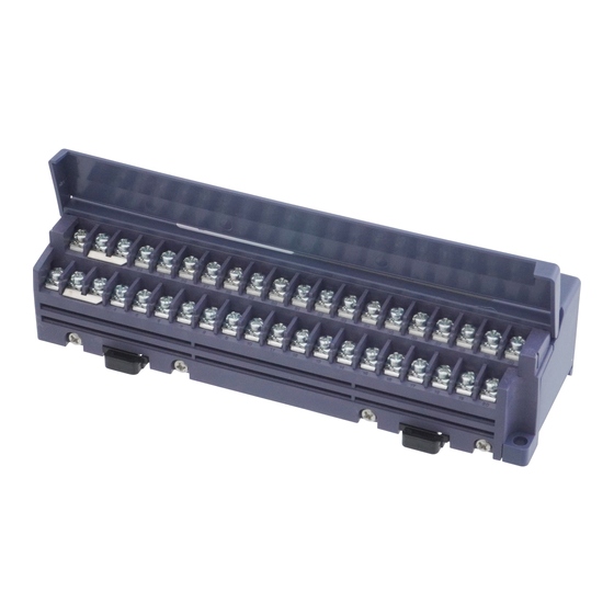
Page 99: Input Terminal
Input indicators (Green) Each indicator will light up when the input signal of the corresponding channel is turned ON. Transmission indicator This indicator will blink when the synchronization signal is sent from the S-LINK V controller. (Green) Transmission cable con- Used for connection of the S-LINK V system transmission cable. - Page 100 Green LED (lights up when there is power between the “24V DC” power supply terminal and “0V”, and between “+” and “-“) Transmission Green LED (blinks when the synchronization signal is sent from the S-LINK V controller) Input Green LED (lights up when the input signal of the corresponding channel is turned ON) Ambient temperature -10 to +55°C (No dew condensation or icing allowed) (Note 3), Storage: -20 to +70°C...
- Page 101 Input Output circuit of input device – – (Shorting piece) S-LINK V system side Internal circuit Input device side Notes: 1) A shorting piece is used for connection of +24V to ‘+’ or 0V to ‘−.’ 2) Remove the shorting piece to use different power supply units for the input device and the input terminal respectively.
- Page 102 Specifications ● Dimensions (Unit: mm) <SL-VTB4> 2- ø4.5 Suitable for 35mm width DIN rail <SL-VTB8> 2-ø4.5 Suitable for 35mm width DIN rail <SL-VTB16, SL-VTB32> 2-ø4.5 Suitable for 35mm width DIN rail Note: SL-VTB32 has a different number of input indicators (green). For a detailed description, refer to page 99.
-
Page 103: Output Terminal
Each indicator will light up when the output signal of the corresponding channel is turned ON. Transmission indicator This indicator will blink when the synchronization signal is sent from the S-LINK V controller. (Green) Used for connection of the S-LINK V system transmission cable. - Page 104 32 points Power Green LED (lights up when there is power between the “24V DC” power supply terminal and “0V”, and between “+” and “-“) Green LED (blinks when the synchronization signal is sent from the S-LINK V controller) Transmission Output...
- Page 105 200mA max. – – (Shorting piece) S-LINK V system side Internal circuit Output device side Notes: 1) A shorting piece is used for connection of +24V to ‘+’ or 0V to ‘–.’ 2) Remove the shorting piece to use different power supply units for the output device and the output terminal respectively.
- Page 106 Specifications ● Dimensions (Unit: mm) <SL-VTBP4> 2- ø4.5 Suitable for 35mm width DIN rail <SL-VTBP8> 2-ø4.5 Suitable for 35mm width DIN rail <SL-VTBP16, SL-VTBP32> 2-ø4.5 Suitable for 35mm width DIN rail Note: SL-VTBP32 has a different number of output indicators (orange). For a detailed description, refer to page 103.
-
Page 107: Connector Input Unit
This indicator will light up when the power is supplied. Input indicators (Green) Each indicator will light up when the input signal of the corresponding channel is turned ON. Transmission indicator This indicator will blink when the synchronization signal is sent from the S-LINK V controller. (Green) - Page 108 Green LED (lights up when the power is supplied) Transmission Green LED (blinks when the synchronization signal is sent from the S-LINK V controller) Input Green LED (lights up when the input signal of the corresponding channel is turned ON) Ambient temperature -10 to +55ºC (No dew condensation or icing allowed), Storage: -20 to +70ºC...
- Page 109 Power supply circuit +24V +24V Input Output circuit of input device N.C. S-LINK V Internal circuit Input device side system side Non-voltage contact, NPN open-collector transistor or DC 2-wire output • Current input: 9mA or less • Operation voltage: ON voltage: 17V or more [between input and +24V] OFF voltage: 4V or less [between input and +24V] •...
- Page 110 Specifications ● Dimensions (Unit: mm) <SL-VT4J> ø2.5 × 4-core flat cable, 0.6m long 14.6 30.5 3 × 7.5 = 22.5 29.5 25.5 18.3 2-ø4.5 Suitable for 35mm width DIN rail <SL-VT4E> ø2.5 × 4-core flat cable, 0.6m long 15.8 3 3 ×...
-
Page 111: Connector Output Unit
This indicator will light up when the power is supplied. Output indicators (Orange) Each indicator will light up when the output signal of the corresponding channel is turned ON. Transmission indicator This indicator will blink when the synchronization signal is sent from the S-LINK V controller. (Green) - Page 112 8 points Power Green LED (lights up when the power is supplied) Green LED (blinks when the synchronization signal is sent from the S-LINK V controller) Transmission Output Orange LED (lights up when the output signal of the corresponding channel is turned ON)
- Page 113 ● Output circuit diagram and terminal layout drawing <SL-VTP□J> Power supply circuit +24V +24V Load Output 200mA max. N.C. S-LINK V system side Internal circuit Output device side Symbols… Z : Surge absorption zener diode : NPN output transistor <SL-VTP□E> Power supply circuit...
- Page 114 Specifications ● Dimensions (Unit: mm) <SL-VTP4J> ø2.5 × 4-core flat cable, 0.6m long 14.6 30.5 3 × 7.5 = 22.5 29.5 25.5 18.3 2-ø4.5 Suitable for 35mm width DIN rail <SL-VTP4E> ø2.5 × 4-core flat cable, 0.6m long 15.8 3 3 ×...
-
Page 115: Mil Connector Input Unit
Not used. (Setting to the OFF status is recommended.) Input indicators (Green) Each indicator will light up when the input signal of the corresponding channel is turned ON. Transmission indicator This indicator will blink when the synchronization signal is sent from the S-LINK V controller. (Green) - Page 116 Number of input points 16 points Transmission indicator Green LED (blinks when the synchronization signal is sent from the S-LINK V controller) Input indicator Green LED (lights up when the input signal of the corresponding channel is turned ON) Ambient temperature -10 to +55ºC (No dew condensation or icing allowed), Storage: -20 to +70ºC...
- Page 117 Input Output circuit +24V +24V of input device mark (on connector side) S-LINK V Internal circuit Input device side system side Non-voltage contact, NPN open-collector transistor or DC 2-wire output • Current input: 5mA or less • Operation voltage: ON voltage: 17V or more [between input and +24V] OFF voltage: 4V or less [between input and +24V] •...
-
Page 118: Mil Connector Output Unit
OFF: Will not hold the current output conditions (output OFF). Output indicators Each indicator will light up when the output signal of the corresponding channel is turned ON. (Orange) Transmission indicator This indicator will blink when the synchronization signal is sent from the S-LINK V controller. (Green) - Page 119 Number of output points 16 points Transmission indicator Green LED (blinks when the synchronization signal is sent from the S-LINK V controller) Output indicator Orange LED (lights up when the output signal of the corresponding channel is turned ON) Output holding function...
- Page 120 (on connector side) Load Output 100mA max. +24V +24V +24V +24V mark (on connector side) S-LINK V Internal circuit Output device side system side Symbols… Z : Surge absorption zener diode : NPN output transistor ● Dimensions (Unit: mm) 67.6 55.7 32.7...
-
Page 121: Analogue Input Unit
AVERAGE (max. of 99 times) and the current data are averaged to carry out A/D conversion. The response time is approx. 50ms (Excluding the delay of S-LINK V response time) Valid / Invalid of the hold function is set. (ON side: valid) HOLD This is used along with PEAK / BOTTOM switch. - Page 122 16 points Power Green LED (lights up when the power is ON) Transmission Green LED (blinks to indicate the synchronization signal transmission from S-LINK V controller) External synchronization Green LED (lights up when external synchronization signal is input) signal input...
- Page 123 4 to 20mA range circuit G (Black) Approx. 30Ω 0V (Blue) COM. Internal circuit Input device side S-LINK V system side <Voltage input> Power supply circuit Color code +24V (Brown) Operational Analogue input amplifier Approx. 900Ω D (White) +1 to +5V range...
- Page 124 Specifications No. Terminal Function Current input terminal Analogue GND Voltage input terminal Analogue GND Not connected Power supply for external synchronization input device +24V (output) Power supply for external synchronization input device 0V External synchronization input terminal ● Analogue input and conversion data ●...
- Page 125 Specifications ● Data bit • Data bit has been allocated as shown in the table below. Data bit Signal IN 0 Conversion data 0 bit (LSB) IN 1 Conversion data 1 bit IN 2 Conversion data 2 bit IN 3 Conversion data 3 bit IN 4 Conversion data 4 bit...
- Page 126 Specifications ● Dimensions (Unit: mm) (59.4) (11.1) 5.25 (3.81) (3.81×7=26.67) (41.07) 27.2 18.3 13 9 2-ø4.5 Suitable for 35mm width DIN rail...
-
Page 127: Analogue Output Unit
Address is set. Output hold setting switch It is used to set the output hold function. Power indicator (Green) Lights up when the power is ON. Transmission indicator Blinks when the synchronization signal is sent from the S-LINK V controller (Green) - Page 128 12 points Power indicator Green LED (lights up when the power is ON) Transmission indicator Green LED (blinks to indicate the synchronization signal transmission from S-LINK V controller) Output holding function Incorporated Ambient tempera- -10 to +55°C (No dew condensation or icing allowed), Storage: -20 to +70°C...
- Page 129 Analogue voltage output -10 to +10V COM. 0V (Blue) S-LINK V system side Internal circuit Output device side When the shield cable is used, connect the shield wire to the frame ground etc. in the analogue input device side. However, take care that there may be cases where it is better not to connect the shield wire depending on the mounting conditions.
- Page 130 Specifications ● Analogue output and conversion data ● 4 to 20mA range ● +1 to +5V range 20.38 5.095 (4000) (4000) Conversion data Conversion data ● 0 to +10V range ● -10 to +10V range 10.48 10.24 (4000) Conversion data (2000) (4000) -10...
- Page 131 Specifications ● Dimensions (Unit: mm) (59.4) (11.1) 5.25 (3.81) (3.81×7=26.67) (41.07) 27.2 18.3 13 9 2-ø4.5 Suitable for 35mm width DIN rail...
-
Page 132: Relay Output Terminal
Power indicator (Green) This indicator will light up when the power is supplied. Transmission indicator This indicator will blink when the synchronization signal is sent from the S-LINK V controller. (Green) Operation indicator Lights up when each output relay is turned ON. - Page 133 Cover: 1 pc., Switch cap: 1 pc., Relay remover key: 1 pc. Notes: 1) This product is incorporated with the PA-N relay manufactured by Panasonic Corporation. However, when you replace the relay, you can also use the PhotoMOS relay manufactured by Panasonic Corporation.
- Page 134 Color code Output relay +24V (Brown) SL-VTPR4: Output 0 to 3 Output SL-VTPR8: Output 0 to 7 D (White) G (Black) 0V (Blue) S-LINK V Internal circuit Output device side system side <SL-VTPR4> <SL-VTPR8> Terminal No. Terminal No. Upper side...
-
Page 135: Input Module
8-channel 16-channel Model No. SL-VM8 SL-VM16 Supply voltage 24V DC±10% (Supplied from S-LINK V controller or separate power supply) Current consumption 18mA or less (Note 1) 20mA or less (Note 1) (24V DC) Address setting 0 to 511 (Set by No.19 to 28) Photo-coupler input: •... - Page 136 • Current input: 6mA or less • Operation voltage: ON voltage: 17V or more [between COM. (+) and IN] OFF voltage: 4V or less [between COM. (+) and IN] S-LINK V Input device side • Input impedance: Approx. 6.5kΩ system side Pin No.
-
Page 137: Output Module
8-channel 16-channel Model No. SL-VMP8 SL-VMP16 Supply voltage 24V DC±10% (Supplied from S-LINK V controller or separate power supply) Current consumption 60mA or less (Note 1) 95mA or less (Note 1) (24V DC) Address setting 0 to 511 (Set by pins No. 19 to 28) NPN open-collector transistor (photo-isolation) •... - Page 138 OUT0 Load 100mA OUT15 max. 24V DC ±10% COM. (-) Symbols… Z : Surge absorption zener diode S-LINK V Output device side : NPN output transistor system side Pin No. Description Pin No. Description Pin No.1 COM. (-) Output common –...
-
Page 139: Picking Switch
Lamp *For a detailed description of two-stage indication mode, refer to page 140. 4 pin type snap male An SL-CP2 is included as a connector to connect the main cable and branch cable of the S-LINK V. connector Lever switch... - Page 140 When the output signal from the signal transmission line is OFF: Lamp turns OFF. Transmission indicator Green LED (blinks to indicate the synchronization signal transmission from S-LINK V controller) Ambient temperature 0 to +55°C (No dew condensation allowed), Storage: -20 to +60°C...
- Page 141 (PLC etc.) Lights up Lamp operation Lights up in green Blinks in blue Turn OFF Lever input operation S-LINK V Lamp signal T (ms) S-LINK V Lamp signal T (ms) Number of I/O points B mode C mode Number of I/O points...
-
Page 142: Picking Switch For Shutter
Lamp *For a detailed description of two-stage indication mode, refer to page 143. 4 pin type snap male An SL-CP2 is included as a connector to connect the main cable and branch cable of the S-LINK V. connector Lever switch Operating the lever switch turns the input ON. - Page 143 When the output signal from the signal transmission line is OFF: Lamp turns OFF. Transmission indicator Green LED (blinks to indicate the synchronization signal transmission from S-LINK V controller) Ambient temperature 0 to +55°C (No dew condensation allowed), Storage: -20 to +60°C...
- Page 144 (PLC etc.) Lights up Lamp operation Lights up in green Blinks in blue Turn OFF Lever input operation S-LINK V Lamp signal T (ms) S-LINK V Lamp signal T (ms) Number of I/O points B mode C mode Number of I/O points...
-
Page 145: Address Setting Remote Controller
Specifications Address setting remote controller ● Part description Designation Function The light emitting and receiving part for infrared communication. Infrared communication part (Position the infrared communication part so that it faces the picking switch SL-VPK0□ at a distance of 100mm or less.) SEND indicator (Red) Blinks at the time of signal transmission. - Page 146 Specifications ● Specifications Designation Address setting remote controller Model No. SL-VAR1 Version Ver.101 Compatible model SL-VPK01, SL-VPK02 Power supply AAA alkaline batteries: 2 pcs Battery life 24 hours continuous use (Ambient temperature: +25°C) Auto sleep Incorporated (3 minutes) Transmission method Infrared (using the Association for Electric Home Appliances format) Emitting element Infrared LED (940nm)
-
Page 147: End Unit
Specifications End unit Each unit of the S-LINK V system needs at least one end unit. ● Part description Designation Function Power indicator (Green) This indicator will light up when the power is supplied. Signal line connection This indicator will light up when the signal waveform is confirmed. - Page 148 Specifications ● Dimensions (Unit: mm) <SL-VEU> ø2.5 × 4-core flat cable, 0.6m long LINE SIDE <MS-CH> 2-ø4.4 Suitable for 35mm width DIN rail 10.2...
-
Page 149: Handy Monitor
Specifications Handy monitor For a detailed description of the handy monitor (SL-VHM1), refer to the ‘Handy Monitor NOTE (SL-VHM1) Instrunction Manual.’ ● Part description... - Page 150 Switches the data input mode to ‘VALID’ or ‘INVALID.’ INVALID selector key Press and hold this switch for 1 second or more to switch the data input mode. Data input switches Inputs data by inputting 16 addresses of signals to the S-LINK V system.
- Page 151 Specifications ● Specifications Designation Handy monitor Model No. SL-VHM1 Supply voltage 24V DC − 5 Current consumption 500mA or less (excluding the connected unit drive power) Allowable passing current 7A or less Number of connectable units 1 unit for 1 system (common to both master mode and slave mode) Master mode and slave mode (Selected by mode selector switch) Operation mode Master mode: Controller function + I/O test function...
- Page 152 If you start wiring work without turning off the power, the S-LINK V controller and the SL-VHM1 may malfunction. 2) To use the SL-VHM1 in the master mode, be sure to disconnect the other S-LINK V controllers from the main line.
-
Page 153: Cable
Specifications Cable Conductor cross Type Model No. Cable length Conductor resistance Allowable passing current section SL-RCM100□ 100m 7A or less Exclusive 4-core flat cable 0.5mm Approx. 0.04Ω/m (At ambient temperature of 25°C) SL-RCM200 200m Hook-up connector CAUTION The SL-J□ connector can be used for the exclusive 4-core flat cable only. To use the other cabtyre cable (commercially available), be sure to use the junction connector com- mercially available. - Page 154 Specifications ● Dimensions (Unit: mm) <SL-J1A> <SL-J3A> 1215 1215 <SL-JK, SL-JK1> <SL-CP1, SL-CP2> 13.5 14.1 18 15 21.8 <SL-CP3> <SL-CJ1, SL-CJ2> 11.2 12.5 13.5 23.5...
-
Page 155: List Of Programmable Logic Controllers (Plc) (Upper Models)
List of programmable logic controllers (PLC) (upper models) This section shows the list of programmable logic controllers (PLC) and their manufacturers in order to clarify the programmable controllers that can control each unit of the S-LINK V system. CAUTION Select PLC I/O connector compatible with your PLC. -
Page 156: List Of Models
The other connectors are the 360-type 40-pin connectors manufactured by Fujitsu Component Ltd. <PLC output connectors> Model No. Applicable manufacturer Applicable PLC Applicable output module FPΣ (excluding FPG-C32T) FPG-XY64D2T (Y side) FP2-Y32T Panasonic Industrial Devices SUNX Co., Ltd. SL-VP1 AFP7Y32T FP3, FP10S, FP10SH AFP33487-F Toshiba Machine Co., Ltd. TC200 TC64DON NS-Y64-T1... -
Page 157: Controller
SL-VPCI PCI bus control the S-LINK V system. This control board is directly connected to the VME bus line to control the S-LINK V S-LINK V control board for SL-VVMES2 system. Since this control board is incorporated with 2 ports (512 points, each) for I/O VME bus machines, use of this control board enables control of up to 1,024 points of I/O devices. -
Page 158: List Of I/O Units
List of Models List of I/O units Designation Model No. Description 1-channel input unit SL-VCH10 Input: 1 point Enables connection of 1 point of the input device. 2-channel input unit SL-VCH20 Input: 2 points Enables connection of 2 points of the input device. Input: 1 point Enables connection of 1 point of the input device and 1 point 2-channel I/O mixed unit... -
Page 159: List Of Connectors
In addition, this monitor is incorporated with the S-LINK V controller functions. For this reason, even in the middle of installation work, this monitor can carry out I/O check for a divided conveyor, or the like, without activating the S-LINK V controller. Address setting remote controller Designation Model No. -
Page 160: Others
Address label SL-VMA1 Affix this label to various S-LINK V units for easy identification of the set addresses. 4 colors (White / Pink / Green / Gray) of address labels for each system are included Address label (4-color set) SL-VMA1-SET as a set. -
Page 161: Chapter 5 Troubleshooting
Chapter 5 Troubleshooting... -
Page 162: Troubleshooting
Troubleshooting This section describes how to solve the problems. If your S-LINK V system does not operate properly, refer to this section. Flowchart for taking corrective action for detected error You can check the detected error using the LED indicators or the address display of the controller. - Page 163 Troubleshooting <For S-LINK V control board> Occurrence of error Check the transmissoin Check that the power is supplied. and error indicators of Also check the +24V to 0V line for the control board. short-circuit. One of them is on or blinking.
- Page 164 Troubleshooting Check the system configuration. Abnormal Check the end unit. Correctly connect the end unit. Normal Refer to page 18. After starting the sys- tem, system setting is carried out. Carry out system setting. Refer to page 66 and following pages.
-
Page 165: Flowchart For Power Supply Condition Check
Troubleshooting Flowchart for power supply condition check Check the power supply conditions. Problem Check the terminal detected screws for looseness. Check the Tighten the terminal screws, or power supply line for disconnec- replace the power supply line. tion and short-circuit. No problem detected Problem detected... - Page 166 Notes: 1) If the control board is used, check the error number shown by the in-board memory. 2) If an error occur, the transmission of S-LINK V system will automatically recover when the cause is removed. However, the error record remains. For release, refer to page 168.
-
Page 167: How To Identify Error Unit After Error Detection
In this mode, you can identify the address of the problem unit. : PLC I/O unit (The white number is the connector number.) : S-LINK V I/O unit (The number shows the address of the unit.) <Example 1> <Example 2>... -
Page 168: How To Extinguish Error Indicator
Troubleshooting How to extinguish error indicator WARNING Before canceling the error, be sure to confirm the details of the error, and then turn off the power. After power-off, be sure to eliminate the cause of the error, and then turn on the power again. If the power is not turned off, a serious problem may occur. -
Page 169: Appendix
Appendix... -
Page 170: Appendix
Appendix List of error numbers If the S-LINK V system causes an error, the error indicator, address display, and error output will inform the er- ror. Check the details of the error, and take optimum measures. Error No. Cause of error... -
Page 171: Flowchart For Error Detection
Appendix Flowchart for error detection Occurrence of error Output of error output terminal: OFF If error output is set (Low → Hi) The error indicator will light up. The error number will appear on the address display. Error number 1. Error 1 or 2 2. -
Page 172: Selection Of Connector Link Cable
70 : SL-VF70 (70mm) 150 : SL-VF150 (150mm) 250 : SL-VF250 (250mm) ● Modules using SL-VS1 and SL-VP1 FPG-XY64D2T FP2-X32D2, FP2-Y32T AFP33027-F, AFP33487-F (Panasonic Industrial Devices SUNX) (Panasonic Industrial Devices SUNX) (Panasonic Industrial Devices SUNX) Panasonic Panasonic Panasonic FP3/FP10S/ FPΣ... - Page 173 Appendix ● Module using SL-VS3 and SL-VP3 A1SX41, A1SX41-S1, A1SX42, A1SX42-S1, A1SH42 AX42, AH42, AJ35TC1-32D, AY42, AJ35TC1-32T (Mitsubishi Electric) A1SH42-S1, A1SY41, A1SY42 (Mitsubishi Electric) Mitsubishi Mitsubishi AnN/AnA/AnU AnS series QnA/QnAs/A2CJ 150 150 NP1X3206-W, NP1X6406-W, NP1Y32T09P1, NP1Y64T09P1 QX41, QX42, QH42P, QY41P, QY42P (Mitsubishi Electric) (Fuji Electric FA Components &...
- Page 174 Appendix ● Modules using SL-VS5 and SL-VP5 CJ1W-ID231, CJ1W-ID261, CJ1W-MD261, CJ1W-OD231, CJ1W-OD261 C500-ID219, C500-OD213 (OMRON) CS1W-ID231, CS1W-ID261, CS1W-MD261, CS1W-OD231, CS1W-OD261 C200H-ID216, C200H-ID217, C200H-OD218, C200H-OD219 (OMRON) OMRON CJ1 series/CS1 series OMRON CVM1/CV /C200H series /C1000H/C2000H /C500 CQM1-ID213, CQM1-OD213 (OMRON) XD64-6N, WD64-6N, YD64-1A (Yokogawa Electric) <OMRON CQM1>...
- Page 175 Appendix ● Modules using SL-VS6 and SL-VP6 XDC24D2H, XDC24D3H, YTR24DH, YTR24D3H (Hitachi Industrial Equipment Systems) <Hitachi H series> 150 150 ● Modules using SL-VS7 and SL-VP5 B2605 (YASUKAWA Electric) <YASUKAWA GL20/GL40S/GL60S/GL60H/GL70H> 150 150 ● Modules using SL-VS8 and SL-VP8 1746-IV32, 1746-OV32 [Rockwell Automation Japan (Allen-Bradley)] <Allen-Bradley SLC500>...
-
Page 176: Setting Of Connector Numbers,Addresses
Appendix Setting of connector numbers, addresses, and number of I/O control points To set the PLC I/O connector numbers, I/O unit addresses, and number of I/O control points, refer to pages 33, 72 and following pages. SL-VS□ SL-VP□ SL-VCU1 SL-VS□ SL-VP□... -
Page 177: Glossary
Number showing the address Address For the S-LINK V system, this number should be set for each I/O unit. Contraction of 'binary digit.' Binary numbers will be set for bits. In other words, '0' or '1' will be set for each bit. - Page 178 Total cable length This length depends on the transmission mode. This cable is used for connection of I/O units that are controlled by the S-LINK V protocol. This cable Transmission cable consists of 4 wires: +24V and 0V power supply line wires and D and G signal transmission line wires.
-
Page 179: Fax Sheet For Asking Question
FAX Sheet for Asking Question If you have a question about the S-LINK V system (regarding designing, installation, etc.), copy this page, and then write your question in details. After that, fax the written sheet. We will answer your question. - Page 180 MEMO...
- Page 181 3. DISCLAIMERS (1) Panasonic Industrial Devices SUNX's sole obligation and liability under this warranty is limited to the repair or re- placement, or refund of the purchase price, of a defective Product, at Panasonic Industrial Devices SUNX's option.
- Page 182 ■ Overseas Sales Division (Head Office): 2431-1 Ushiyama-cho, Kasugai-shi, Aichi, 486-0901, Japan ■ Telephone: +81-568-33-7861 ■ Facsimile: +81-568-33-8591 panasonic.net/id/pidsx/global For sales network, please visit our website. © Panasonic Industrial Devices SUNX Co., Ltd. 2018 October, 2018 PRINTED IN JAPAN WUME-SLINKV-8...
Need help?
Do you have a question about the S-LINK V and is the answer not in the manual?
Questions and answers