Sign In
Upload
Manuals
Brands
Panasonic Manuals
Control Unit
S-LINK V
Panasonic S-LINK V Manuals
Manuals and User Guides for Panasonic S-LINK V. We have
2
Panasonic S-LINK V manuals available for free PDF download: User Manual, Instruction Manual
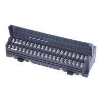
Panasonic S-LINK V User Manual (182 pages)
Flexible Wire-Saving System
Brand:
Panasonic
| Category:
Controller
| Size: 6.18 MB
Table of Contents
Table of Contents
3
Before Using this System
5
Introduction
6
Warnings
6
Instructions for Safe Use
7
Ambient Conditions
7
Instructions for Designing
8
Instructions for Use
8
Fail-Safe Function
8
Conformity to EC Directives
8
Use with S-LINK System
8
Instructions for Installation
9
Instructions for Disposal
9
Hook-Up Cable Connectors
9
Wiring
9
Others
9
Designing / Installation Procedures
10
Chapter 1 Designing System
13
System Configuration
14
Outline of Design
16
Selection of Controller or Control Board
16
I/O Control Points
16
Transmission Distance
16
Outputting Error Signals
17
Connection of End Unit
18
Link Cable
18
Control Cable Selection Method
18
VCU1 Only)
18
Connector Link Cable Selection Method
18
(For Use of SL-VCU1 Only)
18
Connectors
19
Calculation of Total Current Consumption Value ·20
20
Power Supply Capacity of System
20
Consumption
22
Calculation of Voltage Drop Value
23
Rated Voltage
23
Necessity of Local Power Supply Unit
24
Designing of System Using Local Power
24
Supply Method
24
Input Unit
26
Example: Connection of DC 2-Wire Sensor
27
Transmission Delay Time
28
Response Delay Time
28
Operation at Power
30
Error Signal Outputting Delay Time
30
System Setting Time
31
Output Unit
32
Output Holding Function Setting Method
32
Address Setting
33
Setting of PLC I/O Connector Numbers
33
Setting of I/O Unit Addresses
33
Example: Address Setting
34
Chapter 2 Wiring
35
Flowchart
36
Basic Procedures
37
Connector Hook-Up Work
37
Cutting of Exclusive 4-Core Flat Cable
37
How to Use Exclusive Hook-Up Pliers (SL-JPS, SL-JPC, SL-JPE)
38
Hook-Up of Connector
39
Hook-Up Method of SL-JK Connector
39
For 'T'- Branch
39
Hook-Up Method of SL-J1A Connector for 'T' - Branch and SL-J3A Connector for Cable Extension
41
CJ1 and SL-CJ2 Snap Female Connectors
44
Connection to Terminal Block
46
Extension of Main / Branch Line Cable
47
Extension of Exclusive 4-Core Flat Cables ·47
47
Extension of Cable Excluding Exclusive 4-Core Flat Cables
47
Extension of Cable to I/O Device
47
Installation
48
Installation of each Unit
48
Power Supply
50
Construction
50
Power Supply to System
50
Connection of each Unit
51
Connection of Controller
51
Connection of Bus Direct-Connection Type Controller and Control Board
52
Connection of PLC I/O Connector
53
Connection of I/O Unit
55
Connection of I/O Device
56
Connection of Main Line Cable to End Unit ·57
57
Connection of Local Power Supply Unit
58
Local Power Supply to System
58
Installation Method of Batteries
59
Chapter 3 Starting System
61
Flowchart
62
Check before Starting
64
Wiring Check
64
Check of Wiring Conditions of Controller and Control Board
64
Check of PLC I/O Connectors
65
Check of Cable for Short-Circuit
65
Power-On (Main Power and Local Power)
66
Starting
66
CONFIG Mode
66
Check of Recognized Addresses
70
CHECK Mode
70
Chapter 4 Specifications
71
Specifications
71
Common Specifications
72
Address Setting Switches
72
Specifications of each Unit
75
Controller
75
Bus Direct-Connection Type Controller for FP2 / FP2SH Series
79
Mitsubishi MELSEC-Q Series PLC Bus Direct-Connection Type Controller
83
Control Board
87
Control Module
91
PLC I/O Connector
93
I/O Unit
96
Input Terminal
99
Output Terminal
103
Connector Input Unit
107
Connector Output Unit
111
MIL Connector Input Unit
115
MIL Connector Output Unit
118
Analogue Input Unit
121
Analogue Output Unit
127
Relay Output Terminal
132
Input Module
135
Output Module
137
Picking Switch
139
Picking Switch for Shutter
142
Address Setting Remote Controller
145
End Unit
147
Handy Monitor
149
Cable
153
Hook-Up Connector
153
List of Programmable Logic Controllers (PLC) (Upper Models)
155
List of Models
156
Controller
157
Control Board
157
Control Module
157
List of I/O Units
158
List of Connectors
159
Handy Monitor
159
Address Setting Remote Controller
159
Others
160
Chapter 5 Troubleshooting
161
Troubleshooting
162
Detected Error
162
Flowchart for Power Supply Condition Check
165
How to Identify Error Unit after Error Detection
167
How to Extinguish Error Indicator
168
Utilization of Output Holding Function
168
Appendix
169
Appendix
170
List of Error Numbers
170
Flowchart for Error Detection
171
Selection of Connector Link Cable
172
Setting of Connector Numbers,Addresses
176
And Number of I/O Control Points
176
Glossary
177
FAX Sheet for Asking Question
179
Advertisement
Panasonic S-LINK V Instruction Manual (16 pages)
Flexible Wire-saving Link
Brand:
Panasonic
| Category:
Control Unit
| Size: 0.41 MB
Advertisement
Related Products
Panasonic SL-VPCI
Panasonic SL-PC104
Panasonic SF-C21
Panasonic SF-C13
Panasonic Photovoltaic Module HIT VBHN SJ25 Series
Panasonic Photovoltaic Module HIT VBHN SJ47 Series
Panasonic SF4D-TM1
Panasonic SF-C10 Series
Panasonic SF-C14EX-10
Panasonic SF-C12
Panasonic Categories
Camcorder
Air Conditioner
TV
Digital Camera
Cordless Telephone
More Panasonic Manuals
Login
Sign In
OR
Sign in with Facebook
Sign in with Google
Upload manual
Upload from disk
Upload from URL