Table of Contents
Advertisement
Quick Links
™
Instruction manual
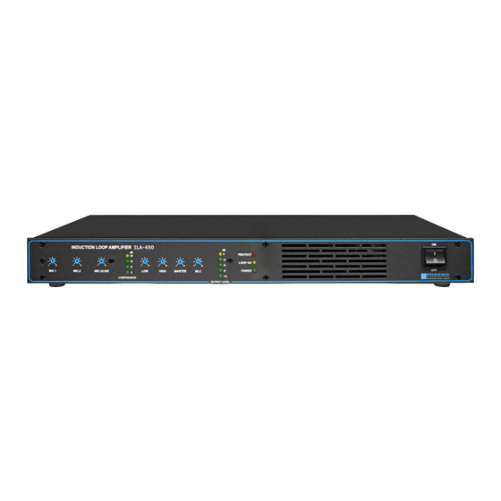
ILA-450
INDUCTION LOOP AMPLIFIER
Now with „MLC" correction for frequency errors, COMPRESSOR, loop impedance monitoring
and SPEAKON output jack.
Phoenix Professional Audio GmbH
Gewerbepark Markfeld 5
D-83043 Bad Aibling / Germany
Tel.: +49(0)8061-495603-0
Fax: +49(0)8061-495603-1
www.phoenix-pa.com
www.phoenix-pa.com/shop
© Copyright 2018 Phoenix Professional Audio GmbH
www.phoenix-pa.com / www.phoenix-pa.com /shop
Phoenix logo is registered with the DE Patent and Trademark Office (TM)
All trademarks are the property of their respective owners
M a d e i n E U
For Systems
according to
EN 60118-4
IEC 118-4
DOC-050718
Advertisement
Table of Contents

Related Manuals for Phoenix ILA-450


Summary of Contents for Phoenix ILA-450
- Page 1 D-83043 Bad Aibling / Germany Tel.: +49(0)8061-495603-0 Fax: +49(0)8061-495603-1 www.phoenix-pa.com www.phoenix-pa.com/shop © Copyright 2018 Phoenix Professional Audio GmbH www.phoenix-pa.com / www.phoenix-pa.com /shop Phoenix logo is registered with the DE Patent and Trademark Office (TM) All trademarks are the property of their respective owners DOC-050718...
- Page 2 COVER. USE QUALIFIED PERSONNEL FOR ALL MAINTENANCE WORK. © Copyright 2018, Phoenix Professional Audio GmbH, www.phoenix-pa.com Phoenix logo is registered with the DE Patent and Trademark Office (TM) All trademarks are the property of their respective owners - 1 -...
-
Page 3: General Information
™ Instruction manual GENERAL INFORMATION The ILA-450 Induction Loop Amplifier for audio transmission is widely used to provide hearing aids with inductive audio signals. The ILA-450 Phoenix Induction Loop Amplifier was developed as a high-quality LOOP amplifier for medium induction loops. - Page 4 The magnetic field outside the intended range loses strength rather quickly and drops to zero. This is done by coupling a phase shifter FS-1, which is connected between the two ILA-450, which in turn generates a signal phase difference of 90 degrees in the electrical flow through two adjacent induction loops.
-
Page 5: Safety Instructions
™ Instruction manual SAFETY INSTRUCTIONS Before putting the induction loop amplifier ILA-450 into operation, we ask you to carefully read the safety instructions. We ask you to perform the installation according to the following guidelines: In a highly visible position, an INDUCTIVE COUPLING sign should be located near the entrance to the area where an induction loop is installed. - Page 6 Rotate the MLC control to get the best playback / transmission of the audio signal on the induction loop while monitoring the audio signal via the headset with the ILA-E receiver. Repeat the measurement procedure for all ILA-450 induction loop amplifiers or induction loops bound in the system.
- Page 7 The loop impedance measurement only takes place when the input signal is inserted. After removing the fault, always „reset“ the loop amplifier ILA-450 by switching off the amplifier with the POWER button, wait 3 seconds and then turn it on again with the POWER button.
-
Page 8: Rear Side / Connections
REAR SIDE / CONNECTIONS 1.- POWER INPUT 230VAC/50-60 Hz 230VAC power input. For connecting the ILA-450 to the mains using the power cord. 2.- LOOP CABLE SPEAKON socket 2-pin, the loop cable should be connected to the terminals (+ pin) and (- pin). - Page 9 1 GND und wire bridge to 3 2 +IN 2 +IN 3 -IN © Copyright 2018, Phoenix Professional Audio GmbH, www.phoenix-pa.com Phoenix logo is registered with the DE Patent and Trademark Office (TM) All trademarks are the property of their respective owners - 8 -...
-
Page 10: Technical Appendix
4.0 mm 115 meters 190 meters CONSTRUCTION SIMPLE LOOP SYSTEM A simple induction loop system consists of a LOOP amplifier ILA-450 and one or more equal size induction loops, see drawing. Figure 1.1 shows single loop Figure 1.2 shows double loop ©... - Page 11 Rooms and areas where an induction loop has been installed should be marked accordingly. Please lead parallel lines close together. © Copyright 2018, Phoenix Professional Audio GmbH, www.phoenix-pa.com Phoenix logo is registered with the DE Patent and Trademark Office (TM) All trademarks are the property of their respective owners - 10 -...
- Page 12 Rooms and areas where an induction loop has been installed should be marked accordingly. © Copyright 2018, Phoenix Professional Audio GmbH, www.phoenix-pa.com Phoenix logo is registered with the DE Patent and Trademark Office (TM) All trademarks are the property of their respective owners...
- Page 13 This in turn supplies the first loop in the system. Due to the phase modulation, the audio signal is shifted by 90˚ phases and forwarded to the second ILA-450. The second ILA-450 then has to supply the second parallel induction loop throughout the system. All LOOP segments should be equal and should not exceed ranges of 2 to 5 meters.
- Page 14 LOOP SYSTEM WITH 90 DEGREES PHASE SHIFT according to EN 60118-4 Example of a simple LOOP SEGMENT induction loop system with two ILA-450 (MASTER / SLAVE) and FS-1 90 degree phase shifters. It is important that the induction loops are approximately the same size.
- Page 15 Rooms and areas where an induction loop has been installed should be marked accordingly. © Copyright 2018, Phoenix Professional Audio GmbH, www.phoenix-pa.com Phoenix logo is registered with the DE Patent and Trademark Office (TM) All trademarks are the property of their respective owners...
- Page 16 Phased Array System Due to the phase modulation, the audio signal is shifted by 90˚ phases and forwarded to the second ILA-450 or to the second induction loop. The second ILA-450 then has to supply the second parallel induction loop in the entire inductive hearing aid system.
- Page 17 SIGNAL INPUT MASTER 0 FS-1 network side SLAVE 90 © Copyright 2018, Phoenix Professional Audio GmbH, www.phoenix-pa.com Phoenix logo is registered with the DE Patent and Trademark Office (TM) All trademarks are the property of their respective owners - 16 -...
- Page 18 11.4 12.2 13.0 13.8 14.6 15.4 16.2 17.0 © Copyright 2018, Phoenix Professional Audio GmbH, www.phoenix-pa.com Phoenix logo is registered with the DE Patent and Trademark Office (TM) All trademarks are the property of their respective owners - 17 -...
- Page 19 11.4 12.2 13.0 13.8 14.6 15.4 16.2 17.0 © Copyright 2018, Phoenix Professional Audio GmbH, www.phoenix-pa.com Phoenix logo is registered with the DE Patent and Trademark Office (TM) All trademarks are the property of their respective owners - 18 -...
- Page 20 Induction loop no. 1 (the first ILA-450) Induction loop no. 2 (the second ILA-450) Induction loop „total“ (the first ILA-450 and the second ILA-450 induction loop amplifiers in the system) © Copyright 2018, Phoenix Professional Audio GmbH, www.phoenix-pa.com Phoenix logo is registered with the DE Patent and Trademark Office (TM)
- Page 21 © Copyright 2018, Phoenix Professional Audio GmbH, www.phoenix-pa.com Phoenix logo is registered with the DE Patent and Trademark Office (TM) All trademarks are the property of their respective owners - 20 -...
-
Page 22: Technical Data
Technical changes and printing errors reserved. The pictures are similar, color deviations reserved. © Copyright 2018, Phoenix Professional Audio GmbH, www.phoenix-pa.com Phoenix logo is registered with the DE Patent and Trademark Office (TM) All trademarks are the property of their respective owners - 21 -...
Need help?
Do you have a question about the ILA-450 and is the answer not in the manual?
Questions and answers