Table of Contents
Advertisement
Quick Links
Artikelnummer/Article no.
Operating instructions
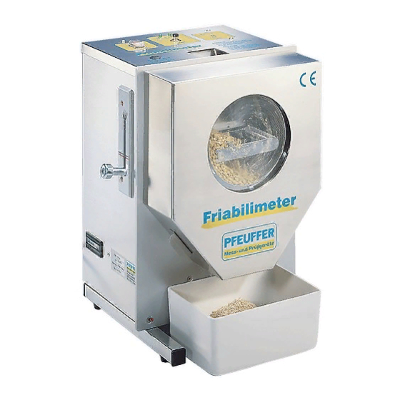
Malt friability measuring instrument
Friabilimeter
Pfeuffer GmbH
Flugplatzstraße 70
97318 Kitzingen
GERMANY
Phone:
+49 9321 9369-0
Fax:
+49 9321 9369-50
Email:
info@pfeuffer.com
Internet: http://www.pfeuffer.com
1810 0091
Translation of the
original operating instructions
Revision 7/14.09.2016
Advertisement
Table of Contents

Subscribe to Our Youtube Channel
Related Manuals for Pfeuffer Friabilimeter


Summary of Contents for Pfeuffer Friabilimeter
- Page 1 1810 0091 Artikelnummer/Article no. Operating instructions Malt friability measuring instrument Friabilimeter Pfeuffer GmbH Flugplatzstraße 70 97318 Kitzingen GERMANY Phone: +49 9321 9369-0 Fax: +49 9321 9369-50 Email: info@pfeuffer.com Revision 7/14.09.2016 Internet: http://www.pfeuffer.com Translation of the original operating instructions...
- Page 2 Betriebsanleitung Friabilimeter These Operating Instructions are a constituent part of the FRIABILIMETER and must be available to all operating personnel at all times. They are intended for the operating company of the system, the operating personnel and the specialists who are responsible for the transport, assembly, installation, operation, maintenance, cleaning, disassembly and disposal.
-
Page 3: Table Of Contents
Mains disconnector in a portable device ...............9 2.1.2 Protective covers ......................10 Operating and danger areas on the FRIABILIMETER ..............11 Operating and maintenance personnel ................... 12 Safety measures (to be carried out by the owner) ..............12 General safety notes ........................ 13 Safety tests .......................... - Page 4 7.7.2 Whole hyaline (whole grains) WH ................25 7.7.3 Part hyaline (partially non-comminuted grains) PH ............ 26 Switching off the FRIABILIMETER ..................... 26 Checking the device settings ..................... 27 Timer runtime ........................... 27 Abrasion on the pressure roll ....................27 Abrasion on the drive rolls .......................
-
Page 5: Introduction
Introduction Designated use The FRIABILIMETER is used for determining the friability and whole hyaline of barley malt grains directly after kilning. It mechanically separates a malt sample into hard (glassy) and friable (easily crushed) constituents. The FRIABILIMETER consists of a mechanical abrading device with an electric motor and an electronic timer. -
Page 6: Ec/Eu Declaration Of Conformity
Electrical equipment for measurements, control and laboratory use – DIN EN 61326-1:2013 EMC requirements – Part 1: General requirements Any modification to the FRIABILIMETER not agreed with us shall result in this declaration becoming null and void. Kitzingen, __________________________ ___________________________________... -
Page 7: Structural Features Of The Danger Notes
Friabilimeter operating instructions Structural features of the danger notes The operating instructions from Pfeuffer GmbH contain instructions that you must comply with for your personal safety as well as to avoid damage to property. The instructions for your personal safety are highlighted by a warning triangle. -
Page 8: Abbreviations In Electrical Engineering
The type plate with the type designation can be found on the side of the machine housing (rear right). It is important for all questions to specify the correct type designation, serial number and year of manufacture. Only in this way will rapid processing be possible. Sample Pfeuffer GmbH type plate: Pfeuffer GmbH Tel. +49 9321 969-0 Flugplatzstraße 70... -
Page 9: Safety
Main switch ON/OFF The connection for the mains cable (C19/C20 coupler) is located at the rear. In an emergency, switch off the FRIABILIMETER using the main switch, position OFF. Disconnect the mains cable from the electrical power supply, or pull out the coupler. -
Page 10: Protective Covers
Arrange the plug/socket combination at the place of installation so that it can be observed clearly and reached quickly in an emergency. 2.1.2 Protective covers The FRIABILIMETER is protected during operation by its complete housing and the front hood to prevent reaching into the machine. CAUTION Danger of crushing! Finger injuries! ... -
Page 11: Operating And Danger Areas On The Friabilimeter
(e.g. table) is required for this. Danger area The entire area one meter around the FRIABILIMETER is a danger area during maintenance and repair work. Keep the area around the FRIABILIMETER clear of objects. © 2016 – Pfeuffer GmbH... -
Page 12: Operating And Maintenance Personnel
1. The FRIABILIMETER is only allowed to be operated by authorized and instructed people. 2. The responsibilities for operating the FRIABILIMETER must be clearly defined and complied with so that no unclear competencies arise with regard to the aspect of safety. -
Page 13: General Safety Notes
Hazardous substances (in Germany, the technical rules for hazardous substances – TRGS 555 apply) Environmental protection regulations. Electrical connections The FRIABILIMETER is only allowed to be connected to a socket earthed in accordance with the regulations, using a protective conductor. Illuminance The owner must ensure that there is adequate and homogeneous illumination in all areas. -
Page 14: Safety Tests
It is essential to comply with the following switch-off procedure prior to cleaning, maintenance or repair work (only by specialist personnel): Empty the FRIABILIMETER. Switch off the FRIABILIMETER at the main switch position OFF. Disconnect the mains cable from the electrical power supply, or pull out the coupler. -
Page 15: Technical Data
-10 °C – 60 °C storage and transport Ambient temperature 15 °C – 40 °C measurement Atmospheric humidity 20 – 80 % non-condensing Installation condition Level table surface without vibration © 2016 – Pfeuffer GmbH Revision 7 Page 15 of 48... -
Page 16: Delivery, Transport And Storage
The relevant article numbers can be found in chapter 11. Transport and packaging Systems, machines and devices from Pfeuffer GmbH are carefully tested and packaged prior to dispatch, however it is not possible to exclude the risk of damage during transport. -
Page 17: Transport To The Installation Site (By The Customer)
Remove the cardboard box. Figure 5: Unpacking II Open the cardboard box inside. Figure 6: Unpacking III Remove the PE foam padding. Figure 7: Unpacking IV © 2016 – Pfeuffer GmbH Revision 7 Page 17 of 48... -
Page 18: Installation And Commissioning
Note that the weight is approx. 12 kg. Figure 8: Unpacking V Move the FRIABILIMETER to the installation location, paying attention to the setup instructions in chapter 5.1. Keep the original packaging. Packaging for return delivery ... -
Page 19: Function
Operating hours counter Sequence of functions The FRIABILIMETER is a friability measuring instrument for barley malt. The friability is measured using a mechanical abrasion process. Weigh out a cleaned sample of 50 g on a balance with 0.01 g accuracy, and fill the sample. Pull the pull handle and engage it in the bottom position. -
Page 20: Operation
Figure 10: FRIABILIMETER control elements 7.1.1 Main switch ON/OFF The main switch ON/OFF switches the FRIABILIMETER on and off. After switching on, the "On" LED lights 7.1.2 Pull handle The pull handle applies pressure to the pressure roll, or removes the pressure. -
Page 21: Sample Preparation Measures
Fill and seal the container immediately after taking out the sample. It is necessary to calibrate the FRIABILIMETER in relation to a standard malt with a known friability. If the friability result differs from the accepted value by more than... -
Page 22: Weighing Out The Sample
Fill the sample. Figure 12: Filling the sample NOTE The FRIABILIMETER has a safety circuit. The devices switches off immediately when the front hood is removed! The investigation result will be falsified if the correct running time (8 minutes) is not respected. - Page 23 Friabilimeter operating instructions Press the start key. The "On" LED goes out and the "Operation" LED flashes. The FRIABILIMETER switches off automatically after eight minutes. Figure 14: Pressing the start key CAUTION Danger of crushing! Finger injuries! During operation, do not place your fingers into the filling funnel.
-
Page 24: Emptying The Sample
The sieve drum can be damaged if it rolls off the work surface. Always put down the sieve drum flat. Figure 19: Putting the sieve drum down flat Page 24 of 48 Revision 7 © 2016 – Pfeuffer GmbH... -
Page 25: Evaluation
WH = 2 x 0.76 g WH = 1.5 % WH = Whole hyaline in percent (%) - stated to one decimal place = Mass of the manually separated out whole grains in grams. © 2016 – Pfeuffer GmbH Revision 7 Page 25 of 48... -
Page 26: Part Hyaline (Partially Non-Comminuted Grains) Ph
Switching off the FRIABILIMETER Switch off the device at the main switch position OFF. Clean the FRIABILIMETER and the sieve drum after each investigation, see chapter 9. Reinsert the sieve drum and put on the front hood. -
Page 27: Checking The Device Settings
Checking the device settings The Checking the device settings chapter is only intended for specialists. To ensure an accurate investigation, it is essential for the device settings of the FRIABILIMETER to be checked at regular intervals. The FRIABILIMETER is equipped with an operating hours counter as standard. Older devices can be retrofitted by Pfeuffer GmbH. -
Page 28: Abrasion On The Drive Rolls
If the diameter is less than Ø 39.0 mm, have the drive roll renewed by a specialist or by Pfeuffer GmbH's customer service (see chapter 9.5 and 9.5.1). Make a note of the renewal, the calibration and the subsequent check with test malt in a test log (see master copy on last page). -
Page 29: Precise Adjustment Using The Setscrew
Disconnect the mains cable from the electrical power supply, or pull out the coupler. There is a plastic cap on the top of the FRIABILIMETER. Under this plastic cap, there is a setscrew inside the housing. This setscrew directly acts on the spring travel and thus on the force exerted on the sieve drum by the pressure roll. -
Page 30: Adjustment By Moving The Detent Plate
Then tighten the two countersinking screws firmly again. Make a note of the movement of the detent plate and the subsequent check with test malt in a test log (see master copy on last page). Page 30 of 48 Revision 7 © 2016 – Pfeuffer GmbH... -
Page 31: Maintenance And Cleaning
The Maintenance and cleaning chapter is only intended for specialist operators. NOTE Opening the housing and inappropriate operation will invalidate the warranty. To ensure trouble-free operation, it is essential for the FRIABILIMETER to be cleaned and maintained at regular intervals. DANGER... -
Page 32: Cleaning
1-2 mm flat-blade screwdriver for sliding pins • 10 mm hexagon wrench for sliding pins • 2 mm Allen key for chain sprockets and 4 mm Allen key for pull handle Page 32 of 48 Revision 7 © 2016 – Pfeuffer GmbH... -
Page 33: Renewing The Pressure Roll
8.5 and 8.6. Make a note of the renewal, the calibration and the subsequent check with test malt in a test log (see master copy on last page). © 2016 – Pfeuffer GmbH Revision 7 Page 33 of 48... -
Page 34: Working Inside The Housing
Pfeuffer GmbH expressly points out that fitting spare parts and renewing wearing parts are procedures which require a certain level of experience! This work should only be carried out by a specialist if it is not possible to send the FRIABILIMETER to Pfeuffer GmbH' customer service. -
Page 35: Renewing Drive Rolls
Motor plug Pull handle (bottom engagement Drive roll, left position) Serrated washer Drive roll, right Countersinking screw M4 x 16 mm Pressure roll Countersinking screw M4 x 12 mm © 2016 – Pfeuffer GmbH Revision 7 Page 35 of 48... - Page 36 Figure 33: Disconnecting the motor plug Unscrew the two upper chain sprockets using the Allen screws, with an Allen key (2 mm). Figure 35: Unscrewing the chain sprocket Page 36 of 48 Revision 7 © 2016 – Pfeuffer GmbH...
- Page 37 Keep a gap (A) of about 0.2 mm between the chain sprocket and bearing tube. Check this gap with a feeler gage. Grease Figure 39: Drawing showing change of drive roll © 2016 – Pfeuffer GmbH Revision 7 Page 37 of 48...
-
Page 38: Renewing The Timer
Unscrew the pull handle using an Allen key (4 mm). Unscrew the four outer countersinking screws (M4) with a Phillips screwdriver. Pay attention to the installation position of the two upper serrated washers. Page 38 of 48 Revision 7 © 2016 – Pfeuffer GmbH... - Page 39 Unscrew the four fillister head screws for the timer. Pull the timer carefully downwards and out a little. Remove the cover. The circuit board is in the cover. © 2016 – Pfeuffer GmbH Revision 7 Page 39 of 48...
- Page 40 Attach the front plate using the four outer countersinking screws. Pay attention to the installation position of the two upper serrated washers, see Figure 31. Screw the pull handle in firmly. Insert the sieve drum and put on the front hood. Page 40 of 48 Revision 7 © 2016 – Pfeuffer GmbH...
-
Page 41: Renewing The Motor
Chain sprocket Motor pin Figure 44: Motor, complete Table for abbreviations in electrical engineering, see chapter 1.5. Remove the chain from the chain sprocket and take off the motor. © 2016 – Pfeuffer GmbH Revision 7 Page 41 of 48... -
Page 42: Checks
If all functions are correct, the machine can be handed over to the owner. NOTE Following cleaning, maintenance or exchanging wearing parts, check that all safety devices are functioning correctly. Page 42 of 48 Revision 7 © 2016 – Pfeuffer GmbH... -
Page 43: 10 Malfunctions - Causes And Rectification
Appropriate tools and test instruments must be provided to these personnel. If the specified measures do not prove successful, contact Pfeuffer GmbH. It is important for all questions to specify the correct type designation, serial number and year of manufacture. - Page 44 Renew worn parts, see chapters 9.4 and 9.5.1. The timer runtime is incorrect. Check the runtime with a stopwatch. Checking and renewal by Pfeuffer GmbH or by a specialist, see chapter 9.5.2. The friability result The contact pressure of the...
-
Page 45: Renewing The Internal Fuse
(315 mA, slow-blow, 5 x 20 mm) is incorporated in this. NOTE Always refer to the type plate for the precise fuse rating! Switch off the FRIABILIMETER using the main switch and disconnect the mains plug from the electrical power supply. -
Page 46: 11 Spare Parts And Accessories
We wish to point out expressly that replacement and accessory parts not supplied by us will not have been tested and approved by us either. Installing and/or using such products can thus result in the design properties of the FRIABILIMETER being negatively impaired. Pfeuffer GmbH cannot be held liable for damage attributable to the use of non-genuine parts and non-genuine accessories. -
Page 47: 12 Emergency
Friabilimeter operating instructions 12 Emergency In an emergency, disconnect the FRIABILIMETER from the electrical power supply. 13 Dismantling and disposal Dismantling is only allowed to be carried out by specialist personnel, refer to the definition in chapter 2.4. Disconnect the mains plug before you start dismantling. -
Page 48: Test Log
Master copy Test log This log is intended to allow the owner-operator to document the test status of the FRIABILIMETER. Company, location ___________________________________ Company stamp: Year of manufacture _________________________________ Serial number ______________________________________ Operating hours _____________________________________ Check Before each check, first carry out an investigation and dispose of this sample afterwards without logging the values.
Need help?
Do you have a question about the Friabilimeter and is the answer not in the manual?
Questions and answers